EP1662687A2 - Verfahren und Vorrichtung zur Kanalverschachtelung in einem Mobilfunksystem - Google Patents
Verfahren und Vorrichtung zur Kanalverschachtelung in einem Mobilfunksystem Download PDFInfo
- Publication number
- EP1662687A2 EP1662687A2 EP20050026153 EP05026153A EP1662687A2 EP 1662687 A2 EP1662687 A2 EP 1662687A2 EP 20050026153 EP20050026153 EP 20050026153 EP 05026153 A EP05026153 A EP 05026153A EP 1662687 A2 EP1662687 A2 EP 1662687A2
- Authority
- EP
- European Patent Office
- Prior art keywords
- symbols
- value
- coded
- transmitted
- size
- Prior art date
- Legal status (The legal status is an assumption and is not a legal conclusion. Google has not performed a legal analysis and makes no representation as to the accuracy of the status listed.)
- Granted
Links
Images


Classifications
-
- H—ELECTRICITY
- H04—ELECTRIC COMMUNICATION TECHNIQUE
- H04L—TRANSMISSION OF DIGITAL INFORMATION, e.g. TELEGRAPHIC COMMUNICATION
- H04L1/00—Arrangements for detecting or preventing errors in the information received
- H04L1/004—Arrangements for detecting or preventing errors in the information received by using forward error control
- H04L1/0056—Systems characterized by the type of code used
- H04L1/0064—Concatenated codes
- H04L1/0066—Parallel concatenated codes
-
- E—FIXED CONSTRUCTIONS
- E02—HYDRAULIC ENGINEERING; FOUNDATIONS; SOIL SHIFTING
- E02D—FOUNDATIONS; EXCAVATIONS; EMBANKMENTS; UNDERGROUND OR UNDERWATER STRUCTURES
- E02D37/00—Repair of damaged foundations or foundation structures
-
- E—FIXED CONSTRUCTIONS
- E02—HYDRAULIC ENGINEERING; FOUNDATIONS; SOIL SHIFTING
- E02D—FOUNDATIONS; EXCAVATIONS; EMBANKMENTS; UNDERGROUND OR UNDERWATER STRUCTURES
- E02D23/00—Caissons; Construction or placing of caissons
- E02D23/02—Caissons able to be floated on water and to be lowered into water in situ
-
- H—ELECTRICITY
- H04—ELECTRIC COMMUNICATION TECHNIQUE
- H04L—TRANSMISSION OF DIGITAL INFORMATION, e.g. TELEGRAPHIC COMMUNICATION
- H04L1/00—Arrangements for detecting or preventing errors in the information received
- H04L1/004—Arrangements for detecting or preventing errors in the information received by using forward error control
- H04L1/0056—Systems characterized by the type of code used
- H04L1/0071—Use of interleaving
-
- E—FIXED CONSTRUCTIONS
- E02—HYDRAULIC ENGINEERING; FOUNDATIONS; SOIL SHIFTING
- E02D—FOUNDATIONS; EXCAVATIONS; EMBANKMENTS; UNDERGROUND OR UNDERWATER STRUCTURES
- E02D2250/00—Production methods
- E02D2250/0007—Production methods using a mold
-
- E—FIXED CONSTRUCTIONS
- E02—HYDRAULIC ENGINEERING; FOUNDATIONS; SOIL SHIFTING
- E02D—FOUNDATIONS; EXCAVATIONS; EMBANKMENTS; UNDERGROUND OR UNDERWATER STRUCTURES
- E02D2250/00—Production methods
- E02D2250/0023—Cast, i.e. in situ or in a mold or other formwork
-
- E—FIXED CONSTRUCTIONS
- E02—HYDRAULIC ENGINEERING; FOUNDATIONS; SOIL SHIFTING
- E02D—FOUNDATIONS; EXCAVATIONS; EMBANKMENTS; UNDERGROUND OR UNDERWATER STRUCTURES
- E02D2250/00—Production methods
- E02D2250/0061—Production methods for working underwater
-
- E—FIXED CONSTRUCTIONS
- E02—HYDRAULIC ENGINEERING; FOUNDATIONS; SOIL SHIFTING
- E02D—FOUNDATIONS; EXCAVATIONS; EMBANKMENTS; UNDERGROUND OR UNDERWATER STRUCTURES
- E02D2300/00—Materials
- E02D2300/0001—Rubbers
-
- H—ELECTRICITY
- H04—ELECTRIC COMMUNICATION TECHNIQUE
- H04L—TRANSMISSION OF DIGITAL INFORMATION, e.g. TELEGRAPHIC COMMUNICATION
- H04L5/00—Arrangements affording multiple use of the transmission path
- H04L5/0001—Arrangements for dividing the transmission path
- H04L5/0003—Two-dimensional division
- H04L5/0005—Time-frequency
- H04L5/0007—Time-frequency the frequencies being orthogonal, e.g. OFDM(A) or DMT
-
- H—ELECTRICITY
- H04—ELECTRIC COMMUNICATION TECHNIQUE
- H04L—TRANSMISSION OF DIGITAL INFORMATION, e.g. TELEGRAPHIC COMMUNICATION
- H04L5/00—Arrangements affording multiple use of the transmission path
- H04L5/003—Arrangements for allocating sub-channels of the transmission path
- H04L5/0044—Allocation of payload; Allocation of data channels, e.g. PDSCH or PUSCH
-
- H—ELECTRICITY
- H04—ELECTRIC COMMUNICATION TECHNIQUE
- H04L—TRANSMISSION OF DIGITAL INFORMATION, e.g. TELEGRAPHIC COMMUNICATION
- H04L5/00—Arrangements affording multiple use of the transmission path
- H04L5/003—Arrangements for allocating sub-channels of the transmission path
- H04L5/0078—Timing of allocation
- H04L5/0082—Timing of allocation at predetermined intervals
- H04L5/0083—Timing of allocation at predetermined intervals symbol-by-symbol
Definitions
- the present invention relates generally to a communication apparatus and method in a mobile communication system. More particularly, the present invention relates to an apparatus and method for interleaving channels in a mobile communication system.
- SMS Short Message Service
- Internet service moving image service
- broadcasting service and so on.
- unicast service such as broadcasting service is required to efficiently use the limited resources, because it must provide various broadcasting contents to a plurality of users.
- OFDM Orthogonal Frequency Division Multiplexing
- CDMA Code Division Multiple Access
- the mobile communication system transmits data using a particular method, for example, a turbo coding method.
- a turbo coding method generally makes use of Hybrid Automatic Repeat reQuest (H-ARQ).
- H-ARQ Hybrid Automatic Repeat reQuest
- a transmitter transmits data
- a receiver receives and decodes the data. If the decoding result is bad, that is, if a CRC check result is erroneous, the receiver sends a retransmission request to the transmitter.
- the transmitter transmits the transmitted data without modification or modifies the data before transmission.
- Such a scheme is commonly used in the mobile communication.
- the foregoing broadcasting service is a real-time unicast service. Therefore, in broadcasting service, the receiver cannot transmit a retransmission request to the transmitter, even though there is an error in the data received from the transmitter. This is because the broadcasting service must allocate different channel resources to a plurality of mobile terminals for data transmission. In other words, the broadcasting service requires more reliable data transmission compared with other services. However, the retransmission of high-speed data causes a decrease in transmission efficiency not only for the broadcasting service but also for other data services.
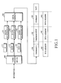
- FIG. 1 is a conceptual diagram illustrating a method for configuring a coded transmission symbol by coding and interleaving transmission information in a CDMA mobile communication system.
- FIG. 1 a description will now be made of a method for configuring a coded transmission symbol by coding and interleaving transmission information in a CDMA mobile communication system.
- Transmission information is input to a turbo encoder 100.
- constituent encoders included in the turbo encoder 100 generate parity information pairs using the transmission information, and use it as a redundancy. That is, the turbo encoder 100 outputs coded information U 111, which includes systematic bits that are output without being processed, a first parity symbol pair V0/V0' 112, and a second parity symbol pair V1/V1' 113.
- the parity symbol pairs 112 and 113 are double in size compared to the coded systematic symbols U 111.
- the systematic symbols U 111 are input to a first block interleaver 121
- the first parity symbol pair 112 is input to a second block interleaver 122
- the second parity symbol pair 113 is input to a third block interleaver 123. Because the symbols input to the interleavers are different in size, the second interleaver 122 and the third interleaver 123 are double in size compared to the first interleaver 121.
- the interleavers 121, 122 and 123 interleave their input symbols, and output the interleaved symbols to a serial combiner 130.
- the serial combiner 130 serially combines the output symbols of the block interleavers 121, 122 and 123, generating symbols 131, 132 and 133.
- the symbols generated by serial-combining (or concatenating) the independently interleaved symbols are divided into an initial transmission subpacket (or first transmission subpacket) 141, a primary retransmission subpacket (or second transmission subpacket) 142, and a secondary retransmission subpacket (or third transmission subpacket) 143 according to transmission time slot and slot size, and they are used for initial transmission, primary retransmission and secondary retransmission, respectively.
- the subpacket transmitted at initial transmission includes the coded interleaved symbols U 131 and a part of the coded interleaved first parity symbol pair V0/V0' 132.
- coded systematic symbols 131 and a part of the first parity symbol pair 132 constituting a redundancy are transmitted during the initial transmission.
- a part of the first parity symbol pair 132 constituting the redundancy is transmitted during the primary retransmission, and the remaining part of the first parity symbol pair 132 and a part of the second parity symbol pair 133, both constituting the redundancy, are transmitted during the secondary retransmission.
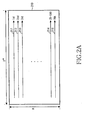
- FIGs. 2A through 2C are diagrams illustrating interleaving processes performed in the conventional CDMA system. The interleaving processes performed in the conventional CDMA system will now be described with reference to FIGs. 2A through 2C.
- Equation (1) a horizontal size of the block is denoted by 2 M and a vertical size of the block is denoted by R. As shown in Equation (1), the horizontal size is fixed to an exponential power of 2 and a value of R is determined such that the exponential power of 2 should be maximized.
- the first block interleaver 121 has a size of 3 ⁇ 210.
- the input order is determined as shown in FIG. 2A. More specifically, when the block is divided into rows and columns, the number of rows is R and the number of columns is 2 M . Therefore, the interleaver inputs coded symbols to a first row 211 among the R rows in a left-to-right direction, and after fully filling the first row 211 with the coded symbols, inputs coded symbols to the next row 212 in the left-to-right direction. This process is repeated until all of the R rows are filled with the coded symbols.
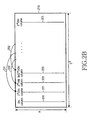
- FIG. 2B is a diagram illustrating a process of determining column positions on a BRO basis in a block interleaver.
- the BRO interleaving process includes:
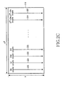
- FIG. 2C is a diagram illustrating an output (reading) order of symbols in a block interleaver after BRO-based column permutation.
- symbols are output column by column. That is, although the symbols are written (stored) row by row, the symbols are read (output) column by column.
- the columns are designated as 0 th column, 1 st column, 2 nd column, ⁇ in the left-to-right direction, symbols are output from the top to the bottom of the 0 th column. That is, the data is output in the order of columns denoted by reference numerals 220, 221, 222, 223, ⁇ , 224, 225.
- the symbols generated by serial-combining the coded interleaved symbols are modulated according to a predetermined modulation method before being transmitted.
- the modulation method may include Quadrature Phase Shift Keying (QPSK), 8-ary Phase Shift Keying (8PSK) and 16-ary Quadrature Amplitude Modulation (16QAM).
- QPSK Quadrature Phase Shift Keying
- 8PSK 8-ary Phase Shift Keying
- 16QAM 16-ary Quadrature Amplitude Modulation
- the modulation symbols differ from each other in symbol reliability according to modulation method used for the modulation.
- 8PSK or 16QAM modulated bits are different from each other in reliability. For example, if 3 interleaved bits 'b0,b1,b2' are mapped to one 8PSK symbol before being transmitted, the symbols 'b0,b1,b2' are not equal to each other in reliability.
- the symbol b2 is lower in reliability than the symbols b0 and b1.
- the symbols b 1 and b3 are lower in reliability than the symbols b0 and b2.
- the reliability is determined depending on a mapping method. Although the low-reliability bit positions can be improved by modifying the mapping method, the modification of the mapping method may cause a decrease in reliability of other symbol positions. That is, there are always some mapped bits whose transmission reliability is lower than that of the other bits.
- the bits interleaved by the conventional interleaver are mapped to a modulation symbol, adjacent bits might be mapped to the positions having the same reliability.
- the bits may be mapped to high-reliability positions in a particular interval, and to low-reliability positions in another interval, deteriorating channel coding performance. Therefore, during high-speed data transmission, a retransmission request may be frequently issued due to the low-reliability symbols.
- the service that cannot support retransmission such as broadcasting service, suffers QoS deterioration.
- a possible issuance of the retransmission request may result in a service delay and a reduction in channel resource efficiency.
- QoS quality-of-service
- a method for interleaving symbols coded by a turbo encoder is provided in a communication system that uses the turbo encoder for encoding transmission information into coded systematic symbols and at least one parity symbol pair, and maps the coded symbols using a second or higher modulation order before transmission.
- the method comprises defining, on a three-dimensional plane of x, y and z-axes, the modulation order as a size R of the z-axis, determining a size of the x-axis taking the size R of the z-axis into account so that a physical packet size of the transmission information has a maximum value of 2 M , and determining a size K of the y-axis so that the size K satisfies the physical packet size.
- the coded symbols are sequentially received, and the received coded symbols are three-dimensionally stored according to the sizes of the x, y and z-axes.
- the storing step comprises selecting an x-y plane in which an initial symbol is stored; sequentially storing the coded symbols in an x-z plane on the three-dimensional plane in a direction of the y-axis from a particular position in which the initial symbol is to be stored; after completion of storing the coded symbols in the y-axis direction, shifting in a direction of the x-axis from the particular position and then repeating the sequential storing step; and after completion of storing the coded symbols in the selected x-y plane, selecting a next x-y plane in a direction of the z-axis and repeating the sequential storing and shifting steps; after completion of storing the coded symbols received from the turbo encoder, independently performing cyclic shifting separately on the coded systematic symbols and the parity symbol pair for each x-z plane.
- an apparatus for interleaving symbols coded by a turbo encoder in a communication system that uses the turbo encoder for encoding transmission information into coded systematic symbols and at least one parity symbol pair, and maps the coded symbols using a second or higher modulation order before transmission.
- the apparatus includes an interleaver controller for receiving information on a size of a physical packet to be transmitted, the number of transmission slots and a modulation order, defining, on a three-dimensional plane of x, y and z-axes, the modulation order as a size R of the z-axis, determining a size of the x-axis taking the size R of the z-axis into account so that a physical packet size of the transmission information has a maximum value of 2 M , determining a size K of the y-axis so that the size K satisfies the physical packet size, storing the coded symbols in a three-dimensional interleaver, and controlling an interleaving and outputting operation.
- a channel interleaver sequentially receives the coded symbols, selecting, under the control of the interleaver controller, an x-y plane in which an initial symbol is to be stored according to sizes of the x, y and z-axes.
- the channel interleaver also sequentially stores the received symbols in an x-z plane on the three-dimensional plane in a direction of the y-axis from a particular position in which the initial symbol is to be stored.
- the channel interleaver shifts in a direction of the x-axis from the particular position and repeatedly sequentially stores the received symbols.
- the channel interleaver After completion of storing the coded symbols in the selected x-y plane, the channel interleaver selects a next x-y plane in a direction of the z-axis and stores all of the received symbols in the three-dimensional plane through repetition of the above process.
- the channel interleaver sets a value of 1/n to a value most approximating the value of m/p and setting the value of D to a value obtained by multiplying the value n by K.
- the channel interleaver divides y-z planes into columns and reorders the columns by bit reverse ordering (BRO), selecting an x-z plane, from which the symbols reordered in the x, y and z axes are to be output, according to the number of the coded symbols to be transmitted.
- BRO bit reverse ordering
- the channel interleaver determines an output order of y-z columns on the selected x-z plane, and sequentially outputs symbols in each of the determined columns in a direction of the z-axis.
- a method for interleaving symbols coded by a turbo encoder in a communication system that uses the turbo encoder for encoding transmission information into coded systematic symbols and at least one parity symbol pair, and maps the coded symbols using a second or higher modulation order before transmission is provided.
- the method comprises cyclic-shifting the systematic symbols among the symbols coded by the turbo encoder, using an equation of ( K ⁇ c + k ) mod R ; and cyclic-shifting redundancy symbols constituting the remaining size of the coded symbols to be transmitted, using an equation of floor ⁇ ( K ⁇ c + k )/ D ⁇ mod R ; wherein K denotes a height of symbols stored on a three-dimensional plane, c denotes a column index, k denotes a plane index having a value of 0, 1, ⁇ , R denotes a modulation order, mod denotes a modulo operation, floor x denotes a function indicating a largest integer not greater than x, and D denotes a parameter determined depending on the number of symbols to be transmitted.
- an apparatus for interleaving symbols coded by a turbo encoder in a communication system that uses the turbo encoder for encoding transmission information into coded systematic symbols and at least one parity symbol pair, and maps the coded symbols using a second or higher modulation order before transmission.
- the apparatus comprises an interleaver controller for performing a control operation of cyclic-shifting the systematic symbols among the symbols coded by the turbo encoder depending on a size of a physical packet to be transmitted, the number of transmission slots, and the modulation order, using an equation of ( K ⁇ c + k ) mod R , and cyclic-shifting redundancy symbols constituting the remaining size of the coded symbols to be transmitted, using an equation of floor ⁇ ( K ⁇ c + k )/ D ⁇ mod R ; and an interleaver for cyclic-shifting input symbols under the control of the interleaver controller; wherein K denotes a height of symbols stored on a three-dimensional plane, c denotes a column index, k denotes a plane index having a value of 0, 1, ⁇ , R denotes a modulation order, mod denotes a modulo operation, floor x denotes a function indicating a largest integer not greater than x, and D denotes a
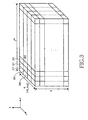
- FIG. 3 is a diagram illustrating an exemplary structure for storing coded symbols, given for a description of three-dimensional interleaving according to an embodiment of the present invention.
- FIG. 3 a description will now be made of a method for configuring coded symbols for three-dimensional interleaving according to an exemplary embodiment of the present invention.
- Equation (2) a horizontal size (the number of columns, or the number of symbols constituting the x-axis) is denoted by 2 M and a vertical size (the number of rows, or the number of symbols constituting the z-axis) is denoted by R.
- reference numerals 311, 321, 331, 341, 351 and 361 indicate the positions where symbols to be interleaved are stored, or the symbols to be interleaved. That is, each of hexahedrons in inner blocks constituting Equation (2) becomes one symbol storage position or one symbol.
- FIGs. 4A through 4D a description will now be made of a process in which symbols are stored and interleaved for three-dimensional interleaving.
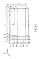
- FIG. 4A is a diagram illustrating a process of storing symbols for three-dimensional interleaving according to an exemplary embodiment of the present invention. With reference to FIG. 4A, a detailed description will now be made of a process of storing symbols for three-dimensional interleaving according to an embodiment of the present invention.
- FIG. 4A illustrates a first row on the z-axis selected from all blocks shown in FIG. 3.
- the first row is shown along with the y-axis in the three-dimensional block.
- symbols are input (written) in the top-to-bottom direction of the y-axis in the first row on the z-axis. That is, the symbols are stored in such a manner that a first symbol is stored in a position 311, the next symbols is stored in a position 312, and the next symbol is stored in a position 313. In this way, the final symbol on the y-axis is stored in a position 314.
- This symbol storage order is denoted by an arrow 411.
- next symbols are stored in the direction of an arrow 412.
- symbols are stored in the direction of an arrow 413 from the next position 331.
- a symbol storage direction is shown by a bold dotted line 421. Because the height is K, if a column is selected, K symbols are written in the column in the top-to-bottom direction of the y-axis. This process is repeated 2 M times. After symbols are completely stored in one of x-y planes in the foregoing manner, symbols are stored in the next x-y plane. Describing the order of x-y planes with reference to FIG. 3, x-y planes 311, 321 and 331 are first selected, and x-y planes 341, 351 and 361 are selected next. In this manner, the data is stored until the three-dimensional block is fully filled with data.
- FIG. 4B is a diagram for a description of a method for cyclic-shifting symbols for three-dimensional interleaving according to an exemplary embodiment of the present invention. With reference to FIG. 4B, a description will now be made of a cyclic shift operation according to an embodiment of the present invention.
- cyclic shifting in an exemplary embodiment of the present invention will be described in detail after a description of symbol outputting.
- a description will first be made of an operation of cyclic shifting of symbols.
- the cyclic shift operation determines the order or columns and then performs cyclic shifting on each of the columns.
- coded systematic symbols 111 are different from a first parity symbol pair 112 and a second parity symbol pair 113 in terms of a cyclic shift pattern.
- a cyclic shift pattern of the coded systematic symbols 111 is defined as Equation (3), and a cyclic shift pattern of the first parity symbol pair 112 and the second parity symbol pair 113 is defined as Equation (4).
- Cyclic Shift Pattern of Coded Systematic Symbols ( K ⁇ c + k ) mod R
- Cyclic Shift Pattern of Parity Symbols floor ⁇ ( K ⁇ c + k ) / D ⁇ mod R
- Equation (3) and Equation (4) K denotes a height of the three-dimensional block and R denotes a modulation order.
- c denotes a column index, that is, an order of a corresponding column
- k denotes an index corresponding to an x-z plane on the y-axis. Therefore, a value of D must be determined in order to determine a cyclic shift pattern for the parity symbol pairs. That is, D becomes a parameter used for determining a cyclic shift pattern.
- a method for performing cyclic shift in accordance with Equation (3) or Equation (4) performs z-axis cyclic shift in the manner shown by reference numerals 431 through 434.
- cyclic shift is not performed.
- symbols are down shifted one by one and the bottom symbol is shifted to the top.
- the top symbol is down shifted to a second symbol position, a third symbol is shifted to a first symbol position, and a fourth symbol is shifted to a second symbol position.
- this symbol shift operation is performed only in a corresponding x-z plane on the y-axis and a symbol shift operation in other x-z planes is performed in accordance with Equation (3) or Equation (4). Cyclic shift is accomplished according to the foregoing method. The reason for performing such a cyclic shift operation will be described in detail after a description of a method for outputting modulation symbols.
- FIG. 4C is a diagram illustrating a method for BRO-shifting three-dimensional interleaving symbols according to an embodiment of the present invention.
- a description will now be made of a method for BRO-shifting three-dimensional interleaving symbols according to an embodiment of the present invention.
- the BRO interleaving process includes:
- step a) the order of columns is determined as shown in FIG. 4C. That is, when the three-dimensional block is divided into y-z planes, a set of symbols constituting each of the planes becomes one column.
- step a) a decimal number indicating the order of a column is converted into a binary number.
- step b) the binary number is BRO-ordered.
- step c) the BRO-ordered binary number is re-converted into a decimal number.
- step d) all symbols in the corresponding column are shifted to a column indicated by the decimal number.
- arrows 451, 452 and 453 are provided to describe how to shift (permute) the columns.
- FIG. 4D is a diagram illustrating an output order of three-dimensional interleaving symbols according to an embodiment of the present invention.
- the symbol output process includes:
- Arrows 461 through 464 in FIG. 4D indicate step 3), an arrow 470 indicates step 2), and an arrow 480 indicates step 4).
- a horizontal size (the number of rows) denoted by the z-axis is set to a modulation order, such that columns output from the interleaver are mapped to one modulation symbol.
- s1 and s3 are located in high-reliability positions and s0 and s2 are located in low-reliability positions. Therefore, if an interleaver is implemented without the cyclic shift process, a first row where s0 is located and a third row where s2 is located are always mapped to low-reliability positions in the modulation symbol. Because coded symbols are input to the interleaver from the topmost x-z plane, the symbols in the same position on the y-axis are always mapped to the low-reliability positions. On the contrary, second and fourth columns where s1 and s3 are located, respectively, always have high reliability.
- an exemplary embodiment of the present invention can solve such problems by adopting a cyclic shifting method.
- the cyclic shift process cyclic-shifts positions of four different coded symbols located in one column.
- coded symbols s0, s1, s2 and s3 are mapped to one modulation symbol, and they are all located in the same column. Therefore, if a cyclic shift value, that is, the number of cyclic shifts, is 0 for the coded symbols, the position or output order of the cyclic-shifted coded symbols is maintained as s0, s1, s2 and s3.
- the cyclic shift value that is, the number of cyclic shifts
- the position or output order of the cyclic-shifted coded symbols becomes s3, s0, s 1 and s2. That is, s3 is located in a first row and s2 is located in a fourth row.
- the cyclic shift value is 2
- the position or output order of the cyclic-shifted coded symbols becomes s2, s3, s0 and s1
- the cyclic shift value is 3 the position or output order of the cyclic-shifted coded symbols becomes s1, s2, s3 and s0.
- one subpacket transmitted for one slot includes symbols of different contents at initial transmission, primary retransmission and secondary retransmission. That is, a subpacket including all of coded systematic symbols 131 and a part of a first parity symbol pair 132 is transmitted during initial transmission. In other words, only a part of the redundancy part is transmitted. Because only a leading part of the interleaved redundancy is transmitted, it is equivalent to puncturing some symbols among consecutive symbols before transmission, in a deinterleaving process.
- the number of cyclic shifts can be set to 0, 0, 1, 1, 2, 2, 3, 3, ⁇ . If the number of cyclic shifts is set in this way, even though only the odd symbols are transmitted, the number of cyclic shifts for the symbols is set to 0, 1, 2, 3, ⁇ , allowing adjacent bits to have different reliabilities. Specifically, if an i th symbol is mapped to a high-reliability position, an (i+1) th symbol is mapped to a low-reliability position, guaranteeing uniform reliability distribution.
- the number of cyclic shifts can be set to 0, 0, 0, 0, 1, 1, 1, 1, 2, 2, 2, 2, 3, 3, 3, 3, ⁇ .
- one parity symbol pair cannot be fully transmitted by simply transmitting only 1/n of the parity symbol pair and puncturing the remaining (n-1)/n of the parity symbol pair. That is, for n > m, m/n of one parity symbol pair may be transmitted and the remaining (n-m)/n may be punctured. In this case, for example, 7/16 of one parity symbol pair may be transmitted and the remaining 9/16 may be punctured.
- Such an irregular transmission pattern makes it difficult to find a value of D used for determining a cyclic shift pattern.
- the two methods can be performed in parallel. That is, it is also possible to select a value of 1/n that most approximates m/n. In this case, if m/n > 1/n, it is assumed that the number of punctured bits for m/n is less than the number of punctured bits for 1/n, and if m/n ⁇ 1/n, it is assumed that the number of punctured bits for m/n is greater than the number of punctured bits for 1/n.
- Table 1 illustrates an interleaving rule based on data rates and packet sizes available in a High Rate Packet Data (HRPD) system, which is a high-speed packet data transmission system, for data transmission.
- HRPD High Rate Packet Data
- Table 1 Physical packet size (U block size) 2048 3072 Transmit duration (slot) 1 1 Data rate 1.2Mbps 1.8Mbps Modulation 16QAM 16QAM Effective code rate 0.53 0.8 Transmitted Redundancy bit 1792 (7/16 of V0/V0' block) 768 (1/8 of V0/V0' block, 3/8 of 1 st level of V0/V0' block) R 4 4 M 9 8 K 1 3 D 2 6 (or 4)
- the interleaving parameters R, M, K and D are set depending on physical packet size. A description thereof will be made separately for each physical packet size.
- the number of redundancy symbols transmitted at initial transmission is 768.
- the physical packet size 3072 cannot be expressed as 2 M , a value of K is set to 3 so that it has three levels. That is, the three-dimensional block is configured to have three x-z planes on the y-axis. Therefore, each x-z plane constituting each level has 1024 symbols.
- the cyclic shift is repeated as "0, 1, 2, 0, 1, 2," and given that 1 st and 3 rd positions have high reliability in 16QAM, it can be considered that the cyclic shift values 2 and 0 are similar in performance. If a value of D is set to 4, the cyclic shift values become "0, 1, 3, 2, 3, 1". In this case also, 1 and 3 are adjacent to each other, and 3 occurs every other cyclic shift value. Therefore, it is preferable to set a value of D to 6. Setting a value of D to 4 is also a possible method, because 0 and 2 occurs alternately.
- the number of the redundancy symbols actually transmitted at initial transmission is calculated not from one parity symbol pair but from one level.
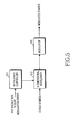
- FIG. 5 is a block diagram illustrating an apparatus for performing three-dimensional interleaving according to an exemplary embodiment of the present invention. With reference to FIG. 5, a detailed description will now be made of structure and operation of an apparatus for performing three-dimensional interleaving according to an embodiment of the present invention.
- the apparatus includes a turbo encoder 100 shown in FIG. 1.
- Coded symbols output from the turbo encoder 100 including coded systematic symbols 111, a first parity symbol pair 112 and a second parity symbol pair 113, are input to a three-dimensional interleaver 512 according to an exemplary embodiment of the present invention.
- the three-dimensional interleaver 512 like the block interleaver shown in FIG. 1, may include a first interleaver for interleaving the coded systematic symbols 111, a second interleaver for interleaving the first parity symbol pair 112, and a third interleaver for interleaving the second parity symbol pair 113. That is, the three-dimensional interleaver 512 also interleaves the coded systematic symbols 111 and the first and second parity symbol pairs 112 and 113 independently.
- the three-dimensional interleaver 512 performs interleaving under the control of an interleaver controller 511.
- the interleaver controller 511 receives such information as a physical packet size, the number of transmission slots, a modulation order, etc. Based on the received information, the interleaver controller 511 determines the parameters R, K, M and D for three-dimensional interleaving.
- the interleaver controller 511 controls an interleaving operation of the three-dimensional interleaver 512 based on values of the parameters. A detailed description of the control operation will be made later with reference to FIG. 6.
- the interleaver controller 511 can be replaced with a memory for storing parameter values mapped to each individual case. That is, the memory may store data rate, modulation order, the number of transmission slots, and physical packet size in the form of Table 1 or Table 2, read parameter values associated with them, and output the read parameter values to the three-dimensional interleaver 512.
- An embodiment of the present invention can be implemented with either of the methods. For convenience, it will be assumed herein that the interleaver controller 511 receives the parameter values and controls the three-dimensional interleaver 512 depending on the received parameter values.
- the three-dimensional interleaver 512 After completion of interleaving the received coded symbols under the control of the interleaver controller 511, the three-dimensional interleaver 512 outputs the interleaved symbols to a modulator 513 in the method described with reference to FIG. 4D. Then the modulator 513 maps the interleaved symbols received from the three-dimensional interleaver 512 according to a predetermined modulation order, and outputs modulated symbols.
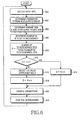
- FIG. 6 is a flowchart illustrating a three-dimensional interleaving operation according to an exemplary embodiment of the present invention. With reference to FIG. 6, a detailed description will now be made of a three-dimensional interleaving process according to an embodiment of the present invention.
- an interleaver controller 511 receives transmission data information.
- the data information may include a physical packet size, the number of transmission slots, a modulation order, a data rate, and so on.
- the interleaver controller 511 determines in step 602 a parameter R from the modulation order in the received data information. This is because, as described above, a value of the parameter R is determined depending on the modulation order.
- the interleaver controller 511 determines in step 604 parameters K and M from the physical packet size.
- the interleaver controller 511 can find a value that maximizes a value of M, from the data size, in order to perform three-dimensional interleaving. Thereafter, the interleaver controller 511 determines a value of the parameter K in order to match the number of interleaved symbols to the total number of symbols.
- the interleaver controller 511 determines the number of redundancy bits to be transmitted, in step 606. In other words, the interleaver controller 511 determines the number of parity symbols to be transmitted. Thereafter, in step 608, the interleaver controller 511 defines a value X by dividing the number of redundancy bits to be transmitted by the total number of redundancy bits.
- the interleaver controller 511 selects a value 1/n that most approximates the value X in step 614.
- the interleaver controller 511 selects a value 1/n most approximating the value X in FIG. 6 by way of example, the interleaver controller 511 can also select either a value 1/n that most approximates the value X and is greater than the value X, or a value 1/n that most approximates the value X and is less than the value X.
- the interleaver controller 511 determines in step 616 a value of the parameter D by multiplying the value n by the parameter K.
- the interleaver controller 511 After determining all of the parameters, the interleaver controller 511 provides the determined parameters to a three-dimensional interleaver 512 in step 620. Thereafter, in step 624, under the control of the interleaver controller 511, the three-dimensional interleaver 512 stores coded symbols, performs cyclic shift and BRO process on the coded symbols, and outputs the interleaved symbols. In other words, the three-dimensional interleaver 512 performs the interleaving process of FIGs. 4A through 4D.
- the use of the proposed three-dimensional interleaver can contribute to uniform reliability distribution for modulated symbols before being transmitted.
- an exemplary embodiment of the present invention can guarantee uniform reliability distribution for the modulated symbols before transmission, thereby increasing transmission efficiency.
Landscapes
- Engineering & Computer Science (AREA)
- Signal Processing (AREA)
- Computer Networks & Wireless Communication (AREA)
- Structural Engineering (AREA)
- Mining & Mineral Resources (AREA)
- Civil Engineering (AREA)
- General Engineering & Computer Science (AREA)
- Paleontology (AREA)
- Life Sciences & Earth Sciences (AREA)
- General Life Sciences & Earth Sciences (AREA)
- Error Detection And Correction (AREA)
- Detection And Prevention Of Errors In Transmission (AREA)
- Mobile Radio Communication Systems (AREA)
Applications Claiming Priority (1)
| Application Number | Priority Date | Filing Date | Title |
|---|---|---|---|
| KR20040099462 | 2004-11-30 |
Publications (3)
| Publication Number | Publication Date |
|---|---|
| EP1662687A2 true EP1662687A2 (de) | 2006-05-31 |
| EP1662687A3 EP1662687A3 (de) | 2012-05-02 |
| EP1662687B1 EP1662687B1 (de) | 2017-03-22 |
Family
ID=35686565
Family Applications (1)
| Application Number | Title | Priority Date | Filing Date |
|---|---|---|---|
| EP05026153.6A Expired - Lifetime EP1662687B1 (de) | 2004-11-30 | 2005-11-30 | Verfahren und Vorrichtung zur Kanalverschachtelung in einem Mobilfunksystem |
Country Status (9)
| Country | Link |
|---|---|
| US (1) | US7512843B2 (de) |
| EP (1) | EP1662687B1 (de) |
| JP (1) | JP4664985B2 (de) |
| KR (1) | KR101131323B1 (de) |
| CN (1) | CN101065910B (de) |
| AU (1) | AU2005310391B2 (de) |
| BR (1) | BRPI0518736B1 (de) |
| RU (1) | RU2349030C2 (de) |
| WO (1) | WO2006059871A1 (de) |
Cited By (1)
| Publication number | Priority date | Publication date | Assignee | Title |
|---|---|---|---|---|
| CN114760662A (zh) * | 2022-04-25 | 2022-07-15 | 北京星河亮点技术股份有限公司 | 一种低时延速率匹配方法、装置、电子设备及存储介质 |
Families Citing this family (16)
| Publication number | Priority date | Publication date | Assignee | Title |
|---|---|---|---|---|
| RU2261529C2 (ru) * | 2002-02-06 | 2005-09-27 | Самсунг Электроникс Ко.,Лтд | Перемежитель и способ перемежения в системе связи |
| US20090022079A1 (en) * | 2005-05-04 | 2009-01-22 | Fei Frank Zhou | Method and apparatus for providing enhanced channel interleaving |
| US7395461B2 (en) * | 2005-05-18 | 2008-07-01 | Seagate Technology Llc | Low complexity pseudo-random interleaver |
| CN101047393B (zh) * | 2006-05-12 | 2010-05-12 | 华为技术有限公司 | 一种产生交织器/解交织器的方法及其应用 |
| US8356234B2 (en) * | 2007-06-15 | 2013-01-15 | Samsung Electronics Co., Ltd. | Apparatus and method for transmitting and receiving data in a mobile communication system |
| CN101459432B (zh) * | 2007-12-14 | 2010-12-08 | 中兴通讯股份有限公司 | 一种rs码交织编码方法 |
| KR101182852B1 (ko) | 2008-03-10 | 2012-09-14 | 한국전자통신연구원 | 심볼 매핑 방법 및 장치 |
| JP5109787B2 (ja) * | 2008-05-02 | 2012-12-26 | 富士通株式会社 | データ伝送システム、プログラム及び方法 |
| KR101509728B1 (ko) * | 2008-06-05 | 2015-04-06 | 한국전자통신연구원 | 심볼 매핑 방법 및 장치 |
| US8468396B2 (en) | 2008-12-31 | 2013-06-18 | Mediatek, Inc. | Channel interleaver having a constellation-based block-wise permuation module |
| WO2010105445A1 (zh) * | 2009-03-20 | 2010-09-23 | 富士通株式会社 | 信道交织方法和信道交织器 |
| US8638244B2 (en) * | 2009-08-31 | 2014-01-28 | Freescale Semiconductor, Inc. | Encoding module, apparatus and method for determining a position of a data bit within an interleaved data stream |
| CN102130757B (zh) * | 2010-01-19 | 2015-07-29 | 北京三星通信技术研究有限公司 | 交织重传装置及方法 |
| KR101146987B1 (ko) | 2010-05-03 | 2012-05-23 | 삼성모바일디스플레이주식회사 | 표시장치 및 표시장치에 구비된 구동칩실장용필름소자 |
| WO2015126096A1 (en) * | 2014-02-21 | 2015-08-27 | Samsung Electronics Co., Ltd. | Bit interleaver and bit de-interleaver |
| US11515970B2 (en) * | 2020-12-04 | 2022-11-29 | Qualcomm Incorporated | Priority-based hybrid automatic repeat request acknowledgement (HARQ-ACK) feedback |
Family Cites Families (30)
| Publication number | Priority date | Publication date | Assignee | Title |
|---|---|---|---|---|
| US5721745A (en) | 1996-04-19 | 1998-02-24 | General Electric Company | Parallel concatenated tail-biting convolutional code and decoder therefor |
| RU2210185C2 (ru) | 1998-03-31 | 2003-08-10 | Самсунг Электроникс Ко., Лтд. | Устройство и способ турбокодирования/декодирования для обработки данных кадра в соответствии с качеством обслуживания |
| US6298463B1 (en) * | 1998-07-31 | 2001-10-02 | Nortel Networks Limited | Parallel concatenated convolutional coding |
| EP2173036B1 (de) * | 1998-08-17 | 2014-05-14 | Dtvg Licensing, Inc | Verschachteler für Turbo-kode mit annäherender optimaler Leistung |
| US6427214B1 (en) * | 1998-09-29 | 2002-07-30 | Nortel Networks Limited | Interleaver using co-set partitioning |
| US6772391B1 (en) * | 1998-10-13 | 2004-08-03 | Interdigital Technology Corporation | Hybrid interleaver for turbo codes |
| JP3257984B2 (ja) * | 1998-10-30 | 2002-02-18 | 富士通株式会社 | インタリーブ方法及びデインタリーブ方法並びにインタリーブ装置及びデインタリーブ装置並びにインタリーブ/デインタリーブシステム並びにインタリーブ/デインタリーブ装置並びにインタリーブ機能付きの送信装置,デインタリーブ機能付きの受信装置及びインタリーブ/デインタリーブ機能付きの送受信装置 |
| US6304991B1 (en) * | 1998-12-04 | 2001-10-16 | Qualcomm Incorporated | Turbo code interleaver using linear congruential sequence |
| KR100350459B1 (ko) * | 1998-12-26 | 2002-12-26 | 삼성전자 주식회사 | 통신시스템의인터리빙/디인터리빙장치및방법 |
| CA2298919C (en) * | 1999-02-19 | 2006-04-18 | Ntt Mobile Communications Network Inc. | Interleaving and turbo encoding using prime number permutations |
| DK1097516T3 (da) * | 1999-05-19 | 2007-01-29 | Samsung Electronics Co Ltd | Apparat og fremgangsmåde til turbo-interleaving |
| DE10030407B4 (de) * | 1999-07-14 | 2011-09-01 | Lg Electronics Inc. | Verfahren zur optimalen Ratenanpassung in einem Mobilkommunikationssystem |
| KR100393608B1 (ko) * | 2000-09-29 | 2003-08-09 | 삼성전자주식회사 | 유.엠.티.에스시스템내 터보부호화기의 내부 인터리버 및인터리빙 수행 방법 |
| KR100724921B1 (ko) * | 2001-02-16 | 2007-06-04 | 삼성전자주식회사 | 통신시스템에서 부호 생성 및 복호 장치 및 방법 |
| US6845482B2 (en) * | 2001-02-28 | 2005-01-18 | Qualcomm Incorporated | Interleaver for turbo decoder |
| KR100753309B1 (ko) | 2001-04-10 | 2007-08-29 | 주식회사 팬택앤큐리텔 | 3지피피 비동기 시스템에서 세컨드 인터리빙을 위한변조장치 |
| US7278070B2 (en) * | 2001-09-14 | 2007-10-02 | Texas Instruments Incorporated | Interleaving to avoid wideband interference in a multi-carrier communications system |
| JP3624874B2 (ja) * | 2001-11-19 | 2005-03-02 | 日本電気株式会社 | インターリービング順序発生器、インターリーバ、ターボエンコーダ、及びターボデコーダ |
| JP3753072B2 (ja) * | 2002-01-16 | 2006-03-08 | 日本ビクター株式会社 | 直交周波数分割多重信号の生成方法、直交周波数分割多重信号生成装置、及び直交周波数分割多重信号復号装置 |
| KR100475185B1 (ko) | 2002-01-30 | 2005-03-08 | 삼성전자주식회사 | 에이치디알 전송장치의 인터리버 및 그 인터리빙 방법 |
| RU2261529C2 (ru) * | 2002-02-06 | 2005-09-27 | Самсунг Электроникс Ко.,Лтд | Перемежитель и способ перемежения в системе связи |
| US7082168B2 (en) * | 2002-05-21 | 2006-07-25 | Coffey John T | Methods and apparatus for self-inverting turbo code interleaving with high separation and dispersion |
| US7085985B2 (en) * | 2002-05-31 | 2006-08-01 | Broadcom Corporation | Close two constituent trellis of a turbo encoder within the interleave block |
| JP2004152551A (ja) * | 2002-10-29 | 2004-05-27 | Kyocera Corp | 銅メタライズ組成物、並びにセラミック配線基板およびその製法 |
| CN1204693C (zh) * | 2002-11-29 | 2005-06-01 | 重庆重邮信科股份有限公司 | 随机系统Turbo码的编、译码方法 |
| CA2507620C (en) * | 2002-12-16 | 2014-04-15 | Telecom Italia S.P.A. | Addresses generation for interleavers in turbo encoders and decoders |
| US7085986B2 (en) * | 2002-12-20 | 2006-08-01 | Nokia Corporation | Low decoding complexity concatenated codes for high rate coded transmission |
| US7702968B2 (en) * | 2004-02-27 | 2010-04-20 | Qualcomm Incorporated | Efficient multi-symbol deinterleaver |
| JP2006086941A (ja) * | 2004-09-17 | 2006-03-30 | Matsushita Electric Ind Co Ltd | 送信方法と送信装置及び受信方法と受信装置 |
| US7593472B2 (en) * | 2004-10-22 | 2009-09-22 | Integrated System Solution Corp. | Methods and apparatus for circulation transmissions for OFDM-based MIMO systems |
-
2005
- 2005-01-04 KR KR20050000648A patent/KR101131323B1/ko not_active Expired - Fee Related
- 2005-11-30 WO PCT/KR2005/004072 patent/WO2006059871A1/en not_active Ceased
- 2005-11-30 CN CN2005800408861A patent/CN101065910B/zh not_active Expired - Fee Related
- 2005-11-30 US US11/289,570 patent/US7512843B2/en active Active
- 2005-11-30 JP JP2007544263A patent/JP4664985B2/ja not_active Expired - Fee Related
- 2005-11-30 RU RU2007116510A patent/RU2349030C2/ru not_active IP Right Cessation
- 2005-11-30 AU AU2005310391A patent/AU2005310391B2/en not_active Ceased
- 2005-11-30 EP EP05026153.6A patent/EP1662687B1/de not_active Expired - Lifetime
- 2005-11-30 BR BRPI0518736-2A patent/BRPI0518736B1/pt not_active IP Right Cessation
Non-Patent Citations (1)
| Title |
|---|
| None |
Cited By (1)
| Publication number | Priority date | Publication date | Assignee | Title |
|---|---|---|---|---|
| CN114760662A (zh) * | 2022-04-25 | 2022-07-15 | 北京星河亮点技术股份有限公司 | 一种低时延速率匹配方法、装置、电子设备及存储介质 |
Also Published As
| Publication number | Publication date |
|---|---|
| KR101131323B1 (ko) | 2012-04-04 |
| AU2005310391B2 (en) | 2008-09-25 |
| EP1662687A3 (de) | 2012-05-02 |
| CN101065910B (zh) | 2011-01-26 |
| US7512843B2 (en) | 2009-03-31 |
| US20060156172A1 (en) | 2006-07-13 |
| BRPI0518736A2 (pt) | 2008-12-02 |
| BRPI0518736B1 (pt) | 2019-04-09 |
| AU2005310391A1 (en) | 2006-06-08 |
| JP2008522539A (ja) | 2008-06-26 |
| KR20060060520A (ko) | 2006-06-05 |
| RU2007116510A (ru) | 2008-11-20 |
| RU2349030C2 (ru) | 2009-03-10 |
| WO2006059871A1 (en) | 2006-06-08 |
| CN101065910A (zh) | 2007-10-31 |
| EP1662687B1 (de) | 2017-03-22 |
| JP4664985B2 (ja) | 2011-04-06 |
Similar Documents
| Publication | Publication Date | Title |
|---|---|---|
| US7512843B2 (en) | Apparatus and method for interleaving channels in a mobile communication system | |
| RU2604992C2 (ru) | Устройство, содержащее кольцевой буфер и способ для присвоения вариантов избыточности кольцевому буферу | |
| KR100827147B1 (ko) | 부호분할다중접속 이동통신시스템에서 고속 데이터의효율적 재전송 및 복호화를 위한 송,수신장치 및 방법 | |
| KR101505193B1 (ko) | 직교주파수분할다중접속방식의 이동 통신시스템에서 심볼전송 방법 및 장치 | |
| EP1545036B1 (de) | Vorrichtung und Verfahren für Kodegenerierung in einem Kommunikationssystem | |
| US7260770B2 (en) | Block puncturing for turbo code based incremental redundancy | |
| RU2237977C2 (ru) | Передача пакетных данных в системе мобильной связи | |
| CN100514900C (zh) | 使用比特排列方法的传输装置 | |
| US8677204B2 (en) | Methods and apparatus for transmitting/receiving data in a communication system | |
| CN101183875B (zh) | 一种Turbo码的有限长度循环缓存的速率匹配方法 | |
| US20030088822A1 (en) | Transmission/reception apparatus and method for packet retransmission in a CDMA mobile communication system | |
| US8798200B2 (en) | Constellation mapping method | |
| KR20030010074A (ko) | 부호분할다중접속 이동통신시스템에서 고속 데이터의 재전송장치 및 방법 | |
| US7702970B2 (en) | Method and apparatus for deinterleaving interleaved data stream in a communication system | |
| US7213193B2 (en) | Apparatus and method for generating codes in a communications system | |
| US20050050427A1 (en) | Method of rate matching for link adaptation and code space management | |
| GB2394153A (en) | A Quasi-Complementary Turbo Code (QCTC) generating apparatus |
Legal Events
| Date | Code | Title | Description |
|---|---|---|---|
| PUAI | Public reference made under article 153(3) epc to a published international application that has entered the european phase |
Free format text: ORIGINAL CODE: 0009012 |
|
| 17P | Request for examination filed |
Effective date: 20051130 |
|
| AK | Designated contracting states |
Kind code of ref document: A2 Designated state(s): AT BE BG CH CY CZ DE DK EE ES FI FR GB GR HU IE IS IT LI LT LU LV MC NL PL PT RO SE SI SK TR |
|
| AX | Request for extension of the european patent |
Extension state: AL BA HR MK YU |
|
| PUAL | Search report despatched |
Free format text: ORIGINAL CODE: 0009013 |
|
| RIC1 | Information provided on ipc code assigned before grant |
Ipc: H04L 1/00 20060101AFI20120312BHEP |
|
| AK | Designated contracting states |
Kind code of ref document: A3 Designated state(s): AT BE BG CH CY CZ DE DK EE ES FI FR GB GR HU IE IS IT LI LT LU LV MC NL PL PT RO SE SI SK TR |
|
| AX | Request for extension of the european patent |
Extension state: AL BA HR MK YU |
|
| RIC1 | Information provided on ipc code assigned before grant |
Ipc: H04L 1/00 20060101AFI20120326BHEP |
|
| RAP1 | Party data changed (applicant data changed or rights of an application transferred) |
Owner name: SAMSUNG ELECTRONICS CO., LTD. |
|
| AKX | Designation fees paid |
Designated state(s): AT BE BG CH CY CZ DE DK EE ES FI FR GB GR HU IE IS IT LI LT LU LV MC NL PL PT RO SE SI SK TR |
|
| GRAP | Despatch of communication of intention to grant a patent |
Free format text: ORIGINAL CODE: EPIDOSNIGR1 |
|
| INTG | Intention to grant announced |
Effective date: 20160906 |
|
| GRAS | Grant fee paid |
Free format text: ORIGINAL CODE: EPIDOSNIGR3 |
|
| GRAA | (expected) grant |
Free format text: ORIGINAL CODE: 0009210 |
|
| AK | Designated contracting states |
Kind code of ref document: B1 Designated state(s): AT BE BG CH CY CZ DE DK EE ES FI FR GB GR HU IE IS IT LI LT LU LV MC NL PL PT RO SE SI SK TR |
|
| REG | Reference to a national code |
Ref country code: GB Ref legal event code: FG4D |
|
| REG | Reference to a national code |
Ref country code: CH Ref legal event code: EP |
|
| REG | Reference to a national code |
Ref country code: AT Ref legal event code: REF Ref document number: 878698 Country of ref document: AT Kind code of ref document: T Effective date: 20170415 |
|
| REG | Reference to a national code |
Ref country code: IE Ref legal event code: FG4D |
|
| REG | Reference to a national code |
Ref country code: DE Ref legal event code: R096 Ref document number: 602005051553 Country of ref document: DE |
|
| REG | Reference to a national code |
Ref country code: NL Ref legal event code: MP Effective date: 20170322 |
|
| PG25 | Lapsed in a contracting state [announced via postgrant information from national office to epo] |
Ref country code: GR Free format text: LAPSE BECAUSE OF FAILURE TO SUBMIT A TRANSLATION OF THE DESCRIPTION OR TO PAY THE FEE WITHIN THE PRESCRIBED TIME-LIMIT Effective date: 20170623 Ref country code: LT Free format text: LAPSE BECAUSE OF FAILURE TO SUBMIT A TRANSLATION OF THE DESCRIPTION OR TO PAY THE FEE WITHIN THE PRESCRIBED TIME-LIMIT Effective date: 20170322 Ref country code: FI Free format text: LAPSE BECAUSE OF FAILURE TO SUBMIT A TRANSLATION OF THE DESCRIPTION OR TO PAY THE FEE WITHIN THE PRESCRIBED TIME-LIMIT Effective date: 20170322 |
|
| REG | Reference to a national code |
Ref country code: LT Ref legal event code: MG4D |
|
| REG | Reference to a national code |
Ref country code: AT Ref legal event code: MK05 Ref document number: 878698 Country of ref document: AT Kind code of ref document: T Effective date: 20170322 |
|
| PG25 | Lapsed in a contracting state [announced via postgrant information from national office to epo] |
Ref country code: SE Free format text: LAPSE BECAUSE OF FAILURE TO SUBMIT A TRANSLATION OF THE DESCRIPTION OR TO PAY THE FEE WITHIN THE PRESCRIBED TIME-LIMIT Effective date: 20170322 Ref country code: LV Free format text: LAPSE BECAUSE OF FAILURE TO SUBMIT A TRANSLATION OF THE DESCRIPTION OR TO PAY THE FEE WITHIN THE PRESCRIBED TIME-LIMIT Effective date: 20170322 Ref country code: BG Free format text: LAPSE BECAUSE OF FAILURE TO SUBMIT A TRANSLATION OF THE DESCRIPTION OR TO PAY THE FEE WITHIN THE PRESCRIBED TIME-LIMIT Effective date: 20170622 |
|
| PG25 | Lapsed in a contracting state [announced via postgrant information from national office to epo] |
Ref country code: NL Free format text: LAPSE BECAUSE OF FAILURE TO SUBMIT A TRANSLATION OF THE DESCRIPTION OR TO PAY THE FEE WITHIN THE PRESCRIBED TIME-LIMIT Effective date: 20170322 |
|
| PG25 | Lapsed in a contracting state [announced via postgrant information from national office to epo] |
Ref country code: RO Free format text: LAPSE BECAUSE OF FAILURE TO SUBMIT A TRANSLATION OF THE DESCRIPTION OR TO PAY THE FEE WITHIN THE PRESCRIBED TIME-LIMIT Effective date: 20170322 Ref country code: SK Free format text: LAPSE BECAUSE OF FAILURE TO SUBMIT A TRANSLATION OF THE DESCRIPTION OR TO PAY THE FEE WITHIN THE PRESCRIBED TIME-LIMIT Effective date: 20170322 Ref country code: AT Free format text: LAPSE BECAUSE OF FAILURE TO SUBMIT A TRANSLATION OF THE DESCRIPTION OR TO PAY THE FEE WITHIN THE PRESCRIBED TIME-LIMIT Effective date: 20170322 Ref country code: ES Free format text: LAPSE BECAUSE OF FAILURE TO SUBMIT A TRANSLATION OF THE DESCRIPTION OR TO PAY THE FEE WITHIN THE PRESCRIBED TIME-LIMIT Effective date: 20170322 Ref country code: IT Free format text: LAPSE BECAUSE OF FAILURE TO SUBMIT A TRANSLATION OF THE DESCRIPTION OR TO PAY THE FEE WITHIN THE PRESCRIBED TIME-LIMIT Effective date: 20170322 Ref country code: CZ Free format text: LAPSE BECAUSE OF FAILURE TO SUBMIT A TRANSLATION OF THE DESCRIPTION OR TO PAY THE FEE WITHIN THE PRESCRIBED TIME-LIMIT Effective date: 20170322 Ref country code: EE Free format text: LAPSE BECAUSE OF FAILURE TO SUBMIT A TRANSLATION OF THE DESCRIPTION OR TO PAY THE FEE WITHIN THE PRESCRIBED TIME-LIMIT Effective date: 20170322 |
|
| PG25 | Lapsed in a contracting state [announced via postgrant information from national office to epo] |
Ref country code: PT Free format text: LAPSE BECAUSE OF FAILURE TO SUBMIT A TRANSLATION OF THE DESCRIPTION OR TO PAY THE FEE WITHIN THE PRESCRIBED TIME-LIMIT Effective date: 20170724 Ref country code: IS Free format text: LAPSE BECAUSE OF FAILURE TO SUBMIT A TRANSLATION OF THE DESCRIPTION OR TO PAY THE FEE WITHIN THE PRESCRIBED TIME-LIMIT Effective date: 20170722 Ref country code: PL Free format text: LAPSE BECAUSE OF FAILURE TO SUBMIT A TRANSLATION OF THE DESCRIPTION OR TO PAY THE FEE WITHIN THE PRESCRIBED TIME-LIMIT Effective date: 20170322 |
|
| REG | Reference to a national code |
Ref country code: DE Ref legal event code: R097 Ref document number: 602005051553 Country of ref document: DE |
|
| PLBE | No opposition filed within time limit |
Free format text: ORIGINAL CODE: 0009261 |
|
| STAA | Information on the status of an ep patent application or granted ep patent |
Free format text: STATUS: NO OPPOSITION FILED WITHIN TIME LIMIT |
|
| PG25 | Lapsed in a contracting state [announced via postgrant information from national office to epo] |
Ref country code: DK Free format text: LAPSE BECAUSE OF FAILURE TO SUBMIT A TRANSLATION OF THE DESCRIPTION OR TO PAY THE FEE WITHIN THE PRESCRIBED TIME-LIMIT Effective date: 20170322 |
|
| 26N | No opposition filed |
Effective date: 20180102 |
|
| PG25 | Lapsed in a contracting state [announced via postgrant information from national office to epo] |
Ref country code: SI Free format text: LAPSE BECAUSE OF FAILURE TO SUBMIT A TRANSLATION OF THE DESCRIPTION OR TO PAY THE FEE WITHIN THE PRESCRIBED TIME-LIMIT Effective date: 20170322 |
|
| PG25 | Lapsed in a contracting state [announced via postgrant information from national office to epo] |
Ref country code: MC Free format text: LAPSE BECAUSE OF FAILURE TO SUBMIT A TRANSLATION OF THE DESCRIPTION OR TO PAY THE FEE WITHIN THE PRESCRIBED TIME-LIMIT Effective date: 20170322 |
|
| PG25 | Lapsed in a contracting state [announced via postgrant information from national office to epo] |
Ref country code: LI Free format text: LAPSE BECAUSE OF NON-PAYMENT OF DUE FEES Effective date: 20171130 Ref country code: CH Free format text: LAPSE BECAUSE OF NON-PAYMENT OF DUE FEES Effective date: 20171130 |
|
| PG25 | Lapsed in a contracting state [announced via postgrant information from national office to epo] |
Ref country code: LU Free format text: LAPSE BECAUSE OF NON-PAYMENT OF DUE FEES Effective date: 20171130 |
|
| REG | Reference to a national code |
Ref country code: FR Ref legal event code: ST Effective date: 20180731 Ref country code: BE Ref legal event code: MM Effective date: 20171130 |
|
| REG | Reference to a national code |
Ref country code: IE Ref legal event code: MM4A |
|
| PG25 | Lapsed in a contracting state [announced via postgrant information from national office to epo] |
Ref country code: FR Free format text: LAPSE BECAUSE OF NON-PAYMENT OF DUE FEES Effective date: 20171130 Ref country code: IE Free format text: LAPSE BECAUSE OF NON-PAYMENT OF DUE FEES Effective date: 20171130 |
|
| PG25 | Lapsed in a contracting state [announced via postgrant information from national office to epo] |
Ref country code: BE Free format text: LAPSE BECAUSE OF NON-PAYMENT OF DUE FEES Effective date: 20171130 |
|
| PG25 | Lapsed in a contracting state [announced via postgrant information from national office to epo] |
Ref country code: HU Free format text: LAPSE BECAUSE OF FAILURE TO SUBMIT A TRANSLATION OF THE DESCRIPTION OR TO PAY THE FEE WITHIN THE PRESCRIBED TIME-LIMIT; INVALID AB INITIO Effective date: 20051130 |
|
| PG25 | Lapsed in a contracting state [announced via postgrant information from national office to epo] |
Ref country code: CY Free format text: LAPSE BECAUSE OF NON-PAYMENT OF DUE FEES Effective date: 20170322 |
|
| PG25 | Lapsed in a contracting state [announced via postgrant information from national office to epo] |
Ref country code: TR Free format text: LAPSE BECAUSE OF FAILURE TO SUBMIT A TRANSLATION OF THE DESCRIPTION OR TO PAY THE FEE WITHIN THE PRESCRIBED TIME-LIMIT Effective date: 20170322 |
|
| PGFP | Annual fee paid to national office [announced via postgrant information from national office to epo] |
Ref country code: GB Payment date: 20191023 Year of fee payment: 15 |
|
| GBPC | Gb: european patent ceased through non-payment of renewal fee |
Effective date: 20201130 |
|
| PG25 | Lapsed in a contracting state [announced via postgrant information from national office to epo] |
Ref country code: GB Free format text: LAPSE BECAUSE OF NON-PAYMENT OF DUE FEES Effective date: 20201130 |
|
| PGFP | Annual fee paid to national office [announced via postgrant information from national office to epo] |
Ref country code: DE Payment date: 20241021 Year of fee payment: 20 |
|
| REG | Reference to a national code |
Ref country code: DE Ref legal event code: R071 Ref document number: 602005051553 Country of ref document: DE |