EP1661833B1 - Verfahren und Vorrichtung zum Verarbeiten von Druckereierzeugnissen - Google Patents
Verfahren und Vorrichtung zum Verarbeiten von Druckereierzeugnissen Download PDFInfo
- Publication number
- EP1661833B1 EP1661833B1 EP05021602A EP05021602A EP1661833B1 EP 1661833 B1 EP1661833 B1 EP 1661833B1 EP 05021602 A EP05021602 A EP 05021602A EP 05021602 A EP05021602 A EP 05021602A EP 1661833 B1 EP1661833 B1 EP 1661833B1
- Authority
- EP
- European Patent Office
- Prior art keywords
- processing
- printed
- thickness
- measuring
- control device
- Prior art date
- Legal status (The legal status is an assumption and is not a legal conclusion. Google has not performed a legal analysis and makes no representation as to the accuracy of the status listed.)
- Expired - Lifetime
Links
Images


Classifications
-
- B—PERFORMING OPERATIONS; TRANSPORTING
- B65—CONVEYING; PACKING; STORING; HANDLING THIN OR FILAMENTARY MATERIAL
- B65H—HANDLING THIN OR FILAMENTARY MATERIAL, e.g. SHEETS, WEBS, CABLES
- B65H7/00—Controlling article feeding, separating, pile-advancing, or associated apparatus, to take account of incorrect feeding, absence of articles, or presence of faulty articles
- B65H7/02—Controlling article feeding, separating, pile-advancing, or associated apparatus, to take account of incorrect feeding, absence of articles, or presence of faulty articles by feelers or detectors
- B65H7/14—Controlling article feeding, separating, pile-advancing, or associated apparatus, to take account of incorrect feeding, absence of articles, or presence of faulty articles by feelers or detectors by photoelectric feelers or detectors
-
- B—PERFORMING OPERATIONS; TRANSPORTING
- B65—CONVEYING; PACKING; STORING; HANDLING THIN OR FILAMENTARY MATERIAL
- B65H—HANDLING THIN OR FILAMENTARY MATERIAL, e.g. SHEETS, WEBS, CABLES
- B65H29/00—Delivering or advancing articles from machines; Advancing articles to or into piles
- B65H29/003—Delivering or advancing articles from machines; Advancing articles to or into piles by grippers
-
- B—PERFORMING OPERATIONS; TRANSPORTING
- B65—CONVEYING; PACKING; STORING; HANDLING THIN OR FILAMENTARY MATERIAL
- B65H—HANDLING THIN OR FILAMENTARY MATERIAL, e.g. SHEETS, WEBS, CABLES
- B65H29/00—Delivering or advancing articles from machines; Advancing articles to or into piles
- B65H29/66—Advancing articles in overlapping streams
- B65H29/6609—Advancing articles in overlapping streams forming an overlapping stream
- B65H29/6618—Advancing articles in overlapping streams forming an overlapping stream upon transfer from a first conveyor to a second conveyor advancing at slower speed
-
- B—PERFORMING OPERATIONS; TRANSPORTING
- B65—CONVEYING; PACKING; STORING; HANDLING THIN OR FILAMENTARY MATERIAL
- B65H—HANDLING THIN OR FILAMENTARY MATERIAL, e.g. SHEETS, WEBS, CABLES
- B65H7/00—Controlling article feeding, separating, pile-advancing, or associated apparatus, to take account of incorrect feeding, absence of articles, or presence of faulty articles
- B65H7/20—Controlling associated apparatus
-
- B—PERFORMING OPERATIONS; TRANSPORTING
- B65—CONVEYING; PACKING; STORING; HANDLING THIN OR FILAMENTARY MATERIAL
- B65H—HANDLING THIN OR FILAMENTARY MATERIAL, e.g. SHEETS, WEBS, CABLES
- B65H2511/00—Dimensions; Position; Numbers; Identification; Occurrences
- B65H2511/10—Size; Dimensions
- B65H2511/13—Thickness
-
- B—PERFORMING OPERATIONS; TRANSPORTING
- B65—CONVEYING; PACKING; STORING; HANDLING THIN OR FILAMENTARY MATERIAL
- B65H—HANDLING THIN OR FILAMENTARY MATERIAL, e.g. SHEETS, WEBS, CABLES
- B65H2511/00—Dimensions; Position; Numbers; Identification; Occurrences
- B65H2511/20—Location in space
- B65H2511/21—Angle
- B65H2511/212—Rotary position
-
- B—PERFORMING OPERATIONS; TRANSPORTING
- B65—CONVEYING; PACKING; STORING; HANDLING THIN OR FILAMENTARY MATERIAL
- B65H—HANDLING THIN OR FILAMENTARY MATERIAL, e.g. SHEETS, WEBS, CABLES
- B65H2513/00—Dynamic entities; Timing aspects
- B65H2513/50—Timing
-
- B—PERFORMING OPERATIONS; TRANSPORTING
- B65—CONVEYING; PACKING; STORING; HANDLING THIN OR FILAMENTARY MATERIAL
- B65H—HANDLING THIN OR FILAMENTARY MATERIAL, e.g. SHEETS, WEBS, CABLES
- B65H2553/00—Sensing or detecting means
- B65H2553/40—Sensing or detecting means using optical, e.g. photographic, elements
- B65H2553/41—Photoelectric detectors
- B65H2553/412—Photoelectric detectors in barrier arrangements, i.e. emitter facing a receptor element
-
- B—PERFORMING OPERATIONS; TRANSPORTING
- B65—CONVEYING; PACKING; STORING; HANDLING THIN OR FILAMENTARY MATERIAL
- B65H—HANDLING THIN OR FILAMENTARY MATERIAL, e.g. SHEETS, WEBS, CABLES
- B65H2553/00—Sensing or detecting means
- B65H2553/40—Sensing or detecting means using optical, e.g. photographic, elements
- B65H2553/41—Photoelectric detectors
- B65H2553/414—Photoelectric detectors involving receptor receiving light reflected by a reflecting surface and emitted by a separate emitter
Definitions
- the present invention relates to a method and a device for processing printed products according to the preamble of patent claims 1 and 5, respectively.
- EP-A-0 897 887 and EP-A-0 479 717 known.
- a thickness measuring device By means of a thickness measuring device, the thickness of each printed by a conveyor to her transported printed products. A measuring signal generated thereby is fed to a control device which compares the measuring signal with a desired range for checking the thickness of the printed products. If the measured thickness of a printed product is outside the tolerance range, this is assessed as incomplete or as defective and eliminated.
- EP-A-1 148 007 discloses a device for removing printed on a conveyor at regular intervals printed products. It has a rotatably driven gripping device with gripping means, which detects a printed product on the conveyor and lifts it in a stable position. Control means for a closing and opening movement of the gripping means are adjustable to adapt to a previously measured thickness of the printed products in the barrel.
- This will be manual intervention, such as adjustments and adjustments, avoided at the processing device, for example, in the conversion of the processing of printed matter of certain thickness on printed matter of different thickness or in the processing of printed matter of different thickness.
- the in the FIG. 1 The device shown has a conveyor 10 designed as a staple conveyor.
- staple transporters are well known. They have a arranged in a guide channel conveying member 12 which is driven in the conveying direction F at a conveying speed v1 circumferentially, and on which at regular intervals one behind the other transport clamps 14 are arranged. I'm in the FIG. 1
- the conveying clamps 14 are intended to hold and transport a printed product 18 with their two clamp tongues 16 forming a clamp mouth.
- Denoted at 20 is a release device associated with the delivery device 10, which is intended to open the clamp mouth of the transport clamps 14 moved past it in the activated state, so that the relevant printed products 18 are transported suspended at the release device 20.
- the triggering device 20 does not act on the transport clamps 14 moved past it, so that then at the triggering device 20 no printed products 18 are released and these are conveyed further by means of the conveying device 10.
- the conveyor 10 is associated with a measuring device 22 for measuring the thickness D of the printed products 18.
- a thickness gauge 24 which below in connection with the FIGS. 2 and 3 be described in more detail and to a signal processing unit 26, at the passage of each transport bracket 14, Emits sensor signals.
- the sensor signals generated as a function of the thickness of the printed products 18 guided past the thickness measuring arrangement 24 are processed in the signal conditioning unit 26 to form a measuring signal 28 which, as indicated by the dot-dash line, is fed to a control device 30.
- the control device 30 controls a packaging machine 34 which serves as a processing device 32. It has an infeed belt conveyor 36, which is driven in the same conveying direction F as the conveying device 10 and at a speed v2. An upstream end portion 38 of the infeed conveyor 36 is below the conveyor 10 at the trigger 20 and is parallel to the conveyor 10 as shown.
- the infeed conveyor 36 has a feed section 38 'having a gradient.
- the end section 38 and the feed section 38 ' are driven by means of a drive motor 40, which is controlled by the control device 30, as indicated by the dotted line 42.
- the speed v2 of the intake belt conveyor 36 corresponds approximately to the conveying speed v1 of the conveyor 10.
- An imbricated formation S which is formed by the printed products 18 transferred to the infeed belt conveyor 36 at the triggering belt conveyor 36, is shown on the infeed belt conveyor 36.
- the printed products 18 are on the respectively preceding printed product.
- a press nip 44 of the thickness P defining pressure roller pair 46 of a pressing member 48 In the region of the Zuurerabiteses 38 'is a press nip 44 of the thickness P defining pressure roller pair 46 of a pressing member 48.
- the distance between the pair of printing rollers 46 and thus the thickness P of the press nip 44 is adjustable by means of a servomotor 50, which, as with the dotted line 42nd 'indicated, is driven by the controller 30 ago.
- the pressure roller pair 46 may also be rotationally driven at the circumferential speed v2, such that the press nip 44 also forms a conveying gap.
- the downstream end of the infeed belt conveyor 36 is located inside a machine housing 52.
- the this-sided end portion of the infeed belt conveyor 36 forms a stabilizing nip 56 together with a pressure belt which acts as the stabilizing member 54 above it.
- the stabilizing nip 56 conveys the infeed belt conveyor 36 at the downstream end Stability, so that they leave the stabilizing gap 56 at high speed v2 and quasi "flying" a stack forming device 58 of the packaging machine 34 can be supplied.
- this and the stabilizing member 54 in the region of the stabilizing gap 56 may have a gable-like or V-shaped form which stiffens the printed products 18 so that their outside the stabilizing gap 56 range neither against up nor against downward bend can.
- a support plate 60 may be provided, over which the conveyor belt, or the conveyor belt run away and are supported by this.
- the distance between the infeed belt conveyor 36 and the stabilizing member 54, and thus the thickness of the stabilizing gap 56 from the control device 30 ago automatically adjustable.
- a for the sake of clarity not shown, further servomotor used.
- the stack forming device 58 which is arranged following the end of the infeed belt conveyor 36, has two horizontally spaced-apart endless members 62, for example belts or chains, which are guided around deflecting wheels 64 mounted horizontally above one another in the vertical direction.
- the endless members 62 are driven by means of a further drive motor 66, which, as indicated by the dotted line 42 "', is also driven by the control device 30 ago.
- three stacking tables 68 which may be formed by fork-like profiles, are attached to the two endless members 62 in such a way that they project obliquely upward from the endless members 62 in the region of a vertically extending run-up belt conveyor 36.
- the stacking tables 68 In one in the FIG. 1 shown position of the stacking tables 68 - the sake of clarity, only two are shown - is an upper stacking table 68 at the upper end of said strand, wherein the free end of the stacking table 68 is near the end of the stabilizing gap 52 and thus the end of the infeed conveyor 36.
- a lower stacking table 68 is located at the lower end of said run, and dashed lines indicate a stack 70 of height H formed thereon from previously supplied printed products 18.
- the stack 70 is taken on a driving of the endless members 62 in a clockwise direction of a, for example, designed as a belt conveyor Wegkeeper and fed to a further processing.
- a fork-like design of the stacking tables 18 and belt conveyor-like design of the removal conveyor are particularly suitable because the tines of the stacking tables 68 can move through between the spaced-apart ribbon.
- the pressing member 48, the stabilizing member 54 together with the inlet belt conveyor 36 and the stack forming device 58 form, controlled by the control device 30 in response to the measuring signal 28, acting on the printed products 18 processing members 71 of the processing device 32nd
- the thickness measuring device 22 may be formed, for example, as in the EP-A-0 897 887 is disclosed. For the present purpose of controlling a processing device 32, however, a simpler embodiment of the thickness measuring device 22 may be suitable, as in the FIGS. 2 and 3 is shown.
- All transport brackets 14 of the conveyor 10 are identical and, for example, as in the EP-A-0 600 183 disclosed trained. With explicit reference to This document will be explained in the following the structure and operation of the transport brackets 14 only summarily.
- the circulating in the conveying direction F at the speed v1 driven, for example, designed as a chain conveyor member 12 is guided in a cross-sectionally C-shaped channel 72.
- From the conveyor member 12 is, at a given distance, for each transport bracket 14 from a carrier 74 from which passes through the gap of the channel 72 and to which a base body 76 of the transport bracket 14 is attached.
- the two clamp tongues 16 are rotatably mounted about an axis 78 running at right angles to the conveying direction F.
- the two clamp tongues 16 are spring-loaded in the direction towards each other to biased. Relieving the spring preload is prevented by a cooperating with a clamping lever 80 latch lever 82.
- the triggering device 20 acts ( Fig. 1 ) on the pawl lever 82 and turns it clockwise.
- the staple tongue 16 leading in the conveying direction F is designated 16 ', the trailing staple tongue 16 ".A control roller 84 is freely rotatably mounted on an axle fastened to the leading staple tongue 16', which in the region of the thickness gauge 22 is in a channel As a result, the rotational position of the leading clamp tongue 16 is fixedly determined, extending obliquely backwards in the direction towards the bottom and in the conveying direction F. In FIG FIG. 3 This situation is illustrated by the dot-dash line 88.
- the thickness measuring arrangement 24 has a stationary first light barrier 92, which emits a signal to the signal conditioning unit 26 whenever it is interrupted by the carrier 74 or by the base body 76 of a transporting clamp 14.
- the thickness measuring arrangement 24 has a second light barrier 94, which is fixedly arranged in the movement area of the trailing clamp tongue 16 ". This second light barrier 94 sends a signal to the signal conditioning unit 26 when it is interrupted by the trailing clamp tongue 16".
- the first light barrier 92 and the second light barrier 94 are advantageously positioned in such a way that they are simultaneously interrupted by the base body 76 or support 94 or by the trailing clamp tongue 16, in the case of FIG Transport clip 14 no printed matter 18 is held and thus the two clamp tongues 16 'and 16''according to the bearing line 90 in FIG. 3 abut each other.
- the second light barrier 94 a depending on the thickness of the printed matter 18 relative to the first light barrier 92 delayed sensor signal to the signal conditioning unit 26 from.
- the signal processing unit 26 determines the conveyor speed v1 from the time delay of the sensor signal of the second light barrier 94 (corresponding to the double arrow D ') relative to that of the first light barrier 92 the thickness D of the respective printed product 18.
- the transport brackets 14 themselves serve, optionally together with the carriers 74, as measuring aids. A measuring signal corresponding to this thickness and a further measuring signal corresponding to the conveying speed v1 are fed to the control device 30, as indicated by the line 28.
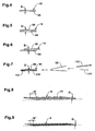
- FIGS. 4 - 7 explains what is meant by a printed product 18 in the present case.
- FIG. 4 schematically shows a printed product 18, which consists of a single printed product 96. This is in the present case a folded printed product 96, of one or more sheets.
- a printed product 18 can be made from two printed products 96, as shown in FIG. 4 shown, these two printed products 96 abut congruent to each other; they may be the same or different printed products 96.
- FIG. 7 shows a possible compilation of a printed product 96, which, if it is held alone by a transport clamp 94, forms a printed product 18.
- the printed product 96 according to FIG. 7 consists of a folded outer part 98 and two inserted therein juxtaposed inner parts, wherein the inner part 100 is also folded and the inner part 100 'is unfolded.
- the outer part 98 and inner part 100 may be, for example, parts of a newspaper and the inner part 100 'to a supplement, such as a card or the like.
- FIG. 8 shows a part of the scale formation S, as it is formed by fed by the conveyor 10 printed products 18 on the infeed conveyor 36.
- the printed matter 18 of the thickness D are arranged at a mutual distance, as indicated by the double arrow S '.
- FIG. 9 also shows a part of a scaly formation S, but now the printed matter 18 compared with FIG. 8 have a smaller thickness D.
- the conveying speed v2 is selected to be smaller in relation to the conveying speed v1, the mutual distance S "of the printed products 18 in comparison to the imbricated formation according to FIG. 8 smaller.
- the inlet belt conveyor 36 forms a processing member 71st
- the device shown in the drawing operates as follows.
- the transport brackets 14 of the conveyor 10 are each equipped with a printed product 18.
- the printed products 18 are moved past the thickness measuring arrangement 24 by means of the conveyor 10.
- Due to the sensor signals of Thickness measuring arrangement 24 determines the signal conditioning unit 26, the measurement signal 28, which corresponds to the thickness of each of the printed products 18 and the control device 30 is supplied. From this measurement signal, the control device 30 also determines the conveying speed v1 of the conveyor device 10. With knowledge of the mutual distance of the transporting clamps 14, the control device 30 can thus also determine the number of printed products 18 produced per unit time.
- the control device 30 depending on the measurement signal 28 and the data determined therefrom, predefines the conveying speed v 2 for the intake belt conveyor 36 and controls the drive motor 40 accordingly.
- the triggering device 20 opens that number of transport clamps 14 moved past it, such as printed matter 16 to be stacked on a stack 70.
- the imbricated formation S is formed, in which each printed product 18 rests on the preceding printed product with the desired spacing S ', S ".
- the control device 30 further determines from the measurement signal 28 the necessary width of the press nip P and controls the servomotor 50 accordingly. In the same way, the control device 30 determines the distance A between the infeed conveyor 36 and the stabilizer 54.
- control device determines the speed with which the corresponding stacking table 68 is to be lowered on the basis of the measurement signal 28 and controls the further drive motor 66 accordingly.
- the waiting position indicated by the upper stacking table 68 can be achieved, for example, by providing a sensor, for example a light barrier, in the area of the infeed conveyor 36 or at its downstream end which sends a signal to the control device 30 when the first printed product 18 arrives ,
- the control device 30 it is also possible for the control device 30 to determine on the basis of the measurement signal 28 when the respectively first printed product 18 of an imbricated formation S is fed to the stacking table 68 and thus has to begin lowering the relevant stacking table 68.
- the respective stacking table 68 is lowered further until the next stacking table 68 is in the waiting position.
- the packaging machine 34 is now ready to take over a further number of supplied printed products 18 and to form a stack 70 therefrom.
- the thickness measuring device 22 is designed for a high measuring speed of, for example, 80000 measurements per hour.
- two or more hornier machines 34 are arranged one behind the other, which are fed by means of the conveyor 10 alternately with printed products 18.
- a packaging machine 34 has been set forth.
- the device according to the invention instead of a packaging machine, has a different processing device 32, from which processing elements can be adjusted or driven depending on the thickness of the printed products 18 to be processed.
- a device for trimming the printed products mentioned in the EP-A-602 594 is disclosed.
- the device according to the invention and the method according to the invention permit, on the one hand, automatic readjustment of the processing device 32 during operation, and, on the other hand, automatic adjustment of the processing device 32 when changing the processing of one type of printed matter 18 to another type of printed matter.
- the thickness of each printed product 18 to be processed by the processor 32 is measured.
- the length of the printed products 18 and scale distances S ', S " can also be entered as fixed parameters to the control device 30. It is also conceivable only a single processing member 71 of the processing device 32 to drive dependent on thickness.
Landscapes
- Engineering & Computer Science (AREA)
- Mechanical Engineering (AREA)
- Separation, Sorting, Adjustment, Or Bending Of Sheets To Be Conveyed (AREA)
- Feeding Of Articles By Means Other Than Belts Or Rollers (AREA)
- Threshing Machine Elements (AREA)
- Projection-Type Copiers In General (AREA)
- General Factory Administration (AREA)
- Inspection Of Paper Currency And Valuable Securities (AREA)
- Discharge By Other Means (AREA)
- Ink Jet (AREA)
Applications Claiming Priority (1)
| Application Number | Priority Date | Filing Date | Title |
|---|---|---|---|
| CH19562004 | 2004-11-26 |
Publications (2)
| Publication Number | Publication Date |
|---|---|
| EP1661833A1 EP1661833A1 (de) | 2006-05-31 |
| EP1661833B1 true EP1661833B1 (de) | 2008-03-05 |
Family
ID=34974222
Family Applications (1)
| Application Number | Title | Priority Date | Filing Date |
|---|---|---|---|
| EP05021602A Expired - Lifetime EP1661833B1 (de) | 2004-11-26 | 2005-10-04 | Verfahren und Vorrichtung zum Verarbeiten von Druckereierzeugnissen |
Country Status (6)
| Country | Link |
|---|---|
| US (1) | US7455171B2 (da) |
| EP (1) | EP1661833B1 (da) |
| AT (1) | ATE388109T1 (da) |
| DE (1) | DE502005003078D1 (da) |
| DK (1) | DK1661833T3 (da) |
| ES (1) | ES2300917T3 (da) |
Families Citing this family (5)
| Publication number | Priority date | Publication date | Assignee | Title |
|---|---|---|---|---|
| DK1854751T3 (da) * | 2006-05-10 | 2013-05-21 | Ferag Ag | Indretning til kontrol af flade produkter, som holdes samlet i en klemme |
| JP2010524065A (ja) | 2007-04-03 | 2010-07-15 | フェラーク・アクチェンゲゼルシャフト | 平坦物を計数及び検知するための装置並びに方法 |
| JP5551981B2 (ja) * | 2009-07-28 | 2014-07-16 | 株式会社イシダ | 箱詰装置 |
| US8857806B2 (en) | 2010-04-21 | 2014-10-14 | Muller Martini Corp. | Apparatus and method for orienting products for applying indicia during transport |
| CH703919A1 (de) * | 2010-10-13 | 2012-04-13 | Ferag Ag | Verfahren zum Betrieb einer Transportvorrichtung sowie Transportvorrichtung zur Durchführung des Verfahrens. |
Family Cites Families (15)
| Publication number | Priority date | Publication date | Assignee | Title |
|---|---|---|---|---|
| US3507492A (en) * | 1967-10-06 | 1970-04-21 | Bonnierfoeretagen Ab | Stacking machine with flow control system |
| US4037525A (en) * | 1975-07-30 | 1977-07-26 | Eds, Inc. | Signature stacker employing swingable intercept means driven in a non-linear fashion |
| CH660171A5 (de) * | 1983-06-09 | 1987-03-31 | Ferag Ag | Verfahren und vorrichtung zum zwischenspeichern von in einem schuppenstrom anfallenden druckprodukten, wie zeitungen, zeitschriften oder dgl. |
| CH660350A5 (de) * | 1983-06-14 | 1987-04-15 | Ferag Ag | Einrichtung zum feststellen mehrfach belegter plaetze in einem kontinuierlich gefoerderten strom von gleichmaessige abstaende voneinander aufweisenden druckprodukten sowie verwendung dieser einrichtung. |
| DE3814401C1 (da) * | 1988-04-28 | 1989-06-01 | Man Roland Druckmaschinen Ag, 6050 Offenbach, De | |
| US5477240A (en) * | 1990-04-11 | 1995-12-19 | Q-Co Industries, Inc. | Character scrolling method and apparatus |
| DE59104989D1 (de) | 1990-10-05 | 1995-04-27 | Ferag Ag | Dickenmessung an Druckprodukten in einem Schuppenstrom. |
| DE59306510D1 (de) * | 1992-12-02 | 1997-06-26 | Ferag Ag | Greifer für eine Fördereinrichtung zum Fördern von ein- oder mehrblättrigen Druckereierzeugnissen |
| DE4243060C2 (de) | 1992-12-18 | 1994-09-15 | Ferag Ag | Einrichtung zum Beschneiden von flächigen Erzeugnissen, insbesondere mehrblättrigen Druckerzeugnissen |
| US5772391A (en) * | 1995-11-22 | 1998-06-30 | Quipp Systems, Inc. | Stacker for counting and stacking signatures delivered by a gripper conveyor |
| ES2176869T3 (es) * | 1997-08-15 | 2002-12-01 | Ferag Ag | Procedimiento y dispositivo para controlar el espesor de objetos planos transportados de modo continuo. |
| US6543989B1 (en) * | 1999-07-06 | 2003-04-08 | Kraft Foods Holdings, Inc. | Lowering arms stacking apparatus |
| EP1148007B1 (de) * | 2000-04-19 | 2003-07-30 | Grapha-Holding AG | Vorrichtung zur Entnahme von auf einer Fördervorrichtung in regelmässigen Abständen transportierten Druckprodukten |
| US6876716B2 (en) * | 2003-02-19 | 2005-04-05 | Quipp Systems, Inc. | Method and apparatus for utilizing a shadow effect for counting newspapers, magazines, books, printed products, signatures and other like printed matter |
| US7002135B2 (en) * | 2003-08-20 | 2006-02-21 | Quipp Systems, Inc. | Method and apparatus for precision counting and tracking of signatures moving between a gripper conveyor and a stacker infeed |
-
2005
- 2005-10-04 DK DK05021602T patent/DK1661833T3/da active
- 2005-10-04 ES ES05021602T patent/ES2300917T3/es not_active Expired - Lifetime
- 2005-10-04 DE DE502005003078T patent/DE502005003078D1/de not_active Expired - Lifetime
- 2005-10-04 AT AT05021602T patent/ATE388109T1/de active
- 2005-10-04 EP EP05021602A patent/EP1661833B1/de not_active Expired - Lifetime
- 2005-11-28 US US11/287,997 patent/US7455171B2/en not_active Expired - Fee Related
Also Published As
| Publication number | Publication date |
|---|---|
| ES2300917T3 (es) | 2008-06-16 |
| EP1661833A1 (de) | 2006-05-31 |
| US20060113165A1 (en) | 2006-06-01 |
| US7455171B2 (en) | 2008-11-25 |
| DK1661833T3 (da) | 2008-06-09 |
| ATE388109T1 (de) | 2008-03-15 |
| DE502005003078D1 (de) | 2008-04-17 |
Similar Documents
| Publication | Publication Date | Title |
|---|---|---|
| EP2447197B1 (de) | Vorrichtung und Verfahren zum Wenden von Stapeln aus bogenförmigem Material | |
| AT400327B (de) | Vorrichtung zum beschicken einer vereinzelungseinrichtung für druckprodukte | |
| CH689773A5 (de) | Vorrichtung zum Vergleichmaessigen des Abstandes zwischen aufeinanderfolgenden flaechigen Produkten. | |
| DE1761688B2 (de) | Transporteinrichtung für in einer Schuppenformation anfallende, flächenhafte Gebilde | |
| DE3844897C2 (de) | Verzögerungs-Vorrichtung für Bogenlagen | |
| EP2883820B1 (de) | Vorrichtung und Verfahren zum Eintakten von Buchblocks | |
| EP1832399B1 (de) | Verfahren und Vorrichtung zum selbsttätigen Beschneiden von Druckerzeugnissen | |
| EP0625122B1 (de) | Einrichtung zum fördern und trennen von gefalteten druckprodukten | |
| EP2133212B1 (de) | Einrichtung zur Bearbeitung eines in einer umlaufenden Klammer einer Buchbindemaschine aus der Klammer hängend vorstehenden Rückens eines Buchblocks | |
| EP3533609B1 (de) | Vorrichtung und verfahren zur weiterverarbeitung sequenziell bedruckter druckbogen | |
| EP1661833B1 (de) | Verfahren und Vorrichtung zum Verarbeiten von Druckereierzeugnissen | |
| EP0478911A1 (de) | Vorrichtung zum wahlweisen Überführen von Erzeugnissen aus einer entlang eines ersten Förderweges transportierten Schuppenformation auf einen zweiten Förderweg | |
| DE602004004447T2 (de) | Vorrichtung zum Umwickeln von gruppierten Gegenständen | |
| EP2935060B1 (de) | Vorrichtung und verfahren zum drehen von flachen gütern | |
| EP2055660B1 (de) | Vorrichtung zum getakteten Umlenken von flächigen Gegenständen | |
| EP0254851B1 (de) | Vorrichtung zum Vergleichmässigen des Abstandes zwischen aufeinanderfolgenden Produkten einer Schuppenformation | |
| EP2138439B1 (de) | Vorrichtung zum Stapeln von flächigen Produkten, insbesondere Druckereiprodukten | |
| EP3059195B1 (de) | Falzvorrichtung und Verfahren | |
| CH694504A5 (de) | Verfahren zum Schneiden von Blechtafeln zu Blechstreifen sowie Schneidevorrichtung zu dessen Durchfuehrung. | |
| EP2275373A1 (de) | Verfahren und Vorrichtung zum kontinuierlichen Zusammenführen von zumindest zwei Schuppenströmen flächiger Druckprodukte | |
| EP2746204B1 (de) | Vorrichtung und Verfahren zum Drehen von flachen Gütern | |
| EP1059256B9 (de) | Vorrichtung zum Korrigieren der Lage von geschuppt anfallenden flächigen Gegenständen | |
| EP2316767B1 (de) | Verfahren und Vorrichtung zum Herstellen von Stapeln aus Druckprodukten | |
| DE19743020C2 (de) | Vorrichtung sowie Verfahren zur Vereinzelung von Druckprodukten | |
| CH657349A5 (de) | Verfahren und einrichtung zur korrektur, beziehungsweise verhinderung des vorwaerts- oder rueckwaerts-ueberhanges eines aus einer papierbahn in zick-zack gefalteten stapels von endlosformularen. |
Legal Events
| Date | Code | Title | Description |
|---|---|---|---|
| PUAI | Public reference made under article 153(3) epc to a published international application that has entered the european phase |
Free format text: ORIGINAL CODE: 0009012 |
|
| AK | Designated contracting states |
Kind code of ref document: A1 Designated state(s): AT BE BG CH CY CZ DE DK EE ES FI FR GB GR HU IE IS IT LI LT LU LV MC NL PL PT RO SE SI SK TR |
|
| AX | Request for extension of the european patent |
Extension state: AL BA HR MK YU |
|
| 17P | Request for examination filed |
Effective date: 20060627 |
|
| R17C | First examination report despatched (corrected) |
Effective date: 20060803 |
|
| AKX | Designation fees paid |
Designated state(s): AT BE BG CH CY CZ DE DK EE ES FI FR GB GR HU IE IS IT LI LT LU LV MC NL PL PT RO SE SI SK TR |
|
| GRAP | Despatch of communication of intention to grant a patent |
Free format text: ORIGINAL CODE: EPIDOSNIGR1 |
|
| GRAS | Grant fee paid |
Free format text: ORIGINAL CODE: EPIDOSNIGR3 |
|
| GRAA | (expected) grant |
Free format text: ORIGINAL CODE: 0009210 |
|
| AK | Designated contracting states |
Kind code of ref document: B1 Designated state(s): AT BE BG CH CY CZ DE DK EE ES FI FR GB GR HU IE IS IT LI LT LU LV MC NL PL PT RO SE SI SK TR |
|
| REG | Reference to a national code |
Ref country code: GB Ref legal event code: FG4D Free format text: NOT ENGLISH |
|
| REG | Reference to a national code |
Ref country code: CH Ref legal event code: EP |
|
| GBT | Gb: translation of ep patent filed (gb section 77(6)(a)/1977) |
Effective date: 20080313 |
|
| REG | Reference to a national code |
Ref country code: IE Ref legal event code: FG4D Free format text: LANGUAGE OF EP DOCUMENT: GERMAN |
|
| REF | Corresponds to: |
Ref document number: 502005003078 Country of ref document: DE Date of ref document: 20080417 Kind code of ref document: P |
|
| REG | Reference to a national code |
Ref country code: CH Ref legal event code: NV Representative=s name: PATENTANWAELTE SCHAAD, BALASS, MENZL & PARTNER AG |
|
| REG | Reference to a national code |
Ref country code: DK Ref legal event code: T3 |
|
| REG | Reference to a national code |
Ref country code: SE Ref legal event code: TRGR |
|
| REG | Reference to a national code |
Ref country code: ES Ref legal event code: FG2A Ref document number: 2300917 Country of ref document: ES Kind code of ref document: T3 |
|
| PG25 | Lapsed in a contracting state [announced via postgrant information from national office to epo] |
Ref country code: FI Free format text: LAPSE BECAUSE OF FAILURE TO SUBMIT A TRANSLATION OF THE DESCRIPTION OR TO PAY THE FEE WITHIN THE PRESCRIBED TIME-LIMIT Effective date: 20080305 |
|
| NLV1 | Nl: lapsed or annulled due to failure to fulfill the requirements of art. 29p and 29m of the patents act | ||
| PG25 | Lapsed in a contracting state [announced via postgrant information from national office to epo] |
Ref country code: PL Free format text: LAPSE BECAUSE OF FAILURE TO SUBMIT A TRANSLATION OF THE DESCRIPTION OR TO PAY THE FEE WITHIN THE PRESCRIBED TIME-LIMIT Effective date: 20080305 Ref country code: SI Free format text: LAPSE BECAUSE OF FAILURE TO SUBMIT A TRANSLATION OF THE DESCRIPTION OR TO PAY THE FEE WITHIN THE PRESCRIBED TIME-LIMIT Effective date: 20080305 Ref country code: LV Free format text: LAPSE BECAUSE OF FAILURE TO SUBMIT A TRANSLATION OF THE DESCRIPTION OR TO PAY THE FEE WITHIN THE PRESCRIBED TIME-LIMIT Effective date: 20080305 |
|
| REG | Reference to a national code |
Ref country code: IE Ref legal event code: FD4D |
|
| PG25 | Lapsed in a contracting state [announced via postgrant information from national office to epo] |
Ref country code: PT Free format text: LAPSE BECAUSE OF FAILURE TO SUBMIT A TRANSLATION OF THE DESCRIPTION OR TO PAY THE FEE WITHIN THE PRESCRIBED TIME-LIMIT Effective date: 20080805 Ref country code: SK Free format text: LAPSE BECAUSE OF FAILURE TO SUBMIT A TRANSLATION OF THE DESCRIPTION OR TO PAY THE FEE WITHIN THE PRESCRIBED TIME-LIMIT Effective date: 20080305 Ref country code: CZ Free format text: LAPSE BECAUSE OF FAILURE TO SUBMIT A TRANSLATION OF THE DESCRIPTION OR TO PAY THE FEE WITHIN THE PRESCRIBED TIME-LIMIT Effective date: 20080305 Ref country code: NL Free format text: LAPSE BECAUSE OF FAILURE TO SUBMIT A TRANSLATION OF THE DESCRIPTION OR TO PAY THE FEE WITHIN THE PRESCRIBED TIME-LIMIT Effective date: 20080305 |
|
| PG25 | Lapsed in a contracting state [announced via postgrant information from national office to epo] |
Ref country code: RO Free format text: LAPSE BECAUSE OF FAILURE TO SUBMIT A TRANSLATION OF THE DESCRIPTION OR TO PAY THE FEE WITHIN THE PRESCRIBED TIME-LIMIT Effective date: 20080305 |
|
| EN | Fr: translation not filed | ||
| PG25 | Lapsed in a contracting state [announced via postgrant information from national office to epo] |
Ref country code: IS Free format text: LAPSE BECAUSE OF FAILURE TO SUBMIT A TRANSLATION OF THE DESCRIPTION OR TO PAY THE FEE WITHIN THE PRESCRIBED TIME-LIMIT Effective date: 20080705 |
|
| PLBE | No opposition filed within time limit |
Free format text: ORIGINAL CODE: 0009261 |
|
| STAA | Information on the status of an ep patent application or granted ep patent |
Free format text: STATUS: NO OPPOSITION FILED WITHIN TIME LIMIT |
|
| PG25 | Lapsed in a contracting state [announced via postgrant information from national office to epo] |
Ref country code: LT Free format text: LAPSE BECAUSE OF FAILURE TO SUBMIT A TRANSLATION OF THE DESCRIPTION OR TO PAY THE FEE WITHIN THE PRESCRIBED TIME-LIMIT Effective date: 20080305 Ref country code: IE Free format text: LAPSE BECAUSE OF FAILURE TO SUBMIT A TRANSLATION OF THE DESCRIPTION OR TO PAY THE FEE WITHIN THE PRESCRIBED TIME-LIMIT Effective date: 20080305 |
|
| 26N | No opposition filed |
Effective date: 20081208 |
|
| BERE | Be: lapsed |
Owner name: FERAG AG Effective date: 20081031 |
|
| PG25 | Lapsed in a contracting state [announced via postgrant information from national office to epo] |
Ref country code: BG Free format text: LAPSE BECAUSE OF FAILURE TO SUBMIT A TRANSLATION OF THE DESCRIPTION OR TO PAY THE FEE WITHIN THE PRESCRIBED TIME-LIMIT Effective date: 20080605 Ref country code: FR Free format text: LAPSE BECAUSE OF FAILURE TO SUBMIT A TRANSLATION OF THE DESCRIPTION OR TO PAY THE FEE WITHIN THE PRESCRIBED TIME-LIMIT Effective date: 20081226 Ref country code: EE Free format text: LAPSE BECAUSE OF FAILURE TO SUBMIT A TRANSLATION OF THE DESCRIPTION OR TO PAY THE FEE WITHIN THE PRESCRIBED TIME-LIMIT Effective date: 20080305 |
|
| PG25 | Lapsed in a contracting state [announced via postgrant information from national office to epo] |
Ref country code: MC Free format text: LAPSE BECAUSE OF NON-PAYMENT OF DUE FEES Effective date: 20081031 |
|
| PG25 | Lapsed in a contracting state [announced via postgrant information from national office to epo] |
Ref country code: CY Free format text: LAPSE BECAUSE OF FAILURE TO SUBMIT A TRANSLATION OF THE DESCRIPTION OR TO PAY THE FEE WITHIN THE PRESCRIBED TIME-LIMIT Effective date: 20080305 Ref country code: BE Free format text: LAPSE BECAUSE OF NON-PAYMENT OF DUE FEES Effective date: 20081031 |
|
| PG25 | Lapsed in a contracting state [announced via postgrant information from national office to epo] |
Ref country code: HU Free format text: LAPSE BECAUSE OF FAILURE TO SUBMIT A TRANSLATION OF THE DESCRIPTION OR TO PAY THE FEE WITHIN THE PRESCRIBED TIME-LIMIT Effective date: 20080906 Ref country code: LU Free format text: LAPSE BECAUSE OF NON-PAYMENT OF DUE FEES Effective date: 20081004 |
|
| PG25 | Lapsed in a contracting state [announced via postgrant information from national office to epo] |
Ref country code: TR Free format text: LAPSE BECAUSE OF FAILURE TO SUBMIT A TRANSLATION OF THE DESCRIPTION OR TO PAY THE FEE WITHIN THE PRESCRIBED TIME-LIMIT Effective date: 20080305 |
|
| PG25 | Lapsed in a contracting state [announced via postgrant information from national office to epo] |
Ref country code: GR Free format text: LAPSE BECAUSE OF FAILURE TO SUBMIT A TRANSLATION OF THE DESCRIPTION OR TO PAY THE FEE WITHIN THE PRESCRIBED TIME-LIMIT Effective date: 20080606 |
|
| PGFP | Annual fee paid to national office [announced via postgrant information from national office to epo] |
Ref country code: ES Payment date: 20121026 Year of fee payment: 8 |
|
| REG | Reference to a national code |
Ref country code: ES Ref legal event code: FD2A Effective date: 20150709 |
|
| PG25 | Lapsed in a contracting state [announced via postgrant information from national office to epo] |
Ref country code: ES Free format text: LAPSE BECAUSE OF NON-PAYMENT OF DUE FEES Effective date: 20131005 |
|
| PGFP | Annual fee paid to national office [announced via postgrant information from national office to epo] |
Ref country code: DK Payment date: 20151021 Year of fee payment: 11 |
|
| PGFP | Annual fee paid to national office [announced via postgrant information from national office to epo] |
Ref country code: IT Payment date: 20151028 Year of fee payment: 11 |
|
| PGFP | Annual fee paid to national office [announced via postgrant information from national office to epo] |
Ref country code: SE Payment date: 20151021 Year of fee payment: 11 Ref country code: AT Payment date: 20151022 Year of fee payment: 11 |
|
| PGFP | Annual fee paid to national office [announced via postgrant information from national office to epo] |
Ref country code: GB Payment date: 20161020 Year of fee payment: 12 |
|
| REG | Reference to a national code |
Ref country code: DK Ref legal event code: EBP Effective date: 20161031 |
|
| REG | Reference to a national code |
Ref country code: AT Ref legal event code: MM01 Ref document number: 388109 Country of ref document: AT Kind code of ref document: T Effective date: 20161004 |
|
| REG | Reference to a national code |
Ref country code: DE Ref legal event code: R082 Ref document number: 502005003078 Country of ref document: DE Representative=s name: KLUNKER IP PATENTANWAELTE PARTG MBB, DE |
|
| PG25 | Lapsed in a contracting state [announced via postgrant information from national office to epo] |
Ref country code: SE Free format text: LAPSE BECAUSE OF NON-PAYMENT OF DUE FEES Effective date: 20161005 Ref country code: AT Free format text: LAPSE BECAUSE OF NON-PAYMENT OF DUE FEES Effective date: 20161004 |
|
| PG25 | Lapsed in a contracting state [announced via postgrant information from national office to epo] |
Ref country code: IT Free format text: LAPSE BECAUSE OF NON-PAYMENT OF DUE FEES Effective date: 20161004 |
|
| PG25 | Lapsed in a contracting state [announced via postgrant information from national office to epo] |
Ref country code: DK Free format text: LAPSE BECAUSE OF NON-PAYMENT OF DUE FEES Effective date: 20161031 |
|
| GBPC | Gb: european patent ceased through non-payment of renewal fee |
Effective date: 20171004 |
|
| PG25 | Lapsed in a contracting state [announced via postgrant information from national office to epo] |
Ref country code: GB Free format text: LAPSE BECAUSE OF NON-PAYMENT OF DUE FEES Effective date: 20171004 |
|
| PGFP | Annual fee paid to national office [announced via postgrant information from national office to epo] |
Ref country code: DE Payment date: 20181019 Year of fee payment: 14 |
|
| PGFP | Annual fee paid to national office [announced via postgrant information from national office to epo] |
Ref country code: CH Payment date: 20181224 Year of fee payment: 14 |
|
| REG | Reference to a national code |
Ref country code: DE Ref legal event code: R119 Ref document number: 502005003078 Country of ref document: DE |
|
| REG | Reference to a national code |
Ref country code: CH Ref legal event code: PL |
|
| PG25 | Lapsed in a contracting state [announced via postgrant information from national office to epo] |
Ref country code: LI Free format text: LAPSE BECAUSE OF NON-PAYMENT OF DUE FEES Effective date: 20191031 Ref country code: DE Free format text: LAPSE BECAUSE OF NON-PAYMENT OF DUE FEES Effective date: 20200501 Ref country code: CH Free format text: LAPSE BECAUSE OF NON-PAYMENT OF DUE FEES Effective date: 20191031 |