EP1661709B1 - Drucker - Google Patents
Drucker Download PDFInfo
- Publication number
- EP1661709B1 EP1661709B1 EP05110199A EP05110199A EP1661709B1 EP 1661709 B1 EP1661709 B1 EP 1661709B1 EP 05110199 A EP05110199 A EP 05110199A EP 05110199 A EP05110199 A EP 05110199A EP 1661709 B1 EP1661709 B1 EP 1661709B1
- Authority
- EP
- European Patent Office
- Prior art keywords
- contact point
- printer
- unit
- contact
- sections
- Prior art date
- Legal status (The legal status is an assumption and is not a legal conclusion. Google has not performed a legal analysis and makes no representation as to the accuracy of the status listed.)
- Expired - Lifetime
Links
Images


Classifications
-
- B—PERFORMING OPERATIONS; TRANSPORTING
- B41—PRINTING; LINING MACHINES; TYPEWRITERS; STAMPS
- B41J—TYPEWRITERS; SELECTIVE PRINTING MECHANISMS, i.e. MECHANISMS PRINTING OTHERWISE THAN FROM A FORME; CORRECTION OF TYPOGRAPHICAL ERRORS
- B41J2/00—Typewriters or selective printing mechanisms characterised by the printing or marking process for which they are designed
- B41J2/005—Typewriters or selective printing mechanisms characterised by the printing or marking process for which they are designed characterised by bringing liquid or particles selectively into contact with a printing material
- B41J2/01—Ink jet
- B41J2/17—Ink jet characterised by ink handling
- B41J2/175—Ink supply systems ; Circuit parts therefor
- B41J2/17503—Ink cartridges
- B41J2/17526—Electrical contacts to the cartridge
-
- B—PERFORMING OPERATIONS; TRANSPORTING
- B41—PRINTING; LINING MACHINES; TYPEWRITERS; STAMPS
- B41J—TYPEWRITERS; SELECTIVE PRINTING MECHANISMS, i.e. MECHANISMS PRINTING OTHERWISE THAN FROM A FORME; CORRECTION OF TYPOGRAPHICAL ERRORS
- B41J2/00—Typewriters or selective printing mechanisms characterised by the printing or marking process for which they are designed
- B41J2/005—Typewriters or selective printing mechanisms characterised by the printing or marking process for which they are designed characterised by bringing liquid or particles selectively into contact with a printing material
- B41J2/01—Ink jet
- B41J2/135—Nozzles
- B41J2/145—Arrangement thereof
- B41J2/155—Arrangement thereof for line printing
Definitions
- the present invention relates to printers, particularly but not exclusively to an inkjet printer having a contact structure on a print head that is substantially as wide as a sheet of paper.
- an inkjet printer forms an image on a sheet of paper by ejecting droplets of ink onto the paper from a print head suspended over the surface of the paper.
- the print head shuttles perpendicularly to the paper's transport direction, and, thus, conventional inkjet printers are occasionally referred to as shuttle type printers.
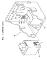
- Figure 1 is an exploded perspective view of an ink cartridge 10 and a carrier 20 of a conventional shuttle type printer.
- the ink cartridge 10 is loaded into the carrier 20 and, under the control of electrical signals received via an electrical connection to the carrier 20, a nozzle unit provided on the ink cartridge 10 ejects ink onto the sheet of paper.
- electrical contact between the ink cartridge 10 and the carrier 20 is achieved by a contact arrangement including a plurality of contact points 12 formed on the ink cartridge 10 and a plurality of contact points 22 formed on a flexible printed circuit board (PCB) 26 connected to the carrier 20. Electrical contact between corresponding contact points 12, 22 of the ink cartridge 10 and carrier 20 is achieved when the ink cartridge 10 is loaded into the carrier 20.
- a contact arrangement including a plurality of contact points 12 formed on the ink cartridge 10 and a plurality of contact points 22 formed on a flexible printed circuit board (PCB) 26 connected to the carrier 20.
- PCB printed circuit board
- the carrier 20 includes on its inner surface a control PCB 24 on which control circuitry is located for receiving and transmitting control signals to and from an external device such as a computer and for providing control signals to the nozzle unit.
- the control PCB 24 is electrically connected to one end of the flexible PCB 26.
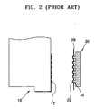
- the contact points 22 of the flexible PCB 26 are required to protrude to contact the contact points 12 of the ink cartridge 10 when the ink cartridge 10 is loaded into the carrier 20.
- an elastic rubber member 30 is installed beneath the flexible PCB 26.
- the rubber member 30 has a plurality of protrusions 32 that press against the flexible PCB 26 and correspond to the protruding contact points 22 of the flexible PCB 26.
- This printer includes a nozzle unit substantially as wide as a sheet of paper.
- the nozzle unit prints consecutive lines of dots of ink on the printing paper as the paper moves past the nozzle unit.
- Such printers are also referred to herein as fixed head printers since the head does not shuttle across the printing paper as with shuttle-type printers.
- the print heads of such printers are referred to herein as full-width print heads.
- a contact device formed from a single member and having contacts similar to those formed on the flexible PCB 26 of the carrier 20 of the above described shuttle type printer can be provided on fixed head printers to establish electrical contact between the nozzle unit and the control circuitry of the printer. Since the nozzle unit of fixed-head printers is as wide as the sheet of paper to be printed on, the contact device may also be required to be as wide as the sheet of paper.
- a greater force may be applied between the contact device and the nozzle unit to ensure that the nozzle unit contacts the contact device along the length of the contact device. The greater force may, however, break the nozzle unit or contact device.
- the present invention aims to address these problems.
- EP 0652107 A2 describes a parallel thermal ink jet printing device produced by assembling a plurality of modules.
- an inkjet printer includes a print head having a width corresponding to a width of a sheet of paper.
- the printer has a plurality of nozzle sections and a plurality of contact devices corresponding to the nozzle sections.
- the contact devices preferably operate independently of one another.
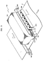
- an inkjet printer 100 includes a print head 110, a plurality of contact devices 200, and a transport roller 130.
- the print head 110 has a width corresponding to a width of a sheet of paper P.
- the print head 110 includes a nozzle unit 111 including a plurality of nozzle sections 112 in a lower part thereof.
- a contact point unit 120 is electrically connected to the nozzle sections 112 and includes a plurality of nodes 121.
- the contact devices 200 contact the nodes 121 of the contact point unit 120 to form an electrical connection and transmit an electrical signal corresponding to an image signal to the nodes 121 of the contact point unit 120.
- the contact devices 200 include a printed circuit board (PCB) 210 and an elastic member 220.
- the PCB 210 receives an electrical signal corresponding to an image signal and includes a plurality of contact point sections 211.
- the contact point sections 211 are formed by cutting slots in the PCB 210 that extend a predetermined length 1 from an edge of the PCB 210. In the present example, the slots extend in a direction perpendicular to the sheet of paper P.
- the contact point sections 211 include a plurality of protruding nodes 212. Since the contact point sections 211 are separated from one another by the slots, they can operate independently without interfering with one another.
- the predetermined length 1 of the slots can be sufficient to allow each of the neighbouring contact sections 211 to operate, or move, without interfering with operations of the other neighboring contact point sections 211.
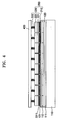
- the elastic members 220 press the contact point sections 211 towards the contact point unit 120 to make an electrical connection.
- Each of the elastic members 220 includes a pressing unit 221, a supporting unit 222, and a spring unit 223.
- the pressing units 221 are attached to the supporting units 222, and each of the pressing units 221 includes a plurality of protrusions 2211 corresponding to the nodes 212 of the contact point sections 211.
- the protrusions 2211 press the nodes 212 of the PCB 210 into contact with the nodes 121 of the contact point unit 120.
- the protrusions 2211 may be formed of an elastic material such that they can easily contact the nodes 121 of the contact point unit 120.
- the shapes of the nodes 212 of the contact point sections 211 and those of the protrusions 2211 are not limited in the present invention, but have any of a variety of shapes that serves their function.
- the supporting units 222 are interposed between the pressing units 221 and the spring units 223, and deliver the biasing force provided by the spring units 223 to the pressing units 221 as a result of their connection with the spring units 223.
- the spring units 223 are connected to a body frame 400 and press the supporting units 222 and the pressing units 221 towards the contact point unit 120 of the print head 110 in a direction away from the body frame 400.
- the elastic members 220 correspond to the contact point sections 221 such that the force of each spring unit 223 acts on a separate one of the contact point sections 221. Therefore, independent contact loads can be imposed on the contact point sections 221, and thus the contact point sections 221 are not affected by one another.
- the contact point sections 221 can contact the contact point unit 120 due to the independent contact loads on the contact point sections 221.
- the transport roller 130 conveys the sheet of paper P to the print head 110 such that an image can be formed on the sheet of paper P by the nozzle unit 111.
- an inkjet printer includes a plurality of contact devices contacting a plurality of contact point units of a print head.
- the contact devices can operate independently, ensuring reliable electrical connections.
Landscapes
- Ink Jet (AREA)
- Accessory Devices And Overall Control Thereof (AREA)
- Particle Formation And Scattering Control In Inkjet Printers (AREA)
Claims (9)
- Drucker (100) umfassend:einen Druckerkopf (110) zum Drucken auf ein Blatt Papier, wobei der Druckerkopf (110) eine Breite aufweist, die im Wesentlichen der Breite des Blatts Papier entspricht und eine Mehrzahl von Düsenabschnitten (112) und eine Kontaktstelleneinheit (120), die elektrisch an die Düsenabschnitte (112) angeschlossen ist;eine gedruckte Schaltung (210), die eine Mehrzahl von Kontaktstellenabschnitten (211) umfasst, wobei jeder Kontaktstellenabschnitt (211) einem der Mehrzahl von Düsenabschnitten (112) entspricht und von den anderen Kontaktstellenabschnitten (211) unabhängig bewegbar ist; undeine Mehrzahl elastischer Teile (223), von denen jeder so angeordnet ist, dass er eine beeinflussende Kraft zwischen einem jeweiligen Kontaktstellenabschnitt (211) und der Kontaktstelleneinheit (120) des Druckerkopfs (110) bereitstellt, um zu ermöglichen, dass ein elektrischer Anschluss zwischen dem Kontaktstellenabschnitt (211) und der Kontaktstelleneinheit (120) gebildet wird.
- Drucker (100) nach Anspruch 1, wobei jeder Kontaktstellenabschnitt (211) eine Mehrzahl von Verzweigungspunkten (212) zum Kontaktieren der Kontaktstelleneinheit (120) aufweist.
- Drucker (100) nach Anspruch 2, wobei die Kontaktstellenabschnitte (211) durch Schlitze in der gedruckten Schaltung (210) von einander getrennt sind.
- Drucker (100) nach Anspruch 3, wobei jeder Schlitz sich von einer Kante der gedruckten Schaltung (210) aus erstreckt.
- Drucker (100) nach Anspruch 4, wobei jeder Schlitz sich über eine Entfernung erstreckt, die es jedem ihrer benachbarten Kontaktstellenabschnitte (211) erlaubt, sich unabhängig zu bewegen.
- Drucker (100) nach einem der vorhergehenden Ansprüche, wobei jeder elastische Teil (223) Folgendes umfasst:eine Drückeinheit (221), die installiert ist, um einen der Kontaktstellenabschnitte (211) zu kontaktieren; undeine Trägereinheit (222), die die Drückeinheit (221) trägt, wobei jeder der elastischen Teile (223) eine Federeinheit (223) zum Drücken einer jeweiligen Trägereinheit (222) auf eine Drückeinheit (221) zu umfasst.
- Drucker (100) nach Anspruch 6, des Weiteren umfassend einen Körperrahmen (400) und wobei die Federeinheit (223) durch den Körperrahmen (400) getragen wird und eine Druckfeder ist.
- Drucker (100) nach einem der vorhergehenden Ansprüche, wobei
die elastischen Teile (223) von einander getrennt sind, um nicht störend auf einander einzuwirken. - Drucker (100) nach einem der vorhergehenden Ansprüche, wobei der Druckerkopf ein Tintenstrahldruckerkopf ist.
Applications Claiming Priority (1)
| Application Number | Priority Date | Filing Date | Title |
|---|---|---|---|
| KR1020040098357A KR100584611B1 (ko) | 2004-11-27 | 2004-11-27 | 잉크젯 프린터 |
Publications (2)
| Publication Number | Publication Date |
|---|---|
| EP1661709A1 EP1661709A1 (de) | 2006-05-31 |
| EP1661709B1 true EP1661709B1 (de) | 2010-03-10 |
Family
ID=35957772
Family Applications (1)
| Application Number | Title | Priority Date | Filing Date |
|---|---|---|---|
| EP05110199A Expired - Lifetime EP1661709B1 (de) | 2004-11-27 | 2005-10-31 | Drucker |
Country Status (5)
| Country | Link |
|---|---|
| US (1) | US20060114290A1 (de) |
| EP (1) | EP1661709B1 (de) |
| KR (1) | KR100584611B1 (de) |
| CN (1) | CN1778558A (de) |
| DE (1) | DE602005019832D1 (de) |
Family Cites Families (20)
| Publication number | Priority date | Publication date | Assignee | Title |
|---|---|---|---|---|
| US5461482A (en) * | 1993-04-30 | 1995-10-24 | Hewlett-Packard Company | Electrical interconnect system for a printer |
| DE69319092T2 (de) * | 1993-04-30 | 1999-01-07 | Hewlett-Packard Co., Palo Alto, Calif. | Modularer Wagenzusammenbau für einen Tintenstrahldrucker |
| JPH0781049A (ja) * | 1993-09-16 | 1995-03-28 | Canon Inc | インクジェット記録装置および該装置を備えた情報処理システム |
| IT1272050B (it) * | 1993-11-10 | 1997-06-11 | Olivetti Canon Ind Spa | Dispositivo stampante parallelo con struttura modulare e relativo procedimento di realizzazione. |
| US5835111A (en) * | 1995-10-31 | 1998-11-10 | Hewlett-Packard Company | Compact flex-circuit interconnect for inkjet printheads |
| KR0164537B1 (ko) * | 1995-11-27 | 1999-03-30 | 김광호 | 잉크젯 프린트기기에 있어서 헤드의 파워 연결 단자부 청소장치 |
| US5923353A (en) * | 1996-09-23 | 1999-07-13 | Hewlett-Packard Company | Fail-safe, backup valve in a pressurized ink delivery apparatus |
| US6224192B1 (en) * | 1998-10-06 | 2001-05-01 | Hewlett-Packard Company | Inkjet printing systems using a modular print cartridge assembly |
| US6280017B1 (en) * | 1998-10-27 | 2001-08-28 | Canon Kabushiki Kaisha | Recording apparatus |
| GB9925637D0 (en) * | 1999-10-29 | 1999-12-29 | Neopost Ltd | Housing for digital print head |
| JP4557386B2 (ja) * | 2000-07-10 | 2010-10-06 | キヤノン株式会社 | 記録ヘッド用基板の製造方法 |
| KR100406943B1 (ko) * | 2000-10-28 | 2003-11-21 | 삼성전자주식회사 | 프린트 어레이 헤드 및 그 제조방법 |
| JP3649123B2 (ja) * | 2000-12-26 | 2005-05-18 | セイコーエプソン株式会社 | 回路基板の端子 |
| KR100385987B1 (ko) * | 2001-01-22 | 2003-06-02 | 삼성전자주식회사 | 잉크젯 프린터의 전기적 접점장치 |
| US6394580B1 (en) * | 2001-03-20 | 2002-05-28 | Hewlett-Packard Company | Electrical interconnection for wide-array inkjet printhead assembly |
| US6776475B2 (en) * | 2002-10-25 | 2004-08-17 | Hewlett-Packard Development Company, L.P. | Interconnect system and method for inkjet devices using conductive elastomer |
| US6736488B1 (en) * | 2003-05-23 | 2004-05-18 | Hewlett-Packard Development Company, L.P. | Electrical interconnect for printhead assembly |
| KR100828355B1 (ko) * | 2004-05-25 | 2008-05-08 | 삼성전자주식회사 | 잉크젯 프린터 |
| KR100571965B1 (ko) * | 2004-09-25 | 2006-04-17 | 삼성전자주식회사 | 잉크젯 프린팅 헤드 및 이를 채용한 잉크젯 프린터 |
| JP2006088629A (ja) * | 2004-09-27 | 2006-04-06 | Brother Ind Ltd | インクジェットヘッド |
-
2004
- 2004-11-27 KR KR1020040098357A patent/KR100584611B1/ko not_active Expired - Fee Related
-
2005
- 2005-09-27 US US11/235,072 patent/US20060114290A1/en not_active Abandoned
- 2005-10-28 CN CNA2005101184249A patent/CN1778558A/zh active Pending
- 2005-10-31 EP EP05110199A patent/EP1661709B1/de not_active Expired - Lifetime
- 2005-10-31 DE DE602005019832T patent/DE602005019832D1/de not_active Expired - Lifetime
Also Published As
| Publication number | Publication date |
|---|---|
| US20060114290A1 (en) | 2006-06-01 |
| CN1778558A (zh) | 2006-05-31 |
| KR100584611B1 (ko) | 2006-06-01 |
| DE602005019832D1 (de) | 2010-04-22 |
| EP1661709A1 (de) | 2006-05-31 |
Similar Documents
| Publication | Publication Date | Title |
|---|---|---|
| US5533904A (en) | Electrical interconnect system for multiple flexible circuits | |
| US5587730A (en) | Redundant full width array thermal ink jet printing for improved reliability | |
| JP4125495B2 (ja) | インクジェットプリント装置 | |
| JP2008173955A (ja) | インク供給ユニット、プリントヘッド組立体および画像形成装置 | |
| US6174046B1 (en) | Reliable contact pad arrangement on plastic print cartridge | |
| JP2004358913A (ja) | インクタンクおよびインクタンクホルダー | |
| EP1281535B1 (de) | Elastische Auflage für die elektrische Verbindung eines Tintenstrahldrucksystems | |
| US5796417A (en) | Compliant interconnect assembly for mounting removable print cartridges in a carriage | |
| EP1564004A1 (de) | Tintenkassette | |
| KR20020062509A (ko) | 잉크젯 프린터의 전기적 접점장치 | |
| US6113217A (en) | Ink-jet printing apparatus | |
| EP1661709B1 (de) | Drucker | |
| JP2010012650A (ja) | ヘッドユニット及びこれを備えた液体吐出装置 | |
| JP2848296B2 (ja) | 静電吸引型インクジェット印字装置 | |
| KR100492088B1 (ko) | 선접촉구조를 갖는 인쇄장치 및 전자기기 | |
| US6715857B2 (en) | Printhead carrier housing and flexible printed circuit attached to same | |
| US7594711B2 (en) | Recording apparatus | |
| JP4106538B2 (ja) | 記録装置 | |
| JP2005161764A (ja) | 回路基板及び該回路基板を用いるインクジェット記録装置 | |
| JP4574148B2 (ja) | 液体吐出記録ヘッド | |
| KR100645434B1 (ko) | 잉크카트리지 유닛 및 이를 포함하는 잉크젯 프린터 | |
| KR200159496Y1 (ko) | 잉크젯프린터의 헤드전기 접점구조물 | |
| KR200155994Y1 (ko) | 잉크젯프린터의 잉크카트리지 접점장치 | |
| JP2004017419A (ja) | 非接触式カートリッジ情報伝達装置及び該装置を備える記録装置 | |
| JP2023147123A (ja) | 液体吐出ヘッド及び記録装置 |
Legal Events
| Date | Code | Title | Description |
|---|---|---|---|
| PUAI | Public reference made under article 153(3) epc to a published international application that has entered the european phase |
Free format text: ORIGINAL CODE: 0009012 |
|
| AK | Designated contracting states |
Kind code of ref document: A1 Designated state(s): AT BE BG CH CY CZ DE DK EE ES FI FR GB GR HU IE IS IT LI LT LU LV MC NL PL PT RO SE SI SK TR |
|
| AX | Request for extension of the european patent |
Extension state: AL BA HR MK YU |
|
| AKX | Designation fees paid | ||
| 17P | Request for examination filed |
Effective date: 20061123 |
|
| RBV | Designated contracting states (corrected) |
Designated state(s): DE FR GB NL |
|
| REG | Reference to a national code |
Ref country code: DE Ref legal event code: 8566 |
|
| 17Q | First examination report despatched |
Effective date: 20070222 |
|
| GRAP | Despatch of communication of intention to grant a patent |
Free format text: ORIGINAL CODE: EPIDOSNIGR1 |
|
| GRAS | Grant fee paid |
Free format text: ORIGINAL CODE: EPIDOSNIGR3 |
|
| GRAA | (expected) grant |
Free format text: ORIGINAL CODE: 0009210 |
|
| AK | Designated contracting states |
Kind code of ref document: B1 Designated state(s): DE FR GB NL |
|
| REG | Reference to a national code |
Ref country code: GB Ref legal event code: FG4D |
|
| REF | Corresponds to: |
Ref document number: 602005019832 Country of ref document: DE Date of ref document: 20100422 Kind code of ref document: P |
|
| REG | Reference to a national code |
Ref country code: NL Ref legal event code: VDEP Effective date: 20100310 |
|
| PG25 | Lapsed in a contracting state [announced via postgrant information from national office to epo] |
Ref country code: NL Free format text: LAPSE BECAUSE OF FAILURE TO SUBMIT A TRANSLATION OF THE DESCRIPTION OR TO PAY THE FEE WITHIN THE PRESCRIBED TIME-LIMIT Effective date: 20100310 |
|
| PLBE | No opposition filed within time limit |
Free format text: ORIGINAL CODE: 0009261 |
|
| STAA | Information on the status of an ep patent application or granted ep patent |
Free format text: STATUS: NO OPPOSITION FILED WITHIN TIME LIMIT |
|
| 26N | No opposition filed |
Effective date: 20101213 |
|
| GBPC | Gb: european patent ceased through non-payment of renewal fee |
Effective date: 20101031 |
|
| PG25 | Lapsed in a contracting state [announced via postgrant information from national office to epo] |
Ref country code: FR Free format text: LAPSE BECAUSE OF NON-PAYMENT OF DUE FEES Effective date: 20101102 |
|
| REG | Reference to a national code |
Ref country code: FR Ref legal event code: ST Effective date: 20110630 |
|
| PG25 | Lapsed in a contracting state [announced via postgrant information from national office to epo] |
Ref country code: GB Free format text: LAPSE BECAUSE OF NON-PAYMENT OF DUE FEES Effective date: 20101031 |
|
| REG | Reference to a national code |
Ref country code: DE Ref legal event code: R119 Ref document number: 602005019832 Country of ref document: DE Effective date: 20110502 |
|
| PG25 | Lapsed in a contracting state [announced via postgrant information from national office to epo] |
Ref country code: DE Free format text: LAPSE BECAUSE OF NON-PAYMENT OF DUE FEES Effective date: 20110502 |