EP1661298B1 - Ferneingabesystem - Google Patents
Ferneingabesystem Download PDFInfo
- Publication number
- EP1661298B1 EP1661298B1 EP04761120.7A EP04761120A EP1661298B1 EP 1661298 B1 EP1661298 B1 EP 1661298B1 EP 04761120 A EP04761120 A EP 04761120A EP 1661298 B1 EP1661298 B1 EP 1661298B1
- Authority
- EP
- European Patent Office
- Prior art keywords
- biometric
- signal
- database
- access
- signatures
- Prior art date
- Legal status (The legal status is an assumption and is not a legal conclusion. Google has not performed a legal analysis and makes no representation as to the accuracy of the status listed.)
- Expired - Lifetime
Links
Images


Classifications
-
- G—PHYSICS
- G06—COMPUTING OR CALCULATING; COUNTING
- G06F—ELECTRIC DIGITAL DATA PROCESSING
- G06F21/00—Security arrangements for protecting computers, components thereof, programs or data against unauthorised activity
- G06F21/30—Authentication, i.e. establishing the identity or authorisation of security principals
- G06F21/31—User authentication
- G06F21/32—User authentication using biometric data, e.g. fingerprints, iris scans or voiceprints
-
- G—PHYSICS
- G06—COMPUTING OR CALCULATING; COUNTING
- G06F—ELECTRIC DIGITAL DATA PROCESSING
- G06F21/00—Security arrangements for protecting computers, components thereof, programs or data against unauthorised activity
- G06F21/30—Authentication, i.e. establishing the identity or authorisation of security principals
- G06F21/31—User authentication
- G06F21/34—User authentication involving the use of external additional devices, e.g. dongles or smart cards
- G06F21/35—User authentication involving the use of external additional devices, e.g. dongles or smart cards communicating wirelessly
-
- G—PHYSICS
- G06—COMPUTING OR CALCULATING; COUNTING
- G06F—ELECTRIC DIGITAL DATA PROCESSING
- G06F21/00—Security arrangements for protecting computers, components thereof, programs or data against unauthorised activity
- G06F21/60—Protecting data
- G06F21/62—Protecting access to data via a platform, e.g. using keys or access control rules
- G06F21/6218—Protecting access to data via a platform, e.g. using keys or access control rules to a system of files or objects, e.g. local or distributed file system or database
-
- G—PHYSICS
- G07—CHECKING-DEVICES
- G07C—TIME OR ATTENDANCE REGISTERS; REGISTERING OR INDICATING THE WORKING OF MACHINES; GENERATING RANDOM NUMBERS; VOTING OR LOTTERY APPARATUS; ARRANGEMENTS, SYSTEMS OR APPARATUS FOR CHECKING NOT PROVIDED FOR ELSEWHERE
- G07C9/00—Individual registration on entry or exit
- G07C9/30—Individual registration on entry or exit not involving the use of a pass
- G07C9/32—Individual registration on entry or exit not involving the use of a pass in combination with an identity check
- G07C9/37—Individual registration on entry or exit not involving the use of a pass in combination with an identity check using biometric data, e.g. fingerprints, iris scans or voice recognition
-
- H—ELECTRICITY
- H04—ELECTRIC COMMUNICATION TECHNIQUE
- H04L—TRANSMISSION OF DIGITAL INFORMATION, e.g. TELEGRAPHIC COMMUNICATION
- H04L63/00—Network architectures or network communication protocols for network security
- H04L63/04—Network architectures or network communication protocols for network security for providing a confidential data exchange among entities communicating through data packet networks
- H04L63/0428—Network architectures or network communication protocols for network security for providing a confidential data exchange among entities communicating through data packet networks wherein the data content is protected, e.g. by encrypting or encapsulating the payload
-
- H—ELECTRICITY
- H04—ELECTRIC COMMUNICATION TECHNIQUE
- H04L—TRANSMISSION OF DIGITAL INFORMATION, e.g. TELEGRAPHIC COMMUNICATION
- H04L63/00—Network architectures or network communication protocols for network security
- H04L63/08—Network architectures or network communication protocols for network security for authentication of entities
- H04L63/0861—Network architectures or network communication protocols for network security for authentication of entities using biometrical features, e.g. fingerprint, retina-scan
-
- H—ELECTRICITY
- H04—ELECTRIC COMMUNICATION TECHNIQUE
- H04W—WIRELESS COMMUNICATION NETWORKS
- H04W12/00—Security arrangements; Authentication; Protecting privacy or anonymity
- H04W12/08—Access security
- H04W12/084—Access security using delegated authorisation, e.g. open authorisation [OAuth] protocol
-
- H—ELECTRICITY
- H04—ELECTRIC COMMUNICATION TECHNIQUE
- H04W—WIRELESS COMMUNICATION NETWORKS
- H04W84/00—Network topologies
- H04W84/02—Hierarchically pre-organised networks, e.g. paging networks, cellular networks, WLAN [Wireless Local Area Network] or WLL [Wireless Local Loop]
- H04W84/10—Small scale networks; Flat hierarchical networks
- H04W84/12—WLAN [Wireless Local Area Networks]
-
- H—ELECTRICITY
- H04—ELECTRIC COMMUNICATION TECHNIQUE
- H04W—WIRELESS COMMUNICATION NETWORKS
- H04W84/00—Network topologies
- H04W84/18—Self-organising networks, e.g. ad-hoc networks or sensor networks
Definitions
- the present invention relates to secure access systems and, in particular, to systems using wireless transmission of security code information.
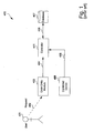
- Fig. 1 shows a prior art arrangement for providing secure access.
- a user 401 makes a request, as depicted by an arrow 402, directed to a code entry module 403.
- the module 403 is typically mounted on the external jamb of a secure door.
- the request 402 is typically a secure code of some type which is compatible with the code entry module 403.
- the request 402 can be a sequence of secret numbers directed to a keypad 403.
- the request 402 can be a biometric signal from the user 401 directed to a corresponding biometric sensor 403.
- a biometric signal is a fingerprint.
- Other physical attributes that can be used to provide biometric signals include voice, retinal or iris pattern, face pattern, palm configuration and so on.
- the code entry module 403 conveys the request 402 by sending a corresponding signal, as depicted by an arrow 404, to a controller 405 which is typically situated in a remote or inaccessible place.
- the controller 405 authenticates the security information provided by the user 401 by interrogating a database 407 as depicted by an arrow 406. If the user 401 is authenticated, and has the appropriate access privileges, then the controller 405 sends an access signal, as depicted by an arrow 408, to a device 409 in order to provide the desired access.
- the device 409 can, for example, be the locking mechanism of a secure door, or can be an electronic lock on a personal computer (PC) which the user 401 desires to access.
- PC personal computer
- a proximity card can also be used to emit the request 402, in which case the code entry module 403 has appropriate functionality.
- the communication infrastructure in Fig. 1 is typically less secure.
- the infrastructure 400 is generally hardwired, with the code entry module 403 generally being mounted on the outside jamb of a secured door.
- the signal path 404 can be over a significant distance in order to reach the controller 405.
- the path 404 represents one weak point in the security system 400, providing an unauthorised person with relatively easy access to the information being transmitted between the code entry module 403 and the controller 405.
- Such an unauthorised person can, given this physical access, decipher the communicated information between the code entry module 403 and the controller 405.
- This captured information can be deciphered, replayed in order to gain the access which rightfully belongs to the user 401, or to enable modification for other subversive purposes.
- Wiegand a communication protocol called "Wiegand" for communication between the code entry module 403 and the controller 405.
- the Wiegand protocol is a simple one-way data protocol that can be modified by increasing or decreasing the bit count to ensure uniqueness of the protocol among different security companies.
- the Wiegand protocol does not secure the information being sent between the code entry module 403 and the controller 405.
- RS 485 is a duplex protocol offering encryption capabilities at both the transmitting and receiving ends, ie. the code entry module 403 and the controller 405 respectively in the present case.
- the length of the path 404 nonetheless provides an attack point for the unauthorised person.
- the Invention provides a method, computer readable medium, system, and transmitter sub-system as set out in the accompanying claims.
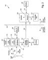
- Fig. 2 is a functional block diagram of an arrangement for providing secure access according to the present disclosure.
- a user 101 makes a request, as depicted by an arrow 102, to a code entry module 103.
- the code entry module 103 includes a biometric sensor 121 and the request 102 takes a form which corresponds to the nature of the sensor 121 in the module 103.
- the biometric sensor 121 in the code entry module 103 is a fingerprint sensor
- the request 102 typically takes the form of a thumb press on a sensor panel (not shown) on the code entry module 103.
- the code entry module 103 interrogates, as depicted by an arrow 104, a user identity database 105.
- a user identity database 105 contains biometric signatures for authorised users against which the request 102 can be authenticated.
- the code entry module 103 sends a signal 106 to a controller/transmitter 107.
- the controller/transmitter 107 checks, as depicted by an arrow 112, the current rolling code in a database 113.
- the controller 107 updates the code and sends the updated code, this being referred to as an access signal, as depicted by an arrow 108 to a controller 109.
- the rolling code protocol offers non-replay encrypted communication.
- the controller 109 tests the rolling code received in the access signal 108 against the most recent rolling code which has been stored in a database 115, this testing being depicted by an arrow 114. If the incoming rolling code forming the access signal 108 is found to be legitimate, then the controller 109 sends a command, as depicted by an arrow 110, to a controlled item 111.
- the controlled item 111 can be a door locking mechanism on a secure door, or an electronic key circuit in a personal computer (PC) that is to be accessed by the user 101.
- PC personal computer
- the controller 109 contains a receiver 118 that receives the transmitted access signal 108 and converts it into a form that is provided, as depicted by an arrow 120, into a form that the controller 109 can use.
- the code entry module 103 also incorporates at least one mechanism for providing feedback to the user 101.
- This mechanism can, for example, take the form or one or more Light Emitting Diodes (LEDs) 122 which can provide visual feedback, depicted by an arrow 123 to the user 101.
- LEDs Light Emitting Diodes
- the mechanism can take the form of an audio signal provided by an audio transducer 124 providing audio feedback 125.
- Fig. 2 The arrangement in Fig. 2 has been described for the case in which the secure code in the access signal 108 used between the sub-systems 116 and 117 is based upon the rolling code. It is noted that this is merely one arrangement, and other secure codes can equally be used. Thus, for example, either of the Bluetooth TM protocol, or the Wi Fi TM protocols can be used.
- Rolling codes provide a substantially non-replayable non-repeatable and encrypted radio frequency data communications scheme for secure messaging. These codes use inherently secure protocols and serial number ciphering techniques which in the present disclosure hide the clear text values required for authentication between the key fob (transmitter) sub-system 116 and the receiver/controller 118/109.
- Rolling codes use a different code variant each time the transmission of the access signal 108 occurs. This is achieved by encrypting the data from the controller 107 with a mathematical algorithm, and ensuring that successive transmissions of the access signal 108 are modified using a code and/or a look-up table known to both the transmitter sub-system 116 and the receiver sub-system 117. Using this approach successive transmissions are modified, resulting in a non-repeatable data transfer, even if the information from the controller 107 remains the same.
- the modification of the code in the access signal 108 for each transmission significantly reduces the likelihood that an intruder can access the information replay the information to thereby gain entry at some later time.
- the sub-system in Fig. 2 falling to the left hand side, as depicted by an arrow 116, of a dashed line 119 can be implemented in a number of different forms.
- the sub-system 116 can for example be incorporated into a remote fob (which is a small portable device carried by the user 101), or alternately can be mounted in a protected enclosure on the outside jamb of a secured door.
- the sub-system 116 communicates with the sub-system 117 on the right hand side of the dashed line 119 via the wireless communication channel used by the access signal 108.
- the sub-system 117 is typically located in an inaccessible area such as a hidden roof space or alternately in a suitable protected area such as an armoured cupboard. The location of the sub-system 117 must of course be consistent with reliable reception of the wireless access signal 108.
- the communication channel uses a wireless transmission medium
- the channel used by the access signal 108 can use a wired medium. This is particularly the case when the transmitter sub-system 116 is mounted in an enclosure on the door jamb rather than in a portable key fob.
- the biometric signature database 105 is shown in Fig. 2 to be part of the transmitter sub-system 116. However, in an alternate arrangement, the biometric signature database 105 can be located in the receiver sub-system 117, in which case the communication 104 between the code entry module 103 and the signature database 105 can also be performed over a secure wireless communication channel such as the one used by the access signal 108. In the event that the secure access system is being applied to providing secure access to a PC, then the secured PC can store the biometric signature of the authorised user in internal memory, and the PC can be integrated into the receiver sub-system 117 of Fig. 1 .
- the sub-system 116 is implemented as a remote fob
- the combination of the biometric verification and the strongly encrypted wireless communication provides a particularly significant advantage over current systems.
- the remote key fob arrangement allows easy installation, since the wired communication path 404 (see Fig. 1 ) is avoided. Other existing wiring elements of the present systems 400 can be used where appropriate.
- the fob incorporates the biometric (eg fingerprint) authentication arrangement, in which case only one biometric signature is stored in the fob. This arrangement reduces the requirements on the central database 115.
- biometric signature eg fingerprint
- the biometric sensor 121 in the code entry module 103 in conjunction with the controller 107 can also check other access privileges of the user 101.
- These access privileges can be contained in the database 105 which can be located either locally in the remote key fob, or in the receiver sub-system 117 as previously described.
- Tom Smith can firstly be authenticated as Tom Smith using the thumb press by Tom on the biometric sensor panel (not shown). After Tom's personal biometric identity is authenticated, the transmitter sub-system 116 can check if Tom Smith is in fact allowed to use the particular door secured by the device 111 on weekends.
- the security screening offered by the described arrangement can range from simple authentication of the user's identity, to more comprehensive access privilege screening.
- the incorporation of the biometric sensor 121 into the code entry module 103 in the form of a remote key fob also means that if the user 101 loses the remote key fob, the user need not be concerned that someone else can use it. Since the finder of the lost key fob will not be able to have his or her biometric signal authenticated by the biometric sensor 121 in the code entry module 103, the lost key fob is useless to anyone apart from the rightful user 101.
- the transmitter sub-system 116 is preferably fabricated in the form of a single integrated circuit (IC) to reduce the possibility of an authorised person bypassing the biometric sensor 121 in the code entry module 103 and directly forcing the controller 107 to emit the rolling code access signal 108.
- IC integrated circuit
- Fig. 3 shows the method of operation of the remote control module (ie the sub-system 116) of Fig. 2 .
- the method 200 commences with a testing step 201 in which the biometric sensor 121 in the code entry module 103 checks whether a biometric signal 102 is being received. If this is not the case, then the method 200 is directed in accordance with an NO arrow back to the step 201 in a loop. If, on the other hand, the biometric signal 102 has been received, then the method 200 is directed in accordance with a YES arrow to a step 202.
- the step 202 compares the received biometric signal 102 with information in the biometric signature database 105 in order to ensure that the biometric signal received 102 is that of the rightful user 101 of the sub-system 116.
- a subsequent testing step 203 checks whether the comparison in the step 202 yields the desired authentication. If the biometric signature matching is authenticated, then the process 200 is directed in accordance with a YES arrow to a step 204.
- the authentication of the biometric signature matching produces an accessibility attribute for the biometric signal 102 in question.
- the accessibility attribute establishes whether and under which conditions access to the controlled item 111 should be granted to a user.
- the accessibility attribute may comprise one or more of an access attribute (granting unconditional access), a duress attribute (granting access but with activation of an alert tone to advise authorities of the duress situation), an alert attribute (sounding a chime indicating that an unauthorised, but not necessarily hostile, person is seeking access, and a telemetry attribute, which represents a communication channel for communicating state information for the transmitter sub-system to the receiver sub-system such as a "low battery” condition.
- the step 204 enables the user 101 to select a control option by providing one or more additional signals (not shown) to the controller 107.
- the control option could enable the user 101 to access one of a number of secure doors after his or her identity has been authenticated in the step 203.
- the controller 107 sends the appropriate access signal 108 to the controller 109.
- the process 200 is then directed in accordance with an arrow 206 back to the step 201.
- the sub-system 116 can be provided with a single biometric sensor 121 in the code entry module 103 which enables the user 101 to select one of four door entry control signals by means of separate buttons on the controller 107 (not shown). This would enable the user 101, after authentication by the biometric sensor 121 in the code entry module 103 and the controller 107 to obtain access to any one of the aforementioned for secure doors.
- the process 200 is directed in accordance with a NO arrow back to the step 201.
- the NO arrow from the step 203 could lead to a disabling step which would disable further operation of the sub-system 116, either immediately upon receipt of the incorrect biometric signal 102, or after a number of attempts to provide the correct biometric signal 102.
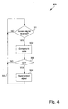
- Fig. 4 shows the method of operation of the control sub-system 117 of Fig. 2 .
- the method 300 commences with a testing step 301 which continuously checks whether the access signal 108 has been received from 107.
- the step 301 is performed by the controller 109. As long as the access signal 108 is not received the process 300 is directed in accordance with a NO arrow in a looping manner back to the step 301.
- the process 300 is directed from the step 301 by means of a YES arrow to a step 302.
- the controller 109 compares the rolling code received by means of the access signal 108 with a reference code in the database 115.
- a subsequent testing step 303 is performed by the controller 109. In the step 303 if the code received on the access signal 108 is successfully matched against the reference code in the database 115 then the process 300 is directed in accordance with a YES arrow to a step 304.
- the controller 109 sends the control signal 110 to the controlled item 111 (for example opening the secured door).
- the process 300 is then directed from the step 304 as depicted by an arrow 305 back to the step 301.
- the process 300 is directed from the step 303 in accordance with a NO arrow back to the step 301.
- the process 300 could be directed, if the code match is negative, from the step 303 to a disabling step which would disable the sub-system 117 if the incorrect code where received once or a number of times.
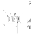
- Fig. 5 shows incorporation of a protocol converter into the arrangement of Fig. 2 .
- the receiver 118 in the controller 109 is able to directly receive and process the rolling code in the access signal 108 in a manner as to provide, as depicted by the arrow 120, the necessary information to the controller 109.
- Fig. 5 shows how an existing controller depicted by a reference numeral 109' that uses Wiegand input signalling can be used in the disclosed arrangement when alarm systems are upgraded.
- Fig. 5 shows how the incoming access signal 108 is received by a receiver 118' as is the case in Fig. 2 .
- Fig. 5 shows incorporation of a protocol converter into the arrangement of Fig. 2 .
- the receiver 118 in the controller 109 is able to directly receive and process the rolling code in the access signal 108 in a manner as to provide, as depicted by the arrow 120, the necessary information to the controller 109.
- Fig. 5 shows how an existing controller depicted by a reference nume
- the receiver 118' provides, as depicted by an arrow 503, the received rolling code from the access signal 108 to a rolling code/Wiegand protocol converter 501.
- the converter 501 converts, as depicted by an arrow 504, the incoming rolling code 503 to a form that can be used by the controller 109' that is designed to handle Wiegand protocol incoming signals. Therefore, the converted incoming signal 504 is in the Wiegand format.
- the converter 501 uses a microprocessor-based arrangement running software code to process the incoming rolling code information 503 and decode this information 503 to clear text form.
- the converter 501 converts this clear text to a Wiegand variable bit-length data stream.
- the receiver 118 performs the conversion of the incoming rolling code access signal 108 to clear text which enables the controller 109 to identify the serial number of the originating key fob sub-system 116 to enable the access rights of the user to be verified.
- the protocol converter 501 approach can be adapted to convert between the incoming rolling code 503 (or any other appropriate secure code) to any other convenient protocol used by the controller 109'.
- the advantage of the rolling code/Wiegand converter 501 is that security system upgrades can be made without replacing Wiegand compatible controller 109'. Accordingly, existing systems as are described in Fig. 1 can be upgraded by replacing the code entry module 403 and the transmission path 404, leaving the other components of the system 400 (ie.; the controller 405, the code database 407, and the controlled item 409, together with existing wiring 408 and 406), largely intact. Minor modifications might however be necessary. When upgrading systems in this manner, the sub-system 116 can either be used in a remote fob configuration, or can be placed in a secure housing on an external door jamb.
- Fig. 6 shows another process 700 of operation of the remote access system.
- the process 700 commences with a step 701 that determines if a biometric signal has been received by the biometric sensor 121 in the code entry module in Fig. 2 . If not, then the process 700 follows a NO arrow back to the step 701. If however a biometric signal has been received, then the process 700 follows a YES arrow to a step 702 that determines if the user ID database 105 in Fig. 2 is empty. This would be the case, for example, if the code entry module is new and has never been used, or if the user 101 has erased all the information in the database 105.
- the process 700 is directed by an arrow 703 to 706 in Fig. 8 which depicts a process 800 dealing with the enrolment or the administration function for loading relevant signatures into the database 105. If on the other hand the database 105 is not empty, then the process 700 is directed to a step 704 that determines if the biometric signal that has been received is an administrator's biometric signal.
- the disclosed remote entry system can accommodate at least three classes of user, namely administrators, (ordinary) users, and duress users.
- the administrators have the ability to amend data stored, for example, in the database 105, while the ordinary users do not have this capability.
- the first user of the code entry module 103 is automatically categorised as an administrator. This first administrator can direct the system 100 to either accept further administrators, or alternately to only accept further ordinary users.
- the present description refers to “users”, in fact it is “fingers” which are the operative entities in system operation when the biometric sensor 121 (see Fig. 2 ) is a fingerprint sensor.
- a single user can enrol two or more of his or her own fingers as separate administrators or (ordinary) users of the system, by storing corresponding fingerprints for corresponding fingers in the database 105 via the enrolment process 800 (see Fig. 8 ).
- the first administrator can provide control information to the code entry module by providing a succession of finger presses to the biometric sensor 121, providing that these successive presses are of the appropriate duration, the appropriate quantity, and are input within a predetermined time.
- the control information is encoded by either or both (a) the number of finger presses and (b) the relative duration of the finger presses. If the successive finger presses are provided within this predetermined time, then the controller 107 accepts the presses as potential control information and checks the input information against a stored set of legal control signals.
- ROM Read Only Memory
- the code entry module 103 has feedback signalling mechanisms 122, implemented for example by a number of LEDs, and 124, implemented by an audio transducer.
- the LEDs 122 and the audio transducer 124 are used by the controller to signal the state of the code entry module 103 to the user 101, and to direct the administration process.
- three LEDs, being Red, Amber and Green are provided.
- step 704 if the step determines that the biometric signal received is an administrator's signal, then the process 700 is directed by a YES arrow to 706 in Fig. 8 as depicted by the arrow 703. If on the other hand, the step 704 indicates that the received biometric signal does not belong to an administrator then the process 700 is directed by a NO arrow to 707 in Fig. 7 .
- Fig. 7 shows the access process 600 by which a biometric signal 102 (see Fig. 2 ) is processed in order to provide access to the controlled item 111, or to take other action.
- the process 600 proceeds to a step 602 that compares the received biometric signature to signatures stored in the database 105.
- a following step 603 determines if the received signal falls into the "duress" category. Signatures in this category indicate that the user 101 is in a coercive situation where, for example, an armed criminal is forcing the user 101 to access the secure facility (such as a bank door).
- step 603 determines that the signature is in the duress class
- a following step 604 prepares a "duress" bit for incorporation into the code access signal 108.
- the aforementioned duress bit is an access attribute of the biometric signal 102. Thereafter the process 600 proceeds to a step 605.
- Modules used in the code entry module for producing the rolling code enable a number of user defined bits to be inserted into the access signal 108, and these bits can be used to effect desired control functions in the receiver sub-system 117.
- the disclosed system 100 utilises four such user bits, namely (a) to indicate that the user belongs to the duress category, (b) to indicate a "battery low” condition, or other desired system state or "telemetry" variable, for the code entry module 103, (c) to indicate that the biometric signal represents a legitimate user in which case the secure access to the controlled item 111 is to be granted, or (d) to indicate that the biometric signal is unknown, in which case the controller 109 in the receiver sub-system 117 sounds an alert tone using a bell (not shown) or the like.
- step 603 determines that the biometric signal is not in the duress class
- the process 600 proceeds according to a NO arrow to the step 605.
- the step 605 determines if the code entry module 103 has a low battery condition, in which event the process 600 proceeds according to a YES arrow to a step 606 that prepares a telemetry bit for insertion into the access signal 108.
- the aforementioned telemetry bit is an access attribute of the biometric signal 102.
- the process proceeds to a step 607.
- step 605 determines that telemetry signalling is not required, then the process 600 proceeds according to a NO arrow to the step 607.
- the step 607 checks the biometric signal against the signatures in the database 105. If the received biometric signal matches a legitimate signature in the database 105, then the process is directed to a step 608 that prepares an "access" bit for insertion into the access signal 108. This access bit directs the controller 109 in the receiver sub-system 117 to provide access to the controlled item 111. The aforementioned access bit is an access attribute of the biometric signal 102.
- the process 600 then proceeds to a step 610.
- step 607 determines that the biometric input signal does not match any legitimate signatures in the database 105, then the process 600 proceeds according to a NO arrow to a step 609 that prepares an "alert" bit for insertion into the access signal 108.
- the aforementioned alert bit is an access attribute of the biometric signal 102. This alert bit directs the controller 109 (a) not to provide access to the controlled item 111, and (b) to provide an alert tone, like ringing a chime or a bell (not shown), to alert personnel in the vicinity of the receiver sub-system 117 that an unauthorised user is attempting to gain access to the controlled item 111.
- the alert bit can also cause a camera mounted near the controlled item 111 to photograph the unauthorised user for later identification of that person.
- the camera can be activated if the person attempting to gain access is unauthorised, and also if the person attempting to gain access is authorised but uses a duress signature.
- An optional additional step can prepare an identification field for insertion into the access signal 108. This sends, to the receiver sub-system 117, ID information that the receiver sub-system can use to construct an audit trail listing which users, having signatures in the database 105, have been provided with access to the controlled item 111.
- the process 600 is then directed to the step 610 which inserts the various user defined bits into the access signal 108 and sends the signal 108 to the receiver sub-system 117. Thereafter, the process 600 is directed by an arrow 611 to 705 in Fig. 6 .
- Fig. 8 shows a process 800 for implementing various enrolment procedures.
- the process 800 commences at 706 from Fig. 6 after which a step 801 determines if the biometric signal is a first administrators input (which is the case if the database 105 is empty). If this is the case, then the process 800 is directed to a step 802 that stores the administrator's signature in the database 105. From a terminology perspective, this first administrator, or rather the first administrator's first finger (in the event that the biometric sensor 121 in Fig. 2 is a fingerprint sensor), is referred to as the "superfinger". Further administrator's fingers are referred to as admin-fingers, and ordinary users fingers are referred to merely as "fingers". The reason that someone would enrol more than one of their own fingers into the system is to ensure that even in the event that one of their enrolled fingers is injured, the person can still operate the system using another enrolled finger.
- step 802 as well as the steps 805, 807 and 809 involve sequences of finger presses on the biometric sensor 121 in conjunction with feedback signals from the LEDs 122 and/or the audio speaker 124.
- the process 800 then proceeds to a step 810 that determines if further enrolment procedures are required. If this is the case, then the process 800 proceeds by a YES arrow back to the step 801. If no further enrolment procedures are required, then the process 800 proceeds by a NO arrow to 705 in Fig. 6 .
- the process 800 proceeds by a NO arrow to a step 803.
- the step 803 determines if a further administrator signature is to be stored. It is noted that all signatures stored in the database are tagged as belonging to one or more of the classes of administrator, ordinary user, and duress users. If a further administrator signature is to be stored, then the process 800 proceeds by a YES arrow to the step 802 that stores the biometric signal as a further administrator's signature.
- the process 800 proceeds according to a NO arrow to a step 804 that determines if a duress signature is to be stored. If this is the case then the process 800 follows a YES arrow to a step 805 that stores a duress signature: The process 800 then proceeds to the step 810. If however the step 804 determines that a duress signature is not required, then the process 800 proceeds by a NO arrow to s step 806.
- the step 806 determines if a further simple signature (ie belonging to an ordinary user) is to be stored. If a further simple signature is to be stored, then the process 800 proceeds by a YES arrow to the step 807 that stores the biometric signal as a further ordinary signature.
- the process 800 proceeds according to a NO arrow to a step 808 that determines if any or all signatures are to be erased from the database 105. If this is the case then the process 800 follows a YES arrow to a step 809 that erases the desired signatures. The process 800 then proceeds to the step 810. If however the step 804 determines that no signatures are to be erased, then the process 800 proceeds by a NO arrow to the step 810.
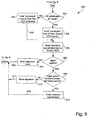
- Fig. 9 shows another enrolment process relating to the example of Fig. 6 .
- the process 900 commences at 706 from Fig. 6 after which a step 901 determines if the received biometric signal comes from the first administrator. If this is the case, then the process 900 proceeds according to a YES arrow to a step 902.
- the step 902 emits an "Enrolment" tone and flashes the green LED once only.
- a step 905 reads the incoming biometric signal which is provided by the user as directed by the Amber LED. When the Amber LED flashes continuously, this directs the user to "Apply Finger".
- step 903 if the incoming biometric signal does not belong to the first administrator, then the process 900 proceeds according to a NO arrow to a step 903.
- the step 903 emits an "Enrolment" tone, and flashes the Red LED in an on-going fashion. Thereafter, the process 900 proceeds according to an arrow 904 to the step 905.
- a step 906 determines whether the incoming biometric signal is legible. If this is not the case, then the process 900 proceeds according to a NO arrow to a step 907. The step 907 emits a "Rejection" tone, after which the process 900 is directed, according to an arrow 908 to 705 in Fig. 6 .
- the process 900 follows a YES arrow to a step 909. The step 909 determines whether the finger press exceeds a predetermined time. If this is not the case, then the process 900 follows a NO arrow to a step 910 which stores the biometric signal, which in the present case is a fingerprint signature. Thereafter the process 900 follows an arrow 911 to 705 in Fig. 6 .
- step 912 erases relevant signatures depending upon the attributes of the incoming biometric signal.
- the incoming biometric signal belongs to an ordinary user
- the ordinary user's signature in the database 105 is erased by the step 912.
- the incoming biometric signal belongs to the first administrator
- all the signatures in the database 105 are erased. Administrators who are not the first administrator can be granted either the same powers as the first administrator in regard to erasure of signatures, or can be granted the same powers as ordinary user in this respect.
- step 912 has completed erasure of the relevant signatures, then the process 900 follows an arrow 913 to 705 in Fig. 6 .
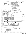
- Fig. 10 is a schematic block diagram of the system in Fig. 2 .
- the disclosed secure access methods are preferably practiced using a computer system arrangement 100', such as that shown in Fig. 10 wherein the processes of Figs. 3-4 , and 6-9 may be implemented as software, such as application program modules executing within the computer system 100'.
- the method steps for providing secure access are effected by instructions in the software that are carried out under direction of the respective processor modules 107 and 109 in the transmitter and receiver sub-systems 116 and 117.
- the instructions may be formed as one or more code modules, each for performing one or more particular tasks.
- the software may also be divided into two separate parts, in which a first part performs the provision of secure access methods and a second part manages a user interface between the first part and the user.
- the software may be stored in a computer readable medium, including the storage devices described below, for example.
- the software is loaded into the transmitter and receiver sub-systems 116 and 117 from the computer readable medium, and then executed under direction of the respective processor modules 107 and 109.
- a computer readable medium having such software or computer program recorded on it is a computer program product.
- the use of the computer program product in the computer preferably effects an advantageous apparatus for provision of secure access.
- the computer system 100' is formed, having regard to the transmitter sub-system 116, by the controller module 107, input devices such as the bio sensor 121, output devices including the LED display 122 and the audio device 124.
- a communication interface/transceiver 1008 is used by the controller module 107 for communicating to and from a communications network 1020.
- Fig. 2 shows the transmitter sub-system 116 communicating with the receiver sub-system 117 using a direct wireless link for the access signal 108, this link used by the access signal 108 can be effected over the network 1020 forming a tandem link comprising 108-1020-108'.
- the aforementioned communications capability can be used to effect communications between the transmitter sub-system 116 and the receiver sub-system 117 either directly or via the Internet, and other network systems, such as a Local Area Network (LAN) or a Wide Area Network (WAN).
- LAN Local Area Network
- WAN Wide Area Network
- the controller module 107 typically includes at least one processor unit 1005, and a memory unit 1006, for example formed from semiconductor random access memory (RAM) and read only memory (ROM).
- the controller module 107 also includes an number of input/output (I/O) interfaces including an audio-video interface 1007 that couples to the LED display 122 and audio speaker 124, an I/O interface 1013 for the biosensor 121, and the interface 1008 for communications.
- the components 1007, 1008, 1005, 1013 and 1006 the controller module 107 typically communicate via an interconnected bus 1004 and in a manner which results in a conventional mode of operation of the controller 107 known to those in the relevant art.
- the application program modules for the transmitter sub-system 116 are resident in the memory 1006 iROM, and are read and controlled in their execution by the processor 1005. Intermediate storage of the program and any data fetched from the bio sensor 121 and the network 1020 may be accomplished using the RAM in the semiconductor memory 1006. In some instances, the application program modules may be supplied to the user encoded into the ROM in the memory 1006. Still further, the software modules can also be loaded into the transmitter sub-system 116 from other computer readable media, say over the network 1020.
- the term "computer readable medium” as used herein refers to any storage or transmission medium that participates in providing instructions and/or data to the transmitter sub-system 116 for execution and/or processing.
- Examples of storage media include floppy disks, magnetic tape, CD-ROM, a hard disk drive, a ROM or integrated circuit, a magneto-optical disk, or a computer readable card such as a PCMCIA card and the like, whether or not such devices are internal or external of the transmitter sub-system 116.
- Examples of transmission media include radio or infra-red transmission channels as well as a network connection to another computer or networked device, and the Internet or Intranets including e-mail transmissions and information recorded on Websites and the like.
- the system 100 can also be used to provide authorised access to lighting systems, building control devices, exterior or remote devices such as air compressors and so on.
- authorised access to lighting systems, building control devices, exterior or remote devices such as air compressors and so on.
- the concept of "secure access” is thus extendible beyond mere access to restricted physical areas.
Landscapes
- Engineering & Computer Science (AREA)
- Computer Security & Cryptography (AREA)
- Theoretical Computer Science (AREA)
- Computer Hardware Design (AREA)
- General Engineering & Computer Science (AREA)
- Computer Networks & Wireless Communication (AREA)
- Physics & Mathematics (AREA)
- General Physics & Mathematics (AREA)
- Software Systems (AREA)
- Signal Processing (AREA)
- Health & Medical Sciences (AREA)
- Computing Systems (AREA)
- General Health & Medical Sciences (AREA)
- Biomedical Technology (AREA)
- Human Computer Interaction (AREA)
- Databases & Information Systems (AREA)
- Bioethics (AREA)
- Lock And Its Accessories (AREA)
- Measurement Of The Respiration, Hearing Ability, Form, And Blood Characteristics Of Living Organisms (AREA)
Claims (14)
- System zum Bereitstellen von Sicherheitszugriff auf ein gesteuertes Objekt, wobei das System umfasst:eine Datenbank biometrischer Signaturen (105);ein Sendersubsystem (116), Folgendes umfassend:einen biometrischen Sensor (121) zum Empfangen eines biometrischen Signals;Mittel (103), um Übereinstimmung des biometrischen Signals mit Elementen der Datenbank biometrischer Signaturen (105) zu prüfen, um dadurch ein Verfügbarkeitsattribut auszugeben; undMittel (107) zum Emittieren eines Sicherheitszugriffssignals, das vom Verfügbarkeitsattribut abhängige Information vermittelt; undein Empfängersubsystem (117), Folgendes umfassend:Mittel zum Empfangen (118) des übertragenen Sicherheitszugriffssignals; undMittel zum Bereitstellen von bedingtem Zugriff (109, 115) auf das gesteuerte Objekt (111) in Abhängigkeit von der Information,worin das Sendersubsystem (116) außerdem Mittel (103) zum Einpflegen in die Datenbank biometrischer Signaturen (105) umfasst, wobei das Einpflegemittel umfasst:Mittel zum Empfangen einer Reihe von Einträgen des biometrischen Signals, wobei die Reihe gemäß mindestens einem der Anzahl der Einträge und einer Dauer eines jeden solchen Eintrags gekennzeichnet ist;Mittel um die Reihe einer Anweisung zuzuweisen; undMittel zum Einpflegen in die Datenbank (105) gemäß der Anweisung.
- System nach Anspruch 1, außerdem umfassend:Mittel zum Bereitstellen eines Signals zum Leiten von Eingabe der Reihe von Einträgen des biometrischen Signals,Mittel, um in das Sicherheitszugriffssignal ein Identifikationsfeld einzufügen, das das biometrische Signal identifiziert, falls das Signal mit einem Element der Datenbank übereinstimmt; undMittel zum Konstruieren eines Prüfpfads von biometrischen Signalen, die dem biometrischen Sensor zum Zweck des Zugriffs auf das gesteuerte Objekt bereitgestellt werden.
- System nach Anspruch 1 oder 2, worin die Datenbank biometrischer Signaturen Signaturen in mindestens einer von Folgenden umfasst: einer Systemadministratorklasse, einer Systembenutzerklasse und einer Zwangsklasse, wobei das Verfügbarkeitsattribut vorzugsweise umfasst:ein Zugriffsattribut, falls das biometrische Signal mit einem Element der Datenbank biometrischer Signaturen übereinstimmt;ein Zwangsattribut, falls das biometrische Signal mit einem Element der Datenbank biometrischer Signaturen übereinstimmt und das Element zur Zwangsklasse gehört; undein Alarmattribut, falls das biometrische Signal mit keinem Element der Datenbank biometrischer Signaturen übereinstimmt.
- System nach einem vorhergehenden Anspruch, worin das gesteuerte Objekt eins von Folgenden ist:ein Verschlussmechanismus einer Tür; undein elektronisches Schloss an einem persönlichen Computer (PC).
- System nach einem vorhergehenden Anspruch, worin der biometrische Sensor auf eins von Folgenden reagiert: Sprache, Retinamuster, Irismuster, Gesichtsmuster und Handflächenkonfiguration, und/oder die Datenbank biometrischer Signaturen mindestens in einem von Folgenden angeordnet ist: dem Sendersubsystem und dem Empfängersubsystem.
- System nach einem vorhergehenden Anspruch, worin der bedingte Zugriff eins von Folgenden umfasst:Bereitstellen von Zugriff auf das gesteuerte Objekt, falls das Verfügbarkeitsattribut ein Zugriffsattribut umfasst;Bereitstellen von Zugriff auf das gesteuerte Objekt und Ertönen eines Alarms, falls das Verfügbarkeitsattribut ein Zwangsattribut umfasst; undVerweigern von Zugriff auf das gesteuerte Objekt und Ertönen eines Alarms, falls das Verfügbarkeitsattribut ein Alarmattribut umfasst.
- System nach Anspruch 1, worin:der biometrische Sensor dazu dient, die Identität eines Benutzers zu authentifizieren;das Mittel zum Emittieren einen Sender zum Übertragen von Information umfasst, die mehr als zwei Zugriffstypen auf das gesteuerte Objekt unter Verwendung eines drahtlosen Sicherheitssignals gewähren kann, das von einer Anforderung vom Benutzer und der Authentifikation der Benutzeridentität abhängt; und das System außerdem ein Steuerfeld zum Empfangen der Information und zum Bereitstellen des angeforderten Sicherheitszugriffs umfasst.
- System nach Anspruch 7, worin das Steuerfeld einen Konvertierer zum Empfangen des drahtlosen Sicherheitssignals und zum Ausgeben der Information einschließt, und/oder der biometrische Sensor die Identität des Benutzers durch Vergleichen einer biometrischen Eingabe vom Benutzer mit einer biometrischen Signatur für den Benutzer in einer biometrischen Datenbank authentifiziert, und/oder der biometrische Sensor, die biometrische Datenbank und der Sender in einer Fernbedienung angeordnet sind.
- System nach Anspruch 7 oder 8, worin das drahtlose Sicherheitssignal einen HF-Träger und einen Rollcode umfasst und der Konvertierer den Rollcode vorzugsweise in das Wiegand-Protokoll konvertiert.
- Sendersubsystem (116) zum Betrieb in einem System (100) zum Bereitstellen von Sicherheitszugriff auf ein gesteuertes Objekt (111), worin das Sendersubsystem (116) umfasst:einen biometrischen Sensor (121) zum Empfangen eines biometrischen Signals;Mittel (103), um Übereinstimmung des biometrischen Signals mit Elementen einer Datenbank biometrischer Signaturen (105) zu prüfen, um dadurch ein Verfügbarkeitsattribut auszugeben; undMittel (107) zum Emittieren eines Sicherheitszugriffssignals, das die vom Verfügbarkeitsattribut abhängige Information vermittelt;worin das Sendersubsystem (116) außerdem Mittel (103) zum Einpflegen in die Datenbank biometrischer Signaturen (105) umfasst, wobei das Einpflegemittel umfasst:Mittel zum Empfangen einer Reihe von Einträgen des biometrischen Signals, wobei die Reihe gemäß mindestens einem der Anzahl der Einträge und einer Dauer eines jeden solchen Eintrags gekennzeichnet ist;Mittel um die Reihe einer Anweisung zuzuweisen; undMittel zum Einpflegen in die Datenbank (105) gemäß der Anweisung.
- Verfahren zum Bereitstellen von Sicherheitszugriff auf ein gesteuertes Objekt (111) in einem System, das Folgendes umfasst: eine Datenbank biometrischer Signaturen (105), ein Sendersubsystem (116), das einen biometrischen Sensor (121) zum Empfangen eines biometrischen Signals umfasst, und Mittel zum Emittieren (107) eines Sicherheitszugriffssignals, das mehr als zwei Zugriffstypen auf das gesteuerte Objekt (111) gewähren kann, und ein Empfängersubsystem (117), das Mittel zum Empfangen(118) des übertragenen Sicherheitszugriffssignals umfasst, und Mittel zum Bereitstellen von bedingtem Zugriff (109, 115) auf das gesteuerte Objekt (111) in Abhängigkeit von Information im Sicherheitszugriffssignal, wobei das Verfahren die folgenden Schritte umfasst:Einpflegen in die Datenbank biometrischer Signaturen (105) durch:Empfangen einer Reihe von Einträgen des biometrischen Signals;Bestimmen von mindestens einem der Anzahl der Einträge und einer Dauer eines jeden solchen Eintrags;Zuweisen der Reihe an eine Anweisung; undEinpflegen in die Datenbank (105) gemäß der Anweisung;Empfangen eines biometrischen Signals (201);Übereinstimmung des biometrischen Signals (202-204) mit Elementen der Datenbank biometrischer Signaturen (105) prüfen, um dadurch ein Verfügbarkeitsattribut auszugeben;Emittieren eines Sicherheitszugriffssignals (205), das vom Verfügbarkeitsattribut abhängige Information vermittelt; undBereitstellen von bedingtem Zugriff (301-304) auf das gesteuerte Objekt (111) in Abhängigkeit von der Information.
- Verfahren nach Anspruch 11, worin der Schritt des Einpflegens in die Datenbank biometrischer Signaturen (105) außerdem den Schritt umfasst, eine biometrische Signatur in die Datenbank biometrischer Signaturen (105) aufzunehmen, folgende Schritte umfassend:Empfangen eines biometrischen Signals; undAufnehmen des biometrischen Signals als eine Administrator-Signatur, falls die Datenbank biometrischer Signaturen leer ist.
- Verfahren nach Anspruch 12, worin der Schritt des Aufnehmens der biometrischen Signatur außerdem das Empfangen eines anderen biometrischen Signals umfasst, um das Aufnehmen des biometrischen Signals als eine Administrator-Signatur zu bestätigen, und vorzugsweise in Abhängigkeit vom Erzeugen eines Feedback-Signals ausgeführt wird, das dazu angepasst ist, die Bereitstellung von mindestens einem von Folgenden zu leiten: das biometrische Signal und das andere biometrische Signal.
- Computerlesbares Medium zum Speichern eines Computerprogramms, das Anweisungen oder Code umfasst, die bei Ausführung durch Prozessoren (107, 109, 1005) die Prozessoren (107, 109, 1005) veranlassen, die Schritte des Verfahrens nach einem der Ansprüche 11 bis 13 auszuführen.
Priority Applications (1)
| Application Number | Priority Date | Filing Date | Title |
|---|---|---|---|
| EP14188004.7A EP2903203A1 (de) | 2003-08-13 | 2004-08-13 | Ferngesteuertes Eingangssystem |
Applications Claiming Priority (2)
| Application Number | Priority Date | Filing Date | Title |
|---|---|---|---|
| AU2003904317A AU2003904317A0 (en) | 2003-08-13 | 2003-08-13 | Remote entry system |
| PCT/AU2004/001083 WO2005018137A1 (en) | 2003-08-13 | 2004-08-13 | Remote entry system |
Related Child Applications (1)
| Application Number | Title | Priority Date | Filing Date |
|---|---|---|---|
| EP14188004.7A Division EP2903203A1 (de) | 2003-08-13 | 2004-08-13 | Ferngesteuertes Eingangssystem |
Publications (3)
| Publication Number | Publication Date |
|---|---|
| EP1661298A1 EP1661298A1 (de) | 2006-05-31 |
| EP1661298A4 EP1661298A4 (de) | 2009-11-04 |
| EP1661298B1 true EP1661298B1 (de) | 2014-10-08 |
Family
ID=32476594
Family Applications (2)
| Application Number | Title | Priority Date | Filing Date |
|---|---|---|---|
| EP14188004.7A Withdrawn EP2903203A1 (de) | 2003-08-13 | 2004-08-13 | Ferngesteuertes Eingangssystem |
| EP04761120.7A Expired - Lifetime EP1661298B1 (de) | 2003-08-13 | 2004-08-13 | Ferneingabesystem |
Family Applications Before (1)
| Application Number | Title | Priority Date | Filing Date |
|---|---|---|---|
| EP14188004.7A Withdrawn EP2903203A1 (de) | 2003-08-13 | 2004-08-13 | Ferngesteuertes Eingangssystem |
Country Status (7)
| Country | Link |
|---|---|
| US (4) | US8266442B2 (de) |
| EP (2) | EP2903203A1 (de) |
| JP (1) | JP2007501981A (de) |
| CN (2) | CN102158473B (de) |
| AU (3) | AU2003904317A0 (de) |
| CA (1) | CA2535434C (de) |
| WO (1) | WO2005018137A1 (de) |
Cited By (1)
| Publication number | Priority date | Publication date | Assignee | Title |
|---|---|---|---|---|
| US11348390B2 (en) | 2016-06-10 | 2022-05-31 | Tapplock Corporation | Padlock device, systems including a padlock device, and methods of operating therefor |
Families Citing this family (51)
| Publication number | Priority date | Publication date | Assignee | Title |
|---|---|---|---|---|
| US7856558B2 (en) * | 2004-10-21 | 2010-12-21 | Honeywell International Inc. | Biometric verification and duress detection system and method |
| USRE48433E1 (en) | 2005-01-27 | 2021-02-09 | The Chamberlain Group, Inc. | Method and apparatus to facilitate transmission of an encrypted rolling code |
| US8422667B2 (en) | 2005-01-27 | 2013-04-16 | The Chamberlain Group, Inc. | Method and apparatus to facilitate transmission of an encrypted rolling code |
| US12556387B2 (en) | 2005-01-27 | 2026-02-17 | The Chamberlain Group Llc | Method and apparatus to facilitate transmission of an encrypted rolling code |
| US9148409B2 (en) | 2005-06-30 | 2015-09-29 | The Chamberlain Group, Inc. | Method and apparatus to facilitate message transmission and reception using different transmission characteristics |
| US8183980B2 (en) | 2005-08-31 | 2012-05-22 | Assa Abloy Ab | Device authentication using a unidirectional protocol |
| FR2904124B1 (fr) † | 2006-07-24 | 2008-10-31 | Rifl S A Sa | Organe de commande intelligent |
| US8108684B2 (en) * | 2006-10-12 | 2012-01-31 | Honeywell International Inc. | Method and system for controlling a security system using near field communication |
| AU2007306965A1 (en) * | 2006-10-13 | 2008-04-17 | Microlatch Pty Ltd | A secure wireless remote entry system |
| EP3270540A1 (de) * | 2007-10-22 | 2018-01-17 | Microlatch Pty Ltd | Sender zum senden eines sicheren zugriffssignals |
| US20090153290A1 (en) * | 2007-12-14 | 2009-06-18 | Farpointe Data, Inc., A California Corporation | Secure interface for access control systems |
| WO2010019593A1 (en) | 2008-08-11 | 2010-02-18 | Assa Abloy Ab | Secure wiegand communications |
| US8443202B2 (en) * | 2009-08-05 | 2013-05-14 | Daon Holdings Limited | Methods and systems for authenticating users |
| JP2013506210A (ja) | 2009-09-30 | 2013-02-21 | インテル コーポレイション | システムのバイオメトリックセキュリティの向上 |
| US8799666B2 (en) | 2009-10-06 | 2014-08-05 | Synaptics Incorporated | Secure user authentication using biometric information |
| CA2742019A1 (en) * | 2010-06-24 | 2011-12-24 | The Chamberlain Group, Inc. | Method and apparatus to facilitate message transmission and reception via wireline using different transmission characteristics |
| US10713341B2 (en) * | 2011-07-13 | 2020-07-14 | Scott F. McNulty | System, method and apparatus for generating acoustic signals based on biometric information |
| JP5584578B2 (ja) * | 2010-10-08 | 2014-09-03 | 富士通株式会社 | 生体情報登録・認証装置及びその登録・認証方法 |
| US9972146B1 (en) | 2010-11-17 | 2018-05-15 | Cypress Semiconductor Corporation | Security system with a wireless security device |
| US8836470B2 (en) | 2010-12-02 | 2014-09-16 | Viscount Security Systems Inc. | System and method for interfacing facility access with control |
| US20120317024A1 (en) * | 2011-06-10 | 2012-12-13 | Aliphcom | Wearable device data security |
| US9069380B2 (en) | 2011-06-10 | 2015-06-30 | Aliphcom | Media device, application, and content management using sensory input |
| US20130019510A1 (en) * | 2011-07-20 | 2013-01-24 | Jason Kemmerer | Firearm locking system |
| CN103858379A (zh) * | 2011-10-11 | 2014-06-11 | 坦戈迈公司 | 对装置用户的认证 |
| US9589399B2 (en) | 2012-07-02 | 2017-03-07 | Synaptics Incorporated | Credential quality assessment engine systems and methods |
| US8937528B2 (en) * | 2012-09-12 | 2015-01-20 | Ford Global Technologies, Llc | Apparatus and method for registering users and managing biometric data thereof in a vehicle |
| WO2014043911A1 (zh) * | 2012-09-24 | 2014-03-27 | 华为技术有限公司 | 用户登录方法及终端 |
| US9196103B2 (en) | 2013-01-30 | 2015-11-24 | International Business Machines Corporation | Entry technology for building automation |
| US9330561B2 (en) * | 2013-03-04 | 2016-05-03 | Hello Inc. | Remote communication systems and methods for communicating with a building gateway control to control building systems and elements |
| CN105378804B (zh) | 2013-03-22 | 2019-07-16 | Utc 消防和保安美国有限公司 | 用于在电子环境中模拟机械锁的操作的方法和用于增强锁的安全性的装置 |
| GB2516837B (en) | 2013-07-31 | 2015-12-09 | Ip Access Ltd | Network elements, wireless communication system and methods therefor |
| WO2016055697A1 (en) * | 2014-10-07 | 2016-04-14 | Teknologian Tutkimuskeskus Vtt Oy | Local trust creation and verification device |
| WO2016177672A1 (en) | 2015-05-01 | 2016-11-10 | Assa Abloy Ab | Split-provisioning of personal wearable and enterprise phone |
| GB2547954B (en) * | 2016-03-03 | 2021-12-22 | Zwipe As | Attack resistant biometric authorised device |
| US10237304B1 (en) * | 2016-08-03 | 2019-03-19 | Symantec Corporation | Systems and methods of administering computer activities based upon emotional intelligence |
| US20180132107A1 (en) * | 2016-11-07 | 2018-05-10 | Mediatek Inc. | Method and associated processor for improving user verification |
| US10452877B2 (en) | 2016-12-16 | 2019-10-22 | Assa Abloy Ab | Methods to combine and auto-configure wiegand and RS485 |
| WO2019035511A1 (ko) * | 2017-08-17 | 2019-02-21 | 주식회사 두올테크 | 건설현장 자원통제관리시스템용 단말기 및 그 단말기 케이스 구조 |
| US10652743B2 (en) | 2017-12-21 | 2020-05-12 | The Chamberlain Group, Inc. | Security system for a moveable barrier operator |
| EP3528066A1 (de) | 2018-02-16 | 2019-08-21 | Rifl | Biometrie-basiertes steuergerät |
| FR3079343B1 (fr) * | 2018-03-22 | 2021-07-09 | Schneider Electric Ind Sas | Procede de consignation d'une fonction d'un appareil electrique et appareil electrique mettant en oeuvre ce procede |
| WO2019226544A1 (en) * | 2018-05-21 | 2019-11-28 | Sensormatic Electronics, LLC | Facial recognition frictionless access control |
| US11074773B1 (en) | 2018-06-27 | 2021-07-27 | The Chamberlain Group, Inc. | Network-based control of movable barrier operators for autonomous vehicles |
| US11423717B2 (en) | 2018-08-01 | 2022-08-23 | The Chamberlain Group Llc | Movable barrier operator and transmitter pairing over a network |
| CN111212393A (zh) | 2018-11-20 | 2020-05-29 | 亚萨合莱有限公司 | 用信号通知胁迫 |
| US11949677B2 (en) * | 2019-04-23 | 2024-04-02 | Microsoft Technology Licensing, Llc | Resource access based on audio signal |
| US10997810B2 (en) | 2019-05-16 | 2021-05-04 | The Chamberlain Group, Inc. | In-vehicle transmitter training |
| US11240026B2 (en) | 2019-05-16 | 2022-02-01 | Blackberry Limited | Devices and methods of managing data |
| US11127410B2 (en) * | 2019-11-12 | 2021-09-21 | Wen-Ta Chiu | Voice decoding device and method thereof |
| KR102322876B1 (ko) * | 2020-01-17 | 2021-11-04 | 엘에스오토모티브테크놀로지스 주식회사 | 사용자 인식 장치 |
| US11295758B2 (en) | 2020-03-20 | 2022-04-05 | Seagate Technology Llc | Trusted listening |
Family Cites Families (36)
| Publication number | Priority date | Publication date | Assignee | Title |
|---|---|---|---|---|
| US4748668A (en) * | 1986-07-09 | 1988-05-31 | Yeda Research And Development Company Limited | Method, apparatus and article for identification and signature |
| CA2004457A1 (en) * | 1988-12-06 | 1990-06-06 | Seigo Igaki | Minutia data extraction in fingerprint identification |
| WO1991007826A1 (en) * | 1989-11-22 | 1991-05-30 | Russell David C | Computer control system |
| JP2788527B2 (ja) | 1990-02-27 | 1998-08-20 | 富士通株式会社 | 指紋照合方法 |
| JPH0830745A (ja) * | 1994-07-20 | 1996-02-02 | Nippon Telegr & Teleph Corp <Ntt> | 個人識別機能付きカード、個人識別機能付きカードの処理システムおよび個人識別機能付きカードの処理方法 |
| US7152045B2 (en) * | 1994-11-28 | 2006-12-19 | Indivos Corporation | Tokenless identification system for authorization of electronic transactions and electronic transmissions |
| US5933515A (en) * | 1996-07-25 | 1999-08-03 | California Institute Of Technology | User identification through sequential input of fingerprints |
| US6038666A (en) | 1997-12-22 | 2000-03-14 | Trw Inc. | Remote identity verification technique using a personal identification device |
| US6151676A (en) * | 1997-12-24 | 2000-11-21 | Philips Electronics North America Corporation | Administration and utilization of secret fresh random numbers in a networked environment |
| US6195447B1 (en) * | 1998-01-16 | 2001-02-27 | Lucent Technologies Inc. | System and method for fingerprint data verification |
| IL123532A0 (en) | 1998-03-03 | 1998-10-30 | Ituran Location & Control Ltd | Personal access code remote control |
| US6353889B1 (en) | 1998-05-13 | 2002-03-05 | Mytec Technologies Inc. | Portable device and method for accessing data key actuated devices |
| US6219439B1 (en) * | 1998-07-09 | 2001-04-17 | Paul M. Burger | Biometric authentication system |
| DE19838421A1 (de) | 1998-08-24 | 2000-03-16 | Siemens Ag | Zugangskontrolleinrichtung zu einem Objekt, insbesondere zu einem Kraftfahrzeug |
| JP3817965B2 (ja) | 1999-04-21 | 2006-09-06 | 富士ゼロックス株式会社 | 検出装置 |
| JP2001052182A (ja) * | 1999-08-13 | 2001-02-23 | Nippon Telegr & Teleph Corp <Ntt> | 個人認証方法及び個人認証プログラムを記録した記録媒体 |
| US6950819B1 (en) | 1999-11-22 | 2005-09-27 | Netscape Communication Corporation | Simplified LDAP access control language system |
| US7054470B2 (en) * | 1999-12-02 | 2006-05-30 | International Business Machines Corporation | System and method for distortion characterization in fingerprint and palm-print image sequences and using this distortion as a behavioral biometrics |
| WO2001071671A2 (en) * | 2000-03-21 | 2001-09-27 | Widcomm, Inc. | System and method for secure user identification with bluetooth enabled transceiver and biometric sensor implemented in a handheld computer |
| AU757159C (en) | 2000-05-16 | 2003-07-03 | Mu Hua Investments Limited | Biometric key |
| JP2001331609A (ja) | 2000-05-19 | 2001-11-30 | Fuji Xerox Co Ltd | サービス提供方法及びサービス提供システム |
| AU2001275823A1 (en) * | 2000-08-03 | 2002-02-18 | Hong-Sik Koo | Method, device, and system for door lock |
| US7010691B2 (en) * | 2000-08-04 | 2006-03-07 | First Data Corporation | ABDS system utilizing security information in authenticating entity access |
| JP2002055959A (ja) * | 2000-08-11 | 2002-02-20 | Mackport Bio-Security Corp | 情報端末、認証システム及び認証方法 |
| AU2001293248A1 (en) * | 2000-10-03 | 2002-04-15 | Abraham R. Zingher | Biometric system and method for detecting duress transactions |
| US7305550B2 (en) * | 2000-12-29 | 2007-12-04 | Intel Corporation | System and method for providing authentication and verification services in an enhanced media gateway |
| US20020112177A1 (en) * | 2001-02-12 | 2002-08-15 | Voltmer William H. | Anonymous biometric authentication |
| JP4390122B2 (ja) * | 2001-03-14 | 2009-12-24 | 富士通株式会社 | バイオメトリック情報を用いた利用者認証システム |
| WO2002095589A1 (en) * | 2001-05-17 | 2002-11-28 | Identix Incorporated | Mobile identity verification |
| US7167987B2 (en) * | 2001-08-29 | 2007-01-23 | Hewlett-Packard Development Company, L.P. | Use of biometrics to provide physical and logic access to computer devices |
| US20030051173A1 (en) * | 2001-09-10 | 2003-03-13 | Krueger Steven J. | Computer security system |
| JP2003132032A (ja) | 2001-10-24 | 2003-05-09 | Minoru Ikeda | 個人認証システム、認証装置、個人認証方法、プログラム、および、記録媒体 |
| US7174017B2 (en) * | 2002-03-04 | 2007-02-06 | Lenovo Singapore Pte, Ltd | Decryption system for encrypted audio |
| JP4686128B2 (ja) * | 2002-03-06 | 2011-05-18 | トモセラピー インコーポレイテッド | 放射線送達装置の制御方法及び放射線治療を送達するシステム |
| US6992562B2 (en) * | 2003-06-10 | 2006-01-31 | Visteon Global Technologies, Inc. | Biometric keyless entry system |
| WO2006118555A1 (en) | 2005-03-31 | 2006-11-09 | Brian Scott Miller | Biometric control of equipment |
-
2003
- 2003-08-13 AU AU2003904317A patent/AU2003904317A0/en not_active Abandoned
-
2004
- 2004-08-13 EP EP14188004.7A patent/EP2903203A1/de not_active Withdrawn
- 2004-08-13 CA CA2535434A patent/CA2535434C/en not_active Expired - Lifetime
- 2004-08-13 WO PCT/AU2004/001083 patent/WO2005018137A1/en not_active Ceased
- 2004-08-13 JP JP2006522849A patent/JP2007501981A/ja active Pending
- 2004-08-13 CN CN2011100377818A patent/CN102158473B/zh not_active Expired - Lifetime
- 2004-08-13 EP EP04761120.7A patent/EP1661298B1/de not_active Expired - Lifetime
- 2004-08-13 CN CNA2004800232234A patent/CN1836399A/zh active Pending
- 2004-08-13 AU AU2004301168A patent/AU2004301168B2/en not_active Expired
- 2004-08-13 US US10/568,207 patent/US8266442B2/en active Active
-
2009
- 2009-04-02 AU AU2009201293A patent/AU2009201293B2/en not_active Expired
-
2012
- 2012-08-10 US US13/572,166 patent/US9269208B2/en not_active Expired - Lifetime
-
2016
- 2016-01-19 US US15/000,818 patent/US9665705B2/en not_active Expired - Lifetime
-
2017
- 2017-05-11 US US15/592,809 patent/US20170249476A1/en not_active Abandoned
Cited By (1)
| Publication number | Priority date | Publication date | Assignee | Title |
|---|---|---|---|---|
| US11348390B2 (en) | 2016-06-10 | 2022-05-31 | Tapplock Corporation | Padlock device, systems including a padlock device, and methods of operating therefor |
Also Published As
| Publication number | Publication date |
|---|---|
| EP2903203A1 (de) | 2015-08-05 |
| AU2003904317A0 (en) | 2003-08-28 |
| US20080229400A1 (en) | 2008-09-18 |
| AU2009201293A1 (en) | 2009-04-23 |
| EP1661298A1 (de) | 2006-05-31 |
| CN102158473A (zh) | 2011-08-17 |
| WO2005018137A1 (en) | 2005-02-24 |
| AU2004301168B2 (en) | 2009-03-19 |
| CN102158473B (zh) | 2013-02-13 |
| JP2007501981A (ja) | 2007-02-01 |
| AU2009201293B2 (en) | 2012-09-27 |
| US20170249476A1 (en) | 2017-08-31 |
| CA2535434A1 (en) | 2005-02-24 |
| EP1661298A4 (de) | 2009-11-04 |
| CA2535434C (en) | 2016-07-19 |
| CN1836399A (zh) | 2006-09-20 |
| AU2004301168A1 (en) | 2005-02-24 |
| US8266442B2 (en) | 2012-09-11 |
| US20120311343A1 (en) | 2012-12-06 |
| US9665705B2 (en) | 2017-05-30 |
| US20160132672A1 (en) | 2016-05-12 |
| US9269208B2 (en) | 2016-02-23 |
Similar Documents
| Publication | Publication Date | Title |
|---|---|---|
| EP1661298B1 (de) | Ferneingabesystem | |
| US12481742B2 (en) | Locking device biometric access | |
| US8112278B2 (en) | Enhancing the response of biometric access systems | |
| JP2008057129A (ja) | 入室管理システムおよび入室管理方法 | |
| US9111084B2 (en) | Authentication platform and related method of operation | |
| AU2009100853B4 (en) | A secure wireless remote entry system | |
| US20030014642A1 (en) | Security arrangement | |
| US20230155836A1 (en) | Secure serverless multi-factor authentication | |
| Ansari et al. | Mechanism to Identify Legitimate Vehicle User in Remote Keyless Entry System | |
| US10645070B2 (en) | Securitization of temporal digital communications via authentication and validation for wireless user and access devices | |
| KR102883873B1 (ko) | 출입통제를 위한 다중 인증 처리용 허브 장치 및 이를 포함하는 다중 인증 처리용 중계 시스템 | |
| AU2005316195A1 (en) | Enhancing the response of biometric access systems | |
| WO1999045717A1 (en) | Personal access code remote control | |
| CN109614839A (zh) | 出租车的管理方法、装置、车辆及远程服务器 |
Legal Events
| Date | Code | Title | Description |
|---|---|---|---|
| PUAI | Public reference made under article 153(3) epc to a published international application that has entered the european phase |
Free format text: ORIGINAL CODE: 0009012 |
|
| 17P | Request for examination filed |
Effective date: 20060313 |
|
| AK | Designated contracting states |
Kind code of ref document: A1 Designated state(s): AT BE BG CH CY CZ DE DK EE ES FI FR GB GR HU IE IT LI LU MC NL PL PT RO SE SI SK TR |
|
| DAX | Request for extension of the european patent (deleted) | ||
| A4 | Supplementary search report drawn up and despatched |
Effective date: 20091006 |
|
| 17Q | First examination report despatched |
Effective date: 20100709 |
|
| R17C | First examination report despatched (corrected) |
Effective date: 20100716 |
|
| REG | Reference to a national code |
Ref country code: DE Ref legal event code: R079 Ref document number: 602004045954 Country of ref document: DE Free format text: PREVIOUS MAIN CLASS: H04L0009320000 Ipc: G06F0021320000 |
|
| GRAP | Despatch of communication of intention to grant a patent |
Free format text: ORIGINAL CODE: EPIDOSNIGR1 |
|
| RIC1 | Information provided on ipc code assigned before grant |
Ipc: H04W 12/08 20090101ALI20130701BHEP Ipc: G06F 21/35 20130101ALI20130701BHEP Ipc: H04W 84/18 20090101ALI20130701BHEP Ipc: H04L 29/06 20060101ALI20130701BHEP Ipc: G07C 9/00 20060101ALI20130701BHEP Ipc: H04W 84/12 20090101ALI20130701BHEP Ipc: G06F 21/32 20130101AFI20130701BHEP |
|
| INTG | Intention to grant announced |
Effective date: 20130806 |
|
| GRAP | Despatch of communication of intention to grant a patent |
Free format text: ORIGINAL CODE: EPIDOSNIGR1 |
|
| INTG | Intention to grant announced |
Effective date: 20140429 |
|
| GRAS | Grant fee paid |
Free format text: ORIGINAL CODE: EPIDOSNIGR3 |
|
| GRAA | (expected) grant |
Free format text: ORIGINAL CODE: 0009210 |
|
| AK | Designated contracting states |
Kind code of ref document: B1 Designated state(s): AT BE BG CH CY CZ DE DK EE ES FI FR GB GR HU IE IT LI LU MC NL PL PT RO SE SI SK TR |
|
| REG | Reference to a national code |
Ref country code: GB Ref legal event code: FG4D Ref country code: DE Ref legal event code: R081 Ref document number: 602004045954 Country of ref document: DE Owner name: SECURICOM (NSW) PTY LTD, MERRIMAC, AU Free format text: FORMER OWNER: SECURICOM (NSW) PTY. LTD., RAMSGATE, NEW SOUTH WALES, AU |
|
| REG | Reference to a national code |
Ref country code: CH Ref legal event code: EP Ref country code: AT Ref legal event code: REF Ref document number: 690974 Country of ref document: AT Kind code of ref document: T Effective date: 20141015 |
|
| REG | Reference to a national code |
Ref country code: IE Ref legal event code: FG4D |
|
| REG | Reference to a national code |
Ref country code: DE Ref legal event code: R096 Ref document number: 602004045954 Country of ref document: DE Effective date: 20141113 |
|
| REG | Reference to a national code |
Ref country code: DE Ref legal event code: R081 Ref document number: 602004045954 Country of ref document: DE Owner name: SECURICOM (NSW) PTY LTD, MERRIMAC, AU Free format text: FORMER OWNER: SECURICOM (NSW) PTY. LTD., RAMSGATE, NEW SOUTH WALES, AU |
|
| RAP2 | Party data changed (patent owner data changed or rights of a patent transferred) |
Owner name: MICROLATCH LIMITED |
|
| REG | Reference to a national code |
Ref country code: NL Ref legal event code: T3 |
|
| REG | Reference to a national code |
Ref country code: AT Ref legal event code: MK05 Ref document number: 690974 Country of ref document: AT Kind code of ref document: T Effective date: 20141008 |
|
| PG25 | Lapsed in a contracting state [announced via postgrant information from national office to epo] |
Ref country code: PT Free format text: LAPSE BECAUSE OF FAILURE TO SUBMIT A TRANSLATION OF THE DESCRIPTION OR TO PAY THE FEE WITHIN THE PRESCRIBED TIME-LIMIT Effective date: 20150209 Ref country code: FI Free format text: LAPSE BECAUSE OF FAILURE TO SUBMIT A TRANSLATION OF THE DESCRIPTION OR TO PAY THE FEE WITHIN THE PRESCRIBED TIME-LIMIT Effective date: 20141008 Ref country code: ES Free format text: LAPSE BECAUSE OF FAILURE TO SUBMIT A TRANSLATION OF THE DESCRIPTION OR TO PAY THE FEE WITHIN THE PRESCRIBED TIME-LIMIT Effective date: 20141008 |
|
| PG25 | Lapsed in a contracting state [announced via postgrant information from national office to epo] |
Ref country code: CY Free format text: LAPSE BECAUSE OF FAILURE TO SUBMIT A TRANSLATION OF THE DESCRIPTION OR TO PAY THE FEE WITHIN THE PRESCRIBED TIME-LIMIT Effective date: 20141008 Ref country code: AT Free format text: LAPSE BECAUSE OF FAILURE TO SUBMIT A TRANSLATION OF THE DESCRIPTION OR TO PAY THE FEE WITHIN THE PRESCRIBED TIME-LIMIT Effective date: 20141008 Ref country code: SE Free format text: LAPSE BECAUSE OF FAILURE TO SUBMIT A TRANSLATION OF THE DESCRIPTION OR TO PAY THE FEE WITHIN THE PRESCRIBED TIME-LIMIT Effective date: 20141008 Ref country code: PL Free format text: LAPSE BECAUSE OF FAILURE TO SUBMIT A TRANSLATION OF THE DESCRIPTION OR TO PAY THE FEE WITHIN THE PRESCRIBED TIME-LIMIT Effective date: 20141008 Ref country code: GR Free format text: LAPSE BECAUSE OF FAILURE TO SUBMIT A TRANSLATION OF THE DESCRIPTION OR TO PAY THE FEE WITHIN THE PRESCRIBED TIME-LIMIT Effective date: 20150109 |
|
| REG | Reference to a national code |
Ref country code: DE Ref legal event code: R097 Ref document number: 602004045954 Country of ref document: DE |
|
| PG25 | Lapsed in a contracting state [announced via postgrant information from national office to epo] |
Ref country code: RO Free format text: LAPSE BECAUSE OF FAILURE TO SUBMIT A TRANSLATION OF THE DESCRIPTION OR TO PAY THE FEE WITHIN THE PRESCRIBED TIME-LIMIT Effective date: 20141008 Ref country code: DK Free format text: LAPSE BECAUSE OF FAILURE TO SUBMIT A TRANSLATION OF THE DESCRIPTION OR TO PAY THE FEE WITHIN THE PRESCRIBED TIME-LIMIT Effective date: 20141008 Ref country code: SK Free format text: LAPSE BECAUSE OF FAILURE TO SUBMIT A TRANSLATION OF THE DESCRIPTION OR TO PAY THE FEE WITHIN THE PRESCRIBED TIME-LIMIT Effective date: 20141008 Ref country code: CZ Free format text: LAPSE BECAUSE OF FAILURE TO SUBMIT A TRANSLATION OF THE DESCRIPTION OR TO PAY THE FEE WITHIN THE PRESCRIBED TIME-LIMIT Effective date: 20141008 Ref country code: EE Free format text: LAPSE BECAUSE OF FAILURE TO SUBMIT A TRANSLATION OF THE DESCRIPTION OR TO PAY THE FEE WITHIN THE PRESCRIBED TIME-LIMIT Effective date: 20141008 |
|
| PLBE | No opposition filed within time limit |
Free format text: ORIGINAL CODE: 0009261 |
|
| STAA | Information on the status of an ep patent application or granted ep patent |
Free format text: STATUS: NO OPPOSITION FILED WITHIN TIME LIMIT |
|
| PG25 | Lapsed in a contracting state [announced via postgrant information from national office to epo] |
Ref country code: IT Free format text: LAPSE BECAUSE OF FAILURE TO SUBMIT A TRANSLATION OF THE DESCRIPTION OR TO PAY THE FEE WITHIN THE PRESCRIBED TIME-LIMIT Effective date: 20141008 |
|
| 26N | No opposition filed |
Effective date: 20150709 |
|
| PG25 | Lapsed in a contracting state [announced via postgrant information from national office to epo] |
Ref country code: SI Free format text: LAPSE BECAUSE OF FAILURE TO SUBMIT A TRANSLATION OF THE DESCRIPTION OR TO PAY THE FEE WITHIN THE PRESCRIBED TIME-LIMIT Effective date: 20141008 |
|
| PG25 | Lapsed in a contracting state [announced via postgrant information from national office to epo] |
Ref country code: LU Free format text: LAPSE BECAUSE OF FAILURE TO SUBMIT A TRANSLATION OF THE DESCRIPTION OR TO PAY THE FEE WITHIN THE PRESCRIBED TIME-LIMIT Effective date: 20150813 Ref country code: MC Free format text: LAPSE BECAUSE OF FAILURE TO SUBMIT A TRANSLATION OF THE DESCRIPTION OR TO PAY THE FEE WITHIN THE PRESCRIBED TIME-LIMIT Effective date: 20141008 |
|
| REG | Reference to a national code |
Ref country code: CH Ref legal event code: PL |
|
| PG25 | Lapsed in a contracting state [announced via postgrant information from national office to epo] |
Ref country code: LI Free format text: LAPSE BECAUSE OF NON-PAYMENT OF DUE FEES Effective date: 20150831 Ref country code: CH Free format text: LAPSE BECAUSE OF NON-PAYMENT OF DUE FEES Effective date: 20150831 |
|
| REG | Reference to a national code |
Ref country code: IE Ref legal event code: MM4A |
|
| PG25 | Lapsed in a contracting state [announced via postgrant information from national office to epo] |
Ref country code: IE Free format text: LAPSE BECAUSE OF NON-PAYMENT OF DUE FEES Effective date: 20150813 |
|
| REG | Reference to a national code |
Ref country code: FR Ref legal event code: PLFP Year of fee payment: 13 |
|
| REG | Reference to a national code |
Ref country code: GB Ref legal event code: 732E Free format text: REGISTERED BETWEEN 20170413 AND 20170419 |
|
| PG25 | Lapsed in a contracting state [announced via postgrant information from national office to epo] |
Ref country code: HU Free format text: LAPSE BECAUSE OF FAILURE TO SUBMIT A TRANSLATION OF THE DESCRIPTION OR TO PAY THE FEE WITHIN THE PRESCRIBED TIME-LIMIT; INVALID AB INITIO Effective date: 20040813 Ref country code: BG Free format text: LAPSE BECAUSE OF FAILURE TO SUBMIT A TRANSLATION OF THE DESCRIPTION OR TO PAY THE FEE WITHIN THE PRESCRIBED TIME-LIMIT Effective date: 20141008 |
|
| PG25 | Lapsed in a contracting state [announced via postgrant information from national office to epo] |
Ref country code: TR Free format text: LAPSE BECAUSE OF FAILURE TO SUBMIT A TRANSLATION OF THE DESCRIPTION OR TO PAY THE FEE WITHIN THE PRESCRIBED TIME-LIMIT Effective date: 20141008 |
|
| REG | Reference to a national code |
Ref country code: FR Ref legal event code: PLFP Year of fee payment: 14 |
|
| REG | Reference to a national code |
Ref country code: NL Ref legal event code: PD Owner name: SECURICOM (NSW) PTY LTD; AU Free format text: DETAILS ASSIGNMENT: CHANGE OF OWNER(S), ASSIGNMENT; FORMER OWNER NAME: MICROLATCH LIMITED Effective date: 20170914 |
|
| REG | Reference to a national code |
Ref country code: DE Ref legal event code: R082 Ref document number: 602004045954 Country of ref document: DE Representative=s name: PATENT- UND RECHTSANWAELTE ULLRICH & NAUMANN P, DE Ref country code: DE Ref legal event code: R081 Ref document number: 602004045954 Country of ref document: DE Owner name: CPC PATENT TECHNOLOGIES PTY LTD., SURFERS PARA, AU Free format text: FORMER OWNER: MICROLATCH LTD., WELWYN GARDEN CITY, HERTFORDSHIRE, GB Ref country code: DE Ref legal event code: R082 Ref document number: 602004045954 Country of ref document: DE Representative=s name: PATENTANWALTSKANZLEI MEYER, DE Ref country code: DE Ref legal event code: R081 Ref document number: 602004045954 Country of ref document: DE Owner name: SECURICOM (NSW) PTY LTD, MERRIMAC, AU Free format text: FORMER OWNER: MICROLATCH LTD., WELWYN GARDEN CITY, HERTFORDSHIRE, GB |
|
| REG | Reference to a national code |
Ref country code: BE Ref legal event code: FP Effective date: 20150108 Ref country code: BE Ref legal event code: PD Owner name: SECURICOM (NSW) PTY LTD; AU Free format text: DETAILS ASSIGNMENT: CHANGE OF OWNER(S), AFFECTATION / CESSION; FORMER OWNER NAME: MICROLATCH LIMITED Effective date: 20171027 |
|
| REG | Reference to a national code |
Ref country code: FR Ref legal event code: CA Effective date: 20180207 |
|
| REG | Reference to a national code |
Ref country code: FR Ref legal event code: TP Owner name: SECURICOM (NSW) PTY LTD, AU Effective date: 20180212 |
|
| REG | Reference to a national code |
Ref country code: DE Ref legal event code: R082 Ref document number: 602004045954 Country of ref document: DE Representative=s name: ULLRICH & NAUMANN PATENT- UND RECHTSANWAELTE, , DE Ref country code: DE Ref legal event code: R082 Ref document number: 602004045954 Country of ref document: DE Representative=s name: PATENT- UND RECHTSANWAELTE ULLRICH & NAUMANN P, DE |
|
| REG | Reference to a national code |
Ref country code: DE Ref legal event code: R082 Ref document number: 602004045954 Country of ref document: DE Representative=s name: PATENT- UND RECHTSANWAELTE ULLRICH & NAUMANN P, DE Ref country code: DE Ref legal event code: R081 Ref document number: 602004045954 Country of ref document: DE Owner name: CPC PATENT TECHNOLOGIES PTY LTD., SURFERS PARA, AU Free format text: FORMER OWNER: SECURICOM (NSW) PTY LTD, MERRIMAC, QUEENSLAND, AU |
|
| REG | Reference to a national code |
Ref country code: BE Ref legal event code: PD Owner name: CPC PATENT TECHNOLOGIES PTY LTD; AU Free format text: DETAILS ASSIGNMENT: CHANGE OF OWNER(S), CESSION; FORMER OWNER NAME: SECURICOM (NSW) PTY LTD Effective date: 20190827 |
|
| REG | Reference to a national code |
Ref country code: GB Ref legal event code: 732E Free format text: REGISTERED BETWEEN 20191003 AND 20191009 |
|
| REG | Reference to a national code |
Ref country code: NL Ref legal event code: PD Owner name: CPC PATENT TECHNOLOGIES PTY LTD; AU Free format text: DETAILS ASSIGNMENT: CHANGE OF OWNER(S), ASSIGNMENT; FORMER OWNER NAME: SECURICOM (NSW) PTY LTD Effective date: 20200828 |
|
| PGFP | Annual fee paid to national office [announced via postgrant information from national office to epo] |
Ref country code: NL Payment date: 20230808 Year of fee payment: 20 |
|
| PGFP | Annual fee paid to national office [announced via postgrant information from national office to epo] |
Ref country code: GB Payment date: 20230731 Year of fee payment: 20 |
|
| PGFP | Annual fee paid to national office [announced via postgrant information from national office to epo] |
Ref country code: FR Payment date: 20230801 Year of fee payment: 20 Ref country code: DE Payment date: 20230801 Year of fee payment: 20 Ref country code: BE Payment date: 20230808 Year of fee payment: 20 |
|
| REG | Reference to a national code |
Ref country code: DE Ref legal event code: R071 Ref document number: 602004045954 Country of ref document: DE |
|
| REG | Reference to a national code |
Ref country code: NL Ref legal event code: MK Effective date: 20240812 |
|
| REG | Reference to a national code |
Ref country code: BE Ref legal event code: MK Effective date: 20240813 |
|
| REG | Reference to a national code |
Ref country code: GB Ref legal event code: PE20 Expiry date: 20240812 |
|
| PG25 | Lapsed in a contracting state [announced via postgrant information from national office to epo] |
Ref country code: GB Free format text: LAPSE BECAUSE OF EXPIRATION OF PROTECTION Effective date: 20240812 |
|
| PG25 | Lapsed in a contracting state [announced via postgrant information from national office to epo] |
Ref country code: GB Free format text: LAPSE BECAUSE OF EXPIRATION OF PROTECTION Effective date: 20240812 |