EP1659923B1 - Otoscopic tip element and related method of use - Google Patents
Otoscopic tip element and related method of use Download PDFInfo
- Publication number
- EP1659923B1 EP1659923B1 EP04786112.5A EP04786112A EP1659923B1 EP 1659923 B1 EP1659923 B1 EP 1659923B1 EP 04786112 A EP04786112 A EP 04786112A EP 1659923 B1 EP1659923 B1 EP 1659923B1
- Authority
- EP
- European Patent Office
- Prior art keywords
- tip element
- tip
- recited
- otoscope
- instrument
- Prior art date
- Legal status (The legal status is an assumption and is not a legal conclusion. Google has not performed a legal analysis and makes no representation as to the accuracy of the status listed.)
- Expired - Lifetime
Links
- 238000000034 method Methods 0.000 title claims description 12
- 230000007246 mechanism Effects 0.000 claims description 41
- 210000003454 tympanic membrane Anatomy 0.000 claims description 25
- 238000007789 sealing Methods 0.000 claims description 8
- 238000004519 manufacturing process Methods 0.000 claims description 5
- 238000004091 panning Methods 0.000 claims description 3
- 239000004743 Polypropylene Substances 0.000 claims description 2
- 239000004033 plastic Substances 0.000 claims description 2
- -1 polypropylene Polymers 0.000 claims description 2
- 229920001155 polypropylene Polymers 0.000 claims description 2
- 238000003780 insertion Methods 0.000 description 29
- 230000037431 insertion Effects 0.000 description 29
- 230000003287 optical effect Effects 0.000 description 22
- 210000000613 ear canal Anatomy 0.000 description 12
- 238000003384 imaging method Methods 0.000 description 10
- 238000013461 design Methods 0.000 description 9
- 210000001747 pupil Anatomy 0.000 description 9
- 230000008901 benefit Effects 0.000 description 8
- 238000005286 illumination Methods 0.000 description 7
- 238000002578 otoscopy Methods 0.000 description 6
- 238000012800 visualization Methods 0.000 description 4
- 230000003044 adaptive effect Effects 0.000 description 3
- 238000012864 cross contamination Methods 0.000 description 3
- 210000003128 head Anatomy 0.000 description 3
- 230000000717 retained effect Effects 0.000 description 3
- 210000002939 cerumen Anatomy 0.000 description 2
- 230000006835 compression Effects 0.000 description 2
- 238000007906 compression Methods 0.000 description 2
- 238000010276 construction Methods 0.000 description 2
- 238000012986 modification Methods 0.000 description 2
- 230000004048 modification Effects 0.000 description 2
- 239000013307 optical fiber Substances 0.000 description 2
- 230000036961 partial effect Effects 0.000 description 2
- 230000008569 process Effects 0.000 description 2
- 230000000007 visual effect Effects 0.000 description 2
- 235000001674 Agaricus brunnescens Nutrition 0.000 description 1
- 241000156948 Aphantopus hyperantus Species 0.000 description 1
- 0 CC1=CC(C*)CC1 Chemical compound CC1=CC(C*)CC1 0.000 description 1
- 206010050337 Cerumen impaction Diseases 0.000 description 1
- 241001481828 Glyptocephalus cynoglossus Species 0.000 description 1
- 230000004308 accommodation Effects 0.000 description 1
- 239000000853 adhesive Substances 0.000 description 1
- 230000001070 adhesive effect Effects 0.000 description 1
- 210000003484 anatomy Anatomy 0.000 description 1
- 230000004323 axial length Effects 0.000 description 1
- 230000005540 biological transmission Effects 0.000 description 1
- 230000003749 cleanliness Effects 0.000 description 1
- 230000001010 compromised effect Effects 0.000 description 1
- 230000007812 deficiency Effects 0.000 description 1
- 238000003745 diagnosis Methods 0.000 description 1
- 238000002405 diagnostic procedure Methods 0.000 description 1
- 238000010586 diagram Methods 0.000 description 1
- 210000005069 ears Anatomy 0.000 description 1
- 229920001971 elastomer Polymers 0.000 description 1
- 239000000806 elastomer Substances 0.000 description 1
- 239000000835 fiber Substances 0.000 description 1
- 230000036541 health Effects 0.000 description 1
- 230000002452 interceptive effect Effects 0.000 description 1
- 230000000670 limiting effect Effects 0.000 description 1
- 239000003550 marker Substances 0.000 description 1
- 239000000463 material Substances 0.000 description 1
- 238000000465 moulding Methods 0.000 description 1
- 238000012634 optical imaging Methods 0.000 description 1
- 238000000926 separation method Methods 0.000 description 1
- 239000007787 solid Substances 0.000 description 1
- 125000006850 spacer group Chemical group 0.000 description 1
- 238000003860 storage Methods 0.000 description 1
- 238000012549 training Methods 0.000 description 1
Images






Classifications
-
- A—HUMAN NECESSITIES
- A61—MEDICAL OR VETERINARY SCIENCE; HYGIENE
- A61B—DIAGNOSIS; SURGERY; IDENTIFICATION
- A61B1/00—Instruments for performing medical examinations of the interior of cavities or tubes of the body by visual or photographical inspection, e.g. endoscopes; Illuminating arrangements therefor
- A61B1/227—Instruments for performing medical examinations of the interior of cavities or tubes of the body by visual or photographical inspection, e.g. endoscopes; Illuminating arrangements therefor for ears, i.e. otoscopes
Definitions
- This invention relates generally to the field of otoscopy and in particular to an improved otoscopic instrument and at least one improved releasably attachable tip element for use with otoscopic apparatus.
- Otoscopes are hand-held instruments that are commonly known in the medical diagnostic instrument field by practitioners and health care providers primarily for examining the ear, including the tympanic membrane, of a patient.
- a typical otoscope is capable of being held in the hand of a practitioner and includes an instrument head having a distal frusto-conical insertion portion that permits overlying attachment of a disposable speculum tip.
- the disposable speculum tip is also preferably designed with a frusto-conical configuration to permit insertion to only an appropriate distance into the ear canal of the patient.
- the target e.g., the tympanic membrane
- the target is then viewed via a lens located in the proximal end of the instrument head, the lens being aligned optically with the distal tip opening of the insertion portion to permit user viewing. Often, the lens magnifies the view of the target.
- a video camera or at least one solid state imaging element can be used to view the target in lieu of the lens, the image as processed being transmitted to a video monitor for display.
- the instrument head can include a receiving port for a pneumatic bulb, permitting insufflation (e.g., pneumatic otoscopy).
- pneumatic bulb permitting insufflation (e.g., pneumatic otoscopy).
- any presently known otoscope tip would either optimize for only one or two of the above attributes, or perform moderately on a few of them.
- US 2003/0063386 A1 shows an otoscope assembly attachment. This attachment has ribs, allowing the attachment to be detachably received by a housing.
- US 6,383,133 B1 describes an otoscope kit including an adapter for removably mounting to the otoscope head.
- the adapter has a helical slit about its periphery.
- the kit includes at least one speculum for mounting on the adapter.
- the speculum has a projection for engaging the slit for drawing the speculum into close contact with the adapter to removably secure the speculum to the adapter during use.
- a disposable otoscope tip system is described in US 6,190,310 B1 and US 6,213,938 B1 .
- a conical member that is secured to the receptacle has a first and second open end.
- the first open end includes a lip and has a greater diameter than the second open end.
- the first open end of the conical member is connected to the receptacle by a shoulder which extends radially inward from an inner surface of a neck to secure the lip therein.
- This objective is especially important in that space in a physician/practitioner's office can be an issue, as well as the logistics and other issues that are often associated with managing various multiple tips.
- a tip element for securing to an otoscope, said tip element including a substantially axisymmetric body having a distal open end and a proximal open end, the tip element having at least one external engagement feature extending radially from the proximal end, the at least one external engagement feature being adapted for engaging a tip attachment mechanism of an otoscope.
- the at least one external engagement feature of the herein described tip element preferably is defined by a circumferential securing portion that is sized to fit within a securing slot of a tip attachment mechanism of an otoscope when the tip element is twisted thereupon in a first predetermined direction.
- the at least one external engagement feature further includes at least one axial portion depending from the circumferential securing portion, the at least one axial portion extending axially in a direction toward the distal open end of the tip element.
- at least one axial portion depending from the circumferential securing portion, the at least one axial portion extending axially in a direction toward the distal open end of the tip element.
- three (3) external engagement features, as described above, are provided; though this number can be suitably varied.
- a plurality of axial gripping ribs can also be provided on the exterior of the tip element, some or all of these ribs including the axial portions of the external engagement features.
- angled tabs, ribs or wedges are disposed about the periphery of the proximal end of the tip.
- at least one of the engagement features of the tip element and the otoscope include sawtooth like Asteps@ in order to provide tactile feedback for the user when attached to the instrument head and to improve the engagement and sealed connection therebetween.
- the otoscopic tip element can further include at least one interior engagement feature as well, for permitting attachment of the otoscopic tip element to an attachment portion of another type of otoscope, thereby permitting the tip element to be used more or less universally or interchangeably with various types of tip attachment mechanisms as provided on different otoscopes.
- the interior surface of the tip element is preferably polished in order to improve light transmissibility and further includes an interior sealing feature, such as an annular sealing ring, that permits or aids in the sealing of the tip element relative to the otoscope for insufflation purposes.
- a tip element for an otoscope comprising a substantially axisymmetric body having an open distal end and an open proximal end, and means for adaptively engaging with an instrument head of an otoscope, wherein the adaptive engaging means permits interchangeable attachment of the tip element to at least two different tip attachment mechanisms.
- the adaptive engaging means preferably includes first engaging means for engaging an otoscope with a first tip attachment mechanism and second engaging means for engaging an otoscope with a second tip attachment mechanism.
- the first engaging means includes at least one external engagement feature and the second engaging means includes at least one internal engagement feature.
- the at least one external engagement feature is provided radially relative to the body of the tip element and includes at least one circumferential securing portion sized for engaging a securing slot formed on an attachment portion of the instrument head.
- the at least one interior engagement feature includes at least one protrusion sized for engaging a bayonet-like slot in an attachment portion of an instrument head.
- the securing slots and the circumferential securing portions are substantially wedge-shaped, wherein the tip element is twisted in a first predetermined direction in order to engage the at least one circumferential securing portion with the at least one securing slot of the instrument head.
- a set of teeth are provided on an engagement surface of at least one of the securing slot and circumferential securing portion.
- a plurality of tip elements can be provided in which the tip elements can be color-coded based on the type of patient used (size of the tip) and/or intended use thereof.
- the tip elements as described are preferably disposable and to that end are fabricated such that their geometry permits stacking. At least one axial portion, depending from the at least one circumferential securing portion, assists in the stackability of a plurality of tip elements as well as provides a gripping surface to aid in attaching and removing the tip from the otoscope. In addition and according to a preferred version, a plurality of axial ribs additionally provided on the exterior of the tip element further provide means for gripping, as needed.
- an otoscopic assembly including at least one otoscopic instrument having an instrument head that includes at least one tip attachment mechanism; and a releasably attachable tip element in which the tip element includes a substantially axisymmetric body having an open distal end and an open proximal end and means for adaptively engaging the tip element with the instrument head, wherein the adaptive engaging means permits interchangeable attachment of the tip element to at least two different tip attachment mechanisms.
- the otoscopic instrument includes an optical system contained therein that when aligned with an attached tip element permits the entire tympanic membrane to be viewed without panning of the instrument.
- an instrumentation tip element can be attached to the otoscopic instrument in lieu of the tip element previously described, the instrumentation tip element having an open-framed structure that defines openings that permit the insertion of at least one surgical instrument, such as a curved curette.
- the structure of the instrumentation tip permits instrument insertion without significantly interfering with the viewing of a target by the user.
- an elastomeric seal assembly is further provided according to another embodiment which permits a substantially fluid-tight seal to be formed when the assembly is attached onto the exterior of a tip element.
- the assembly is shaped to permit the assembly to be selectively moved along the length of the tip element to optimize the seal.
- an otoscopic instrument comprising an instrument head including a distal insertion portion, the distal insertion portion being sized for receiving a substantially axisymmetric tip element and a tip attachment mechanism disposed on the instrument head having attachment features for receiving an retaining a tip element, the tip attachment mechanism including rotatable actuable means for selectively ejecting a tip element from the instrument.
- the tip attachment mechanism preferably includes at least one circumferentially disposed securing slot on a distal facing surface of the instrument head that is sized for receiving a corresponding securing portion of a tip element.
- the rotatable actuable means includes an actuator knob that includes at least one pin element for displacing the tip element from the securing slots upon rotation of the knob in a predetermined direction.
- the rotatable actuable means is preferably biased so as to return the pin element to a home position, the means further including at least one indicator to indicate the predetermined direction to the user.
- a method for manufacturing a substantially axisymmetric speculum tip element for an otoscopic apparatus including the steps of: providing at least one external engagement feature on the tip element permitting the tip element to be releasably attachable to an otoscopic instrument via a first tip attachment mechanism, the at least one external engagement feature extending radially from the proximal end of the tip element and manufacturing the tip element by means of a molding process.
- a tip element for securing to an otoscope, said tip element comprising an internally open proximal portion and an internally open distal portion, said internally open distal portion having a distal end and an inner surface symmetric about an axis, said inner surface having a diameter that increases monotonically with distance proximally from said distal end; an inner diameter of said distal end being greater than 2.6 mm; a diameter of said inner surface equal to 7.0 mm at a distance greater than 18 mm proximal from said distal end; and an increase less than 6.2 mm in the length of a stack of said tip elements produced by adding one said tip element to said stack of said tip elements.
- One advantage of the present invention is that a practitioner can use the herein described instrument without additional training being required.
- An additional advantage of the present invention is that the improved tip design permits fewer tip sizes to be used while permitting enhanced otological examinations to be conducted.
- Yet another advantage of the present invention is the non-contact releasability of the tip element from the otoscope.
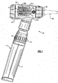
- the otoscope herein labeled 10 includes a cylindrical handle portion 14 that contains a set of batteries (not shown) that are retained within an interior battery compartment (not shown), the handle portion having a bottom portion 17 that is preferably removable in order to permit the exchange of batteries.
- the handle portion 14 permits the instrument 10 to be hand-held and includes a top portion that is sized to accommodate an instrument head 18 which is fitted thereto.
- the instrument head 18 is substantially hollow so as to accommodate an insufflation port 28, the head being defined by a proximal end 22 and an opposing distal end 26 having an axisymmetric distal insertion portion 29, Fig. 6 .
- the handle portion 14 further includes an actuable button 23, disposed above the bottom portion 17, that is used to power up the instrument as well as a rheostat 25 that is used to selectively adjust the illumination output of an illumination assembly that is contained in a necked or throat portion of the instrument head 18. It should be noted that each of the above features relating to the handle portion 14 are commonly known in the field and require no further explanation with regard to the present invention. '
- Figs. 2-5 Before referring more specifically to a more detailed description of the remainder of the herein described otoscopic instrument 10, the following discussion refers to Figs. 2-5 and more specifically to a preferred disposable speculum tip element 40 that is releasably mounted in overlaying relation onto the distal axisymmetric insertion portion 29 of the instrument 10.
- the tip element 40 is made preferably from a moldable plastic material, such as polypropylene, and is defined by a substantially axisymmetric configuration including a pair of open ends, namely a narrowed distal end 44 that tapers outwardly to a wider proximal end 48.
- the proximal end 22 also contains a number of non-axisymmetric features, discussed in greater detail below.
- the tip element 40 shown in Figs. 2-5 represents an Aadult-sized@ tip; that is, a tip element that is used for insertion into the ear of adult patients, though each tip element, regardless of the intended patient, commonly includes a number of engagement features, both external and internal, that permit the tip element 40 to be attached to the otoscope and more particularly to the distal axisymmetric insertion portion 29, Fig. 6 . It will be readily understood that the tips can be made with varying sizes, depending on the patient.
- the present tip elements 40 each include a larger distal aperture and can comfortably extend a greater distance into the ear canal of a patient than any previously known disposable tip element of its aperture size.
- a typical tip element has critical dimensions based on the anatomy of the ear canal and on the conical construction of the distal axisymmetric insertion portion 29 of the instrument 10. Increasing both the inner diameter of the distal end of the tip element 40 and the length of that portion of the tip element insertable into the ear permit a better access to and view of the tympanic membrane.
- a comparison between adult-sized tip elements 40 and pediatric (child) tip elements 40A made in accordance with present invention is provided with previously known tip elements 40', 40A' of the same types as herein represented in Fig. 15 .
- each tip element 40, 40', 40A, 40A' includes a pair of surfaces; a first surface represented from the proximal end of each tip element to an intermediate interface, indicated as-I-, needed to accommodate the cone of the distal axisymmetric insertion portion 29 of the otoscope; and a second conical surface-that extends from the intermediate interface -I- to the distal tip opening.
- the present tip elements 40, 40A are each substantially lengthened beyond the intermediate interface -I-, therefore permitting the tip element to be extended a greater distance into the ear canal of the patient.
- the distal tip aperture of each tip element 40,40A is widened as compared with the depicted previous tip designs 40', 40A'.
- each tip element 40 regardless of the intended patient (e.g., pediatric, adult, etc.,), includes a plurality of external engagement features 52 that are located in relation to the proximal open end 48 of the tip element.
- the intended patient e.g., pediatric, adult, etc.
- three (3) such features 52 equally spaced from one another circumferentially by about 120 degrees, are provided, though the actual number of engagement features provided can easily be varied.
- Each of the external engagement features 52 extends radially from the open proximal end 48 of the tip element 40 and commonly includes a circumferential securing portion 55 and a depending axial portion 54 forming a substantially L-shape, the circumferential securing portion 55 having a plurality of teeth 56 that are located on an engagement surface thereof. Additionally, the circumferential securing portion 55 is substantially wedge-shaped, the portion having a maximum thickness at the interface with the depending axial portion 54 and a tapered minimum thickness at an opposing end, thereby forming the ramped engagement surface.
- the depending axial portions 54 facilitate stacking of a plurality of tip elements 40, as well as provide, a grip surface when attaching the tip elements to the otoscope.
- the interior surface 60 of the herein described tip element 40 is polished to improve light transmissibility and further preferably includes an angled interior protrusion 64 that is located near the proximal tip opening 44.
- the tip element 40 also includes an interior annular sealing ring 70, which is provided to assist in sealing the tip element to a conical portion of the distal axisymmetric insertion portion 29 of the instrument head 18, preferably for insufflating purposes.
- the instrument head 18 retains a number of components, including the above-described disposable tip element 40 that is mounted in overlaying relation onto the distal axisymmetric insertion portion 29 and to an actuator mechanism, also described in greater detail in a later portion of this description that permits releasable attachment/disengagement of the tip element 40 to and from the instrument 10.
- the above instrument 10 can be used for pneumatic otoscopy as is known through a hose connection 272, Fig. 7 , partially shown, to the insufflation port 28, Fig. 7 , the hose connection extending to a pneumatic supply (not shown) as is commonly known.
- an imaging train that includes a predetermined number of optical elements, most of which are disposed within an open-ended tubular member 80.
- the tubular member 80 has a variable diameter that is defined herein by three axial sections, each axial section having a different interior diameter.
- the first axial section 84 of the tubular member 80 is defined by an initial diameter at the distal end thereof, and is sized for retaining an objective distal or front lens 96 and a lens 100, respectively, each of these lenses being disposed in adjacent relation to one another to form a doublet.
- the lenses 96 and 100 are mounted adjacently to one another, with the objective distal lens 96 partially extending outwardly from the distal most opening of the tubular member 80.
- the second axial section 88 of the tubular member 80 is defined, according to this embodiment, by a second interior diameter that is larger than the diameter of the first axial section 84, the second section linking an adjacent third section 92 that contains a first relay lens 104, an aperture stop 108, and a second relay lens 112, respectively, each of these elements being appropriately spaced from one another.
- the diameter of the third axial section 92 of the tubular member 80 is larger than either of the diameters of the first and second portions 84, 88 thereof.
- the tubular member 80 is retained within an inner former assembly 116 that is also positioned within the instrument head 18, wherein the first axial portion 84 of the tubular member 80 is sized to fit within the distal axisymmetric insertion portion 29.
- the inner former assembly 116 provides support for the tubular member 80 and further provides means for a plurality of extending optical fibers (not shown) from an illumination assembly 124. Referring to Fig.
- the illumination assembly 124 is fitted within a necked or throat portion of the instrument head 18, the illumination assembly comprising a miniature incandescent lamp 128, the lamp being mounted within a base 136 and connected thereto via a lamp retainer 140, each of the above being held within a cylindrical sleeve member 144.
- a bumper guard 146 is placed onto the top of the lamp 128 in order to protect the lens envelope.
- the first axial portion 84 of the tubular member 80 is fitted within the interior of the distal axisymmetric insertion portion 29 such that the distal objective lens 96 is proximate the distal opening thereof, as shown in Fig. 6 , the tubular member and surrounding inner former assembly 116 being placed through an opening in the instrument head interior that is sized for accommodating same.
- the tubular member 80 is sealed to the proximal end of the inner former assembly 116 using a suitable adhesive, wherein a portion of the third axial section 92 of the tubular member extends therefrom. The seal, shown as 150 in Fig.
- insufflation port 28 must be proximal (e.g., behind) the insufflation port 28 in order to permit insufflation to be achieved, such as through a hose connection 272, partially shown in Fig. 7 , to a pneumatic supply.
- air entering the insufflation port 28 would flow forward (e.g., toward the insertion portion and the distal tip) meaning that the seal must be toward the proximal end beyond the insufflation port.
- An eyepiece mechanism 160 is retained at the proximal end 48 of the instrument head 18, the mechanism including a substantially cylindrical lens carrier member 164 having a set of external threads 168 that are disposed adjacent to a square distal end 172 thereof.
- the square distal end 172 of the lens carrier member 164 is sized to be fitted into a corresponding opening 180, Fig. 7 , provided within the interior of the instrument head 18 that retains the lens carrier member 164 and prevents the member from rotational movement.
- a tubular lens retainer member 176 is fixedly attached to the lens carrier member 164 by means of corresponding threaded portions 186, 184 on the interior distal end of the lens retainer member 176 and the exterior of the proximal end of the lens carrier member 164, respectively.
- the lens retainer member 176 includes an interior that is sized for receiving a pair of optical lenses 190, 194, that, when the lens retainer member and the lens carrier member are assembled to the instrument head 18, are aligned along the optical axis 27, Fig. 7 , on which the optical elements 96, 100, 104, 112 of the imaging train are also aligned.
- the eyepiece mechanism 160 further includes a wave spring 192 and a lens retainer 196, each being disposed between the lens 190 and the lens carrier member 164.
- a spacer 195 is disposed between the lenses 194, 190 and an O-ring 199 is used to seal the lens 194 with the lens carrier member 176.
- the external threads 168 of the lens carrier member 164 engage with a set of corresponding threads 207 that are provided on the interior surface of a cylindrical focusing sleeve member 200 that is fitted thereupon in overlaying relation.
- the focusing sleeve member 200 has an axial length extending so as to project from the proximal end 48 of the instrument head 18 when the sleeve member is attached.
- a soft grippable elastomeric cover 202 overlays an axial portion of the sleeve member 200, the cover being mounted to rotate along with the sleeve member to an end of travel as determined by protrusion 203.
- a ball and compression spring 204, 206 shown only in Fig.
- a focusing knob 208 is snap fitted onto the extending proximal end of the focussing sleeve member 200.
- the focusing knob 208 includes a center opening 212, permitting the user/practitioner to view a target along the aligned optical axis 27, as does each of the focusing sleeve member 200 and the lens retainer member 176, respectively, and permitting selective axial adjustment of the eyepiece mechanism 160, Fig.
- the lens retainer member 176 is adjusted relative to the lens carrier member 164. This adjustment permits creating a factory setting, for example, for humans at a certain focal length, and a different factory setting for example, for veterinary uses having a longer default focus position, wherein the sleeve member simply adjusts either above or below this position.
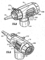
- the instrument head 18 further includes a pair of windows 21, Figs. 8, 9 , that are formed on opposing lateral sides thereof, wherein axial portions of the soft grippable elastomeric cover 202 to the sleeve member 200 are accessible to a user in addition to the focusing knob 208, as shown, for example, in Figs. 8 and 9 .
- This mechanism includes a tip element retainer member 240 that is stationarily attached to the distal end of the instrument head 18, the retainer including a plurality of circumferentially spaced slots 242.
- the retainer including a plurality of circumferentially spaced slots 242.
- three slots 242 are provided, in which two of the slots include circumferential ramped surfaces 244.
- Each of the ramped surfaces 244 includes a set of teeth for engaging with the teeth 56 that are provided on the external engagement tabs 52 of the tip element 40.
- the tip actuator mechanism further includes a rotatable actuator knob 252 that is biased by means of a spring 256, the spring having an axial first end 260 that passes through a slot 264 in the actuator knob 252 to a hole 268 provided in the retainer member 240. The remaining end 269 of the spring 256 fitted within a slot 270 that is formed on the actuator knob 252.
- the retainer member 240 attaches to a front facing surface of the rotatable actuator knob 252, the actuator knob further including a pin 254 that extends from the front facing surface into that slot 242 in the retainer member not having the circumferential ramping surfaces 244.
- an otoscopic tip element 40 as described above, is attached onto the distal end of the instrument head 18 and more specifically in overlaying relation to the distal axisymmetric insertion portion 29, the circumferential securing portions 55 of each of the external engagement features 52 being fitted into the circumferential slots 242 that are provided in the tip element retainer member 240.
- the tip element 40 is then twisted, in this example, in a clockwise fashion, so as to engage the teeth 56 of two of the wedge-like engagement features 52 with the corresponding ramped surfaces 244 of the tip element retainer member 240, thereby providing positive engagement and providing tactile feedback to the user when attaching the tip element 40 to the instrument 10.
- the actuator knob 252 is rotated in a counter-clockwise direction as denoted preferably by an indicator 261 located on the exterior of the actuator knob 252. This causes rotational movement of the knob 252 relative to the stationary tip element retainer member 240 and further causes a front face pin 254 to move that slot 242 not having a ramped surface 244, driving the tip element 40 rotationally from the slots of the retainer member 240, releasing the tip element.
- the design of the herein described tip element 40 is fairly universal; that is, the tip element is designed not only to fit the herein described instrument 10, but a number of already existing otoscopes, such as those employing bayonet-type attachment scheme as described by U.S. Patent No. 3,698,387 , and ejector-type mechanism as described be U.S. Patent No. 4,366,811 the entire contents of each herein being incorporated by reference.
- the use of the focusing mechanism permits relative movement of the optics of the eyepiece mechanism 160 relative to the imaging train of the instrument 10.
- the focusing sleeve member 200 and the soft grippable elastomeric cover piece 202 are each permitted to rotate about the optical axis 27, while the lens carrier member 164 and attached lens retainer member 176 are caused only to translate linearly due to the rotationally fixed connection with the instruments head 18.
- the remainder of the optical imaging train, disposed within the tubular member 80, including front objective lens 96 is stationary, and therefore relative movement is achieved, permitting focus adjustment to take place.
- the biased engagement of the ball by the compression spring into the depression of the focusing sleeve member 200 provides an indication of a predetermined fixed focus position (a preset position or distance between the eyepiece optics and the optics of the remainder of the stationary imaging train within tubular member 80) as sensed by the user/practitioner.
- Indication of this preset or other focus position can be achieved by means of a visual indicator 209, provided on the exterior of the grippable elastomeric cover 202, portions of the cover being accessible through the windows 21 formed on lateral sides of the instrument head 18 to enable selective rotary movement of the focusing mechanism by mean of the soft grippable cover 202 in lieu of the focusing knob 208.
- a scale of markers 213 are formed on edge portions of the instrument head adjacent the windows 21 including a preset focus position marker 215 that can be aligned with the visual indicator 209 which, in combination with the detent, further indicates the preferred nominal focusing position of the instrument 10.
- the overall length of the entire imaging system (e.g., the distance between the most distal and proximal optical surfaces including the eyepiece optics) is approximately 77.60 mm
- the magnification is 1.63 X when the tympanic membrane is located at a working distance of approximately 10 mm from the open distal end 44 of the speculum tip element 40
- the depth of field is approximately 3-5 mm.
- the nominal eye relief is approximately 21.5 mm.
- the aperture stop 108 is optically conjugate to both the entrance pupil 8 and the exit pupil 9 of the entire optical system.
- the axial location and the size of the entrance pupil 8 are critical in achieving an unobstructed view of the entire tympanic membrane, shown schematically in Fig. 19 as 6. If the entrance pupil 8, which is located distally relative to lens 96, is too close to that lens, there is excessive obstruction of rays emerging from the upper edge of the tympanic membrane 6 by the end of the tip element 40.
- the entrance pupil 8 is located in close proximity to the objective lens doublet (lenses 96 and 100), such as to achieve the optimal view of the tympanic membrane 6 with minimal ray obstruction. Similar considerations apply to the physical size of the aperture stop 108.
- the exit pupil 9 is located approximately 21.5 mm proximal to the most proximal optical surface of lens 194. This distance provides: a) optimal image stability in relation to lateral movement of the user's eye during an ear examination; b) optimal viewing of the tympanic membrane 6 with minimal ray obstruction; and c) the ability to accommodate a large range of spectacle lenses.
- This exit pupil location relative to lenses 190 and 194 is constant regardless of the position of the focusing mechanism.
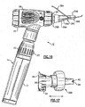
- optical system described herein can easily be expanded to video/imager human otoscopy by adding an electronic imager assembly 304 onto the proximal end of the otoscope, as shown in Fig. 20 .
- the herein described instrument can similarly be used for optical or video/imager based veterinary otoscopy.
- Selective focusing travel of the lenses 190 and 194 of the eyepiece mechanism is such as to give the user the ability to achieve a close-up view (important in infant ear examinations) and a distant view (important in throat and nasal examinations).
- the working distance between the tympanic membrane 6 and the first optical surface of the distal lens 96 is optimized according to this embodiment to fall around 27 mm; this latter dimension is clinically important because it provides the correct setup between inserting the otoscope too deeply into the ear canal.
- the herein described optical system produces an erect image of the tympanic membrane to the user at the viewing means.
- the imaging train substantially places the objective doublet 96, 100 within the ear at the time of examination, since this optical element is located in the distalmost portion of the instrument head 18, and much closer to the tympanic membrane than any typical otoscope.
- a greater (e.g., wider) field of view is achieved, i.e., an area larger than that of the tympanic membrane can be viewed by the user in an operative position of the instrument.
- the entrance pupil location enables an unobstructed view of a typical 7 mm adult tympanic membrane for working distances greater than or about 27 mm, wherein the working distance is defined as the spacing separating the tympanic membrane from the distal surface of the lens 96 or approximately, according to this embodiment, about 9.5 mm from the tympanic membrane to the distal end of the tip element 40.
- the working distance is defined as the spacing separating the tympanic membrane from the distal surface of the lens 96 or approximately, according to this embodiment, about 9.5 mm from the tympanic membrane to the distal end of the tip element 40.
- an appropriate tradeoff is achieved between magnification, field of view, working distance, eye relief and focusing range.
- the latter parameter is additionally critical so as to allow the instrument to be further used, for example, for examinations of the throat and/or nose of the patient.
- an instrumentation tip 280 and a curette 284 are herein described dealing with the above-stated problem, which allows for significantly better instrument insertion while still viewing through the optics of an otoscope 10, such as that previously described, for example.
- the instrumentation tip 280 according to this embodiment is essentially a cage-like member 290 that extends the tip contacting the patient away from the otoscope, leaving a large open area into which the burette 284 can be inserted and manipulated. It should be understood that the tip that contacts the patient can take a variety of shapes and sizes as can the cage distance and support structure.
- the cage-like member 290 is defined by three legs 294 extending between a distal ear insertion portion 298 and a proximal otoscope attachment portion 299, the entirety of the cage-like member being approximately one inch in length.
- the curette 284 is ideally curved to maximize the ability to manipulate it within the defined open areas between the legs 294.
- Alternative configurations where some or the entire cage is reusable or integrally attached to the scope should be readily apparent to one of sufficient skill in the field.
- the advantage of a fully disposable version is that the nature of instrumentation implies that some foreign body has been removed from the ear which increases the exposure and risk of cross contamination.
- the otoscope attachment portion 299 preferably includes external engagement features, such as shown in Figs. 2-5 , an or including an internal bayonet, depending on the tip attachment mechanism of the otoscope used therewith.
- a further problem, with disposable otoscope tips is that they do not seal well to the majority of most patient's ears. Further, soft overmold tip versions seal relatively well, but prevent insertion within the ear beyond the depth at which the elastomer interferes with the ear. Therefore, although the tips achieve an effective seal, they prevent or impede the visualization that is essential during insufflation. It serves no practical purpose to seal and insufflate if the tympanic membrane cannot be viewed during this process, as the movement (or lack thereof) creates the basis for diagnosis.
- an elastomeric seal accessory 300 is provided according to one embodiment that slides onto the exterior of a disposable tip element, such as those previously described in Figs. 2-5 , or other version haying a substantially conical body.
- This elastomeric seal accessory 300 provides a good seal to the patient ear and is adjustable in its axial position on the tip 40. Therefore, the tip can be set for "deeper” insertion or shallow insertion so that both the seal as well as the proper insertion depth for visualization can be achieved.
- This seal accessory 300 is preferably compliant enough that it is set at the distal end of the tip and "pushes in” as the practitioner inserts the tip into the ear canal (not shown).
- the geometry of the elastomeric seal accessory 300 itself also creates an advantage since it is mushroom shaped in the present embodiment, allowing the accessory to collapse in order to seal with a variety of ear canal sizes.
Landscapes
- Health & Medical Sciences (AREA)
- Life Sciences & Earth Sciences (AREA)
- Surgery (AREA)
- Biomedical Technology (AREA)
- Medical Informatics (AREA)
- Optics & Photonics (AREA)
- Pathology (AREA)
- Radiology & Medical Imaging (AREA)
- Biophysics (AREA)
- Engineering & Computer Science (AREA)
- Physics & Mathematics (AREA)
- Heart & Thoracic Surgery (AREA)
- Nuclear Medicine, Radiotherapy & Molecular Imaging (AREA)
- Molecular Biology (AREA)
- Animal Behavior & Ethology (AREA)
- General Health & Medical Sciences (AREA)
- Public Health (AREA)
- Veterinary Medicine (AREA)
- Endoscopes (AREA)
- Measuring And Recording Apparatus For Diagnosis (AREA)
Applications Claiming Priority (5)
| Application Number | Priority Date | Filing Date | Title |
|---|---|---|---|
| US49056603P | 2003-07-28 | 2003-07-28 | |
| US50747303P | 2003-09-30 | 2003-09-30 | |
| US54385804P | 2004-02-11 | 2004-02-11 | |
| US10/897,455 US7354399B2 (en) | 2003-07-28 | 2004-07-23 | Otoscopic tip element and related method of use |
| PCT/US2004/024008 WO2005016117A2 (en) | 2003-07-28 | 2004-07-26 | Otoscopic tip element and related method of use |
Publications (2)
| Publication Number | Publication Date |
|---|---|
| EP1659923A2 EP1659923A2 (en) | 2006-05-31 |
| EP1659923B1 true EP1659923B1 (en) | 2016-02-24 |
Family
ID=34682335
Family Applications (1)
| Application Number | Title | Priority Date | Filing Date |
|---|---|---|---|
| EP04786112.5A Expired - Lifetime EP1659923B1 (en) | 2003-07-28 | 2004-07-26 | Otoscopic tip element and related method of use |
Country Status (9)
| Country | Link |
|---|---|
| US (3) | US7354399B2 (https=) |
| EP (1) | EP1659923B1 (https=) |
| JP (1) | JP2007500542A (https=) |
| CN (1) | CN1984599B (https=) |
| AU (1) | AU2004264876B2 (https=) |
| CA (1) | CA2533826C (https=) |
| IL (1) | IL173279A (https=) |
| NZ (1) | NZ544953A (https=) |
| WO (1) | WO2005016117A2 (https=) |
Cited By (1)
| Publication number | Priority date | Publication date | Assignee | Title |
|---|---|---|---|---|
| US10758113B2 (en) | 2016-03-08 | 2020-09-01 | Zumax Medical Co., Ltd | Medical otoscope |
Families Citing this family (87)
| Publication number | Priority date | Publication date | Assignee | Title |
|---|---|---|---|---|
| US20060120432A1 (en) * | 2003-01-06 | 2006-06-08 | Loren Lantz | Tympanic thermometer with ejection mechanism |
| US8066634B2 (en) * | 2003-07-28 | 2011-11-29 | Welch Allyn, Inc. | Digital otoscope |
| US7354399B2 (en) * | 2003-07-28 | 2008-04-08 | Welch Allyn, Inc. | Otoscopic tip element and related method of use |
| USD566838S1 (en) * | 2004-02-04 | 2008-04-15 | Welch Allyn, Inc. | Otoscopic instrument head |
| USD615650S1 (en) | 2006-03-10 | 2010-05-11 | Welch Allyn, Inc. | Veterinary otoscopic tip element |
| US20070248141A1 (en) * | 2006-04-21 | 2007-10-25 | Sherwood Services Ag | Infrared thermometer and probe cover thereof |
| DE102006058358A1 (de) * | 2006-12-05 | 2008-06-12 | Carl Zeiss Surgical Gmbh | Kameraadapter mit Kamerahalterung und Optikadapter |
| US8033670B2 (en) * | 2006-12-29 | 2011-10-11 | Cognex Corporation | Manually adjustable ruggedized focus mechanism |
| US7665893B2 (en) * | 2007-02-16 | 2010-02-23 | Parker Laboratories, Inc. | Protective cover set for a medical probe |
| USD598545S1 (en) * | 2007-04-03 | 2009-08-18 | Welch Allyn, Inc. | Digital otoscope |
| TW200921063A (en) * | 2007-11-09 | 2009-05-16 | Actherm Inc | Probe cover for ear thermometer and manufacturing method thereof |
| US8657491B2 (en) | 2007-11-09 | 2014-02-25 | Actherm Inc. | Detachable probe cover for ear thermometer and manufacturing method thereof |
| US7813889B2 (en) * | 2008-01-16 | 2010-10-12 | Welch Allyn, Inc. | Guiding IR temperature measuring device with probe cover |
| US20090206264A1 (en) * | 2008-02-14 | 2009-08-20 | Robert Christopher Twiney | Infra-red temperature sensor |
| US7882928B2 (en) * | 2008-06-26 | 2011-02-08 | Welch Allyn, Inc. | Acoustic measurement tip |
| US20100108706A1 (en) * | 2008-11-05 | 2010-05-06 | Kleen Test Products Inc | Closure mechanism for wipe dispenser |
| US8155361B2 (en) * | 2008-12-04 | 2012-04-10 | Insound Medical, Inc. | Insertion device for deep-in-the-canal hearing devices |
| JP5431500B2 (ja) | 2008-12-29 | 2014-03-05 | カズ ヨーロッパ エスエー | マッチング機構を有する医療用温度計用プローブカバー |
| USD685482S1 (en) | 2009-04-09 | 2013-07-02 | Welch Allyn, Inc. | Cover for a probe or the like |
| US8231271B2 (en) * | 2009-04-09 | 2012-07-31 | Welch Allyn, Inc. | IR thermometry probe cover |
| US12492949B2 (en) | 2009-04-09 | 2025-12-09 | Welch Allyn, Inc. | IR thermometry probe cover |
| US8876373B2 (en) | 2009-04-09 | 2014-11-04 | Welch Allyn, Inc. | IR thermometry probe cover |
| USD787683S1 (en) | 2009-04-09 | 2017-05-23 | Welch Allyn, Inc. | Cover for a probe |
| USD618346S1 (en) * | 2009-06-16 | 2010-06-22 | Sisko Michael A | Data capture and recording device |
| US8062216B2 (en) * | 2009-07-14 | 2011-11-22 | Puthalath Koroth Raghuprasad | Otoscope with attachable ear wax removal device |
| US8517603B2 (en) * | 2009-10-05 | 2013-08-27 | Kaz Usa, Inc. | Multi-site attachments for ear thermometers |
| US20110137118A1 (en) * | 2009-10-06 | 2011-06-09 | Apple Biomedical, Inc. | Medical inspection device |
| US8226573B2 (en) * | 2009-11-16 | 2012-07-24 | Tyco Healthcare Group Lp | Thermometer probe |
| USD625803S1 (en) * | 2009-12-14 | 2010-10-19 | Conmed Corporation | Surgical collet |
| US20110166421A1 (en) * | 2010-01-01 | 2011-07-07 | Pejman Katiraei | Enhanced Otoscope Cover |
| US20110202121A1 (en) * | 2010-02-16 | 2011-08-18 | Shin-Heng Wen | Electrical nerve stimulator |
| CN103079457A (zh) * | 2010-06-01 | 2013-05-01 | 小利兰斯坦福大学理事会 | 用于照明身体孔道的系统 |
| DE202011050045U1 (de) * | 2011-05-05 | 2011-07-28 | Kirchner & Wilhelm Gmbh + Co. Kg | Instrumentenhandgriff für eine medizinische Diagnostikleuchte und medizinische Diagnostikleuchte |
| WO2013071153A1 (en) | 2011-11-09 | 2013-05-16 | Welch Allyn, Inc. | Digital-based medical devices |
| US20130150675A1 (en) * | 2011-12-07 | 2013-06-13 | Lillian Folley | Transparent Speculum Apparatus and System |
| US9198560B2 (en) * | 2012-03-19 | 2015-12-01 | Welch Allyn, Inc. | Medical diagnostic instrument |
| DE102012011717A1 (de) | 2012-06-14 | 2013-12-19 | Karl Storz Gmbh & Co. Kg | Optisches Instrument |
| US9636449B2 (en) * | 2012-06-18 | 2017-05-02 | Ketan C. Mehta | Rinsing assembly |
| US9307912B2 (en) | 2012-08-08 | 2016-04-12 | Welch Allyn, Inc. | Temperature measurement system |
| US8452382B1 (en) * | 2012-09-21 | 2013-05-28 | Brooklands Inc. | Non-contact thermometer sensing a carotid artery |
| DE102012223691A1 (de) | 2012-12-19 | 2014-06-26 | Heine Optotechnik Gmbh & Co Kg | Otoskop mit abwerfbarem Ohrtrichter |
| JP6489652B2 (ja) | 2013-02-04 | 2019-03-27 | ヘレン オブ トロイ リミテッド | 耳鏡装置 |
| KR20160005675A (ko) * | 2013-02-04 | 2016-01-15 | 헬렌 오브 트로이 리미티드 | 검이경 |
| CN105163643B (zh) | 2013-02-04 | 2017-08-08 | 特洛伊海伦有限公司 | 耳镜 |
| KR20160005677A (ko) | 2013-02-04 | 2016-01-15 | 헬렌 오브 트로이 리미티드 | 피험자의 귀의 상태를 결정하는 방법 및 귀 검사 장치 |
| SG11201505465UA (en) * | 2013-02-04 | 2015-08-28 | Helen Of Troy Ltd | Otoscope |
| US10078226B2 (en) | 2013-10-14 | 2018-09-18 | Welch Allyn, Inc. | Portable eye viewing device enabled for enhanced field of view |
| US10213098B2 (en) | 2013-11-08 | 2019-02-26 | Welch Allyn, Inc. | Laser configured otoscope |
| US10092175B2 (en) | 2014-02-12 | 2018-10-09 | Welch Allyn, Inc. | Eye viewing device enabled for performing ear examinations and adapter |
| USD739535S1 (en) * | 2014-05-14 | 2015-09-22 | Carl Zeiss Meditee AG | Combined ophthalmic instrument and ophthalmic instrument stand |
| USD756517S1 (en) * | 2014-07-02 | 2016-05-17 | Comprehensive Telemedicine | Multi-purpose medical imaging device support apparatus |
| US9675246B2 (en) * | 2014-09-15 | 2017-06-13 | Welch Allyn, Inc. | Borescopic optical system for medical diagnostic instruments and medical diagnostic instruments having interlocking assembly features |
| CN104323757A (zh) * | 2014-11-13 | 2015-02-04 | 王卫东 | 用于具有闪光灯和摄像头的便携智能设备的内窥镜 |
| US10952601B2 (en) | 2015-05-08 | 2021-03-23 | Photonicare, Inc. | Otoscope tip and methods of use |
| WO2016182999A1 (en) | 2015-05-08 | 2016-11-17 | Photonicare, Inc. | Otoscope tip and methods of use |
| US20160374546A1 (en) | 2015-06-25 | 2016-12-29 | Wisconsin Alumni Research Foundation | Otoscope Providing Multi-Directional Illumination |
| US11576567B2 (en) | 2015-06-25 | 2023-02-14 | Wisconsin Alumni Research Foundation | Otoscope providing low obstruction electronic display |
| US12114958B2 (en) * | 2015-09-08 | 2024-10-15 | Medwand Solutions, Inc. | Integrated medical device and home based system to measure and report vital patient physiological data via telemedicine |
| US10765309B1 (en) | 2015-11-03 | 2020-09-08 | Ziad A. Alsaifi | Multifunctional otoscope |
| US11096627B2 (en) | 2016-04-25 | 2021-08-24 | Welch Allyn, Inc. | Medical examination system enabling interchangeable instrument operating modes |
| US9867738B2 (en) | 2016-05-09 | 2018-01-16 | John J. Lenig | Ear wax remover and cleaner |
| US10357161B1 (en) | 2017-05-31 | 2019-07-23 | Otonexus Medical Technologies, Inc. | Infrared otoscope for characterization of effusion |
| US10568515B2 (en) * | 2016-06-21 | 2020-02-25 | Otonexus Medical Technologies, Inc. | Optical coherence tomography device for otitis media |
| GB2569079B (en) * | 2016-09-16 | 2022-02-16 | Throat Scope Pty Ltd | An otoscope |
| US10667953B2 (en) | 2017-08-08 | 2020-06-02 | Larry A. Hendricks | Instrument for examination of ear and removal of ear wax |
| JP6630330B2 (ja) * | 2017-10-04 | 2020-01-15 | 国立大学法人鳥取大学 | 耳鏡 |
| GB2569325B (en) | 2017-12-13 | 2020-05-06 | Imperial Innovations Ltd | Ear examination apparatus |
| USD894383S1 (en) | 2017-12-28 | 2020-08-25 | Wisconsin Alumni Research Foundation | Otoscope |
| US11147441B2 (en) | 2018-01-16 | 2021-10-19 | Welch Allyn, Inc. | Physical assessment device |
| WO2019191818A1 (en) * | 2018-04-05 | 2019-10-10 | Rusoke Dierich Olaf | Medical device, accessories for use therewith, and methods of use |
| WO2019226701A1 (en) * | 2018-05-22 | 2019-11-28 | The Regents Of The University Of California | Light-emitting diode based diffuse optical spectroscopy tool |
| JP7697881B2 (ja) * | 2018-10-03 | 2025-06-24 | オトネクサス メディカル テクノロジーズ, インコーポレイテッド | 超音波および光学照明を用いた膜特性評価のための方法およびデバイス |
| CN113423349A (zh) * | 2019-02-08 | 2021-09-21 | 回弹治疗公司 | 带有照明的套管系统 |
| US10925478B2 (en) * | 2019-02-21 | 2021-02-23 | Wisconsin Alumni Research Foundation | Disposable speculum for digital otoscope |
| US11399709B2 (en) | 2019-03-18 | 2022-08-02 | Welch Allyn, Inc. | Speculum tip element and method for optimizing light efficiency/emission of a speculum tip element |
| USD897184S1 (en) | 2019-06-05 | 2020-09-29 | Welch Allyn, Inc. | Handle |
| USD897186S1 (en) | 2019-06-05 | 2020-09-29 | Welch Allyn, Inc. | Handle |
| USD897185S1 (en) | 2019-06-05 | 2020-09-29 | Welch Allyn, Inc. | Handle |
| US20210038082A1 (en) * | 2019-08-07 | 2021-02-11 | Deanna Lynn Vicera | Handheld pet diagnostic device and methods of use |
| CN112729549B (zh) * | 2019-10-14 | 2021-10-22 | 百略医学科技股份有限公司 | 具耳套弹出装置的耳温枪 |
| US11642011B1 (en) | 2020-02-27 | 2023-05-09 | Yingjie Sun | Protective cover apparatus for an otoscope |
| USD966508S1 (en) * | 2020-04-30 | 2022-10-11 | Yingjie Sun | Otoscope protective cap |
| USD967418S1 (en) * | 2020-05-01 | 2022-10-18 | Yingjie Sun | Double layer otoscope protective cap |
| US11497391B2 (en) * | 2020-06-24 | 2022-11-15 | Timothy F. Kelley, MD Inc. | Jointed speculum |
| US11944275B2 (en) * | 2021-05-22 | 2024-04-02 | ScopeBug, Inc. | System and device for viewing of a body portion |
| CN115813437B (zh) * | 2022-11-24 | 2024-11-05 | 深圳英美达医疗技术有限公司 | 超声探头及具有该超声探头的超声内窥镜 |
| CN117883033A (zh) * | 2024-02-05 | 2024-04-16 | 广州立景创新科技有限公司 | 耳镜 |
Family Cites Families (74)
| Publication number | Priority date | Publication date | Assignee | Title |
|---|---|---|---|---|
| US3110304A (en) * | 1962-06-08 | 1963-11-12 | Berhard H Hartman | Ear speculum and otoscope |
| US3374791A (en) * | 1965-07-21 | 1968-03-26 | Westerman Samuel Thomas | Ear speculum |
| US3698387A (en) * | 1969-10-07 | 1972-10-17 | Welch Allyn Inc | Otoscope construction |
| US3815584A (en) * | 1972-11-07 | 1974-06-11 | Bio Analytical Labor Inc | Speculum barrel and retainer ring assembly |
| US3840004A (en) * | 1973-01-26 | 1974-10-08 | Heine Optotech Kg | Otoscope with disposable speculum |
| US3929018A (en) * | 1974-05-06 | 1975-12-30 | American Med Electronics | Probe system |
| DE3009876C2 (de) * | 1980-03-14 | 1985-07-18 | Rudolf Riester Gmbh & Co Kg, Fabrik Med. Apparate, 7455 Jungingen | Otoskop mit Auswerfereinrichtung |
| US4380998A (en) * | 1981-01-05 | 1983-04-26 | Welch Allyn, Inc. | Soft tip speculum |
| US4488701A (en) * | 1982-06-10 | 1984-12-18 | Automotive Products Plc. | Quick connect cylinder mount structure |
| US4454370A (en) * | 1982-09-07 | 1984-06-12 | Wahl Instruments, Inc. | Thermocouple surface probe |
| US4567924A (en) * | 1983-02-25 | 1986-02-04 | Brown Albert W | Aircraft under-wing fueling nozzle system |
| DE3414730A1 (de) * | 1984-04-18 | 1985-10-31 | Rudolf Riester Gmbh & Co Kg, Fabrik Med. Apparate, 7455 Jungingen | Otoskop und verfahren zu seiner herstellung |
| US4662360A (en) * | 1984-10-23 | 1987-05-05 | Intelligent Medical Systems, Inc. | Disposable speculum |
| US4702537A (en) * | 1985-05-03 | 1987-10-27 | Matrix Science Corporation | Quick-disconnect electrical connector coupling assembly for use with bayonet pin coupling system |
| US4784149A (en) * | 1986-01-13 | 1988-11-15 | Optical Sensors, Inc. | Infrared thermometer with automatic calibration |
| US4785796A (en) * | 1986-09-12 | 1988-11-22 | Mattson Philip D | Otoscope and flexible, disposable curette for use therewith |
| US5176630A (en) * | 1988-09-22 | 1993-01-05 | Aegis Medical, Inc. | Rectal insertion device and control valve means therefor |
| US4997419A (en) * | 1989-06-01 | 1991-03-05 | Edward Weck Incoporated | Laparoscopy cannula |
| US5066142A (en) * | 1990-03-08 | 1991-11-19 | Ivac Corporation | Protective apparatus for a biomedical probe |
| EP0445783B1 (en) * | 1990-03-08 | 1996-02-07 | Ivac Corporation | Thermally isolated probe |
| US5487607A (en) * | 1992-04-08 | 1996-01-30 | Omron Corporation | Radiation clinical thermometer |
| US5363839A (en) * | 1992-09-21 | 1994-11-15 | Jedmed Instrument Company | Video otoscope |
| CA2133687C (en) * | 1992-10-09 | 2007-03-27 | David T. Green | Surgical clip applier |
| US5295975A (en) * | 1992-10-28 | 1994-03-22 | Lockwood Jr Hanford N | Hypodermic needle safety device with sliding outer cover |
| US5624453A (en) * | 1993-02-23 | 1997-04-29 | Wilson-Cook Medical, Inc. | Endoscopic ligating instrument |
| US5411032A (en) * | 1993-06-18 | 1995-05-02 | Infra-Temp Inc. | Electronic thermometer probe cover |
| US5390663A (en) * | 1993-12-23 | 1995-02-21 | Schaefer; Nicholas E. | Canal obstruction remover |
| US5893833A (en) * | 1995-06-06 | 1999-04-13 | Exergen Corporation | Axillary infrared thermometer and cover therefor |
| US5765610A (en) * | 1996-01-29 | 1998-06-16 | Brown; Albert W. | Aircraft fueling nozzle having improved lock pins |
| GB9603255D0 (en) * | 1996-02-16 | 1996-04-17 | Shaikho Ahmed A | Sterilizing apparatus |
| US6099537A (en) * | 1996-02-26 | 2000-08-08 | Olympus Optical Co., Ltd. | Medical treatment instrument |
| US5795067A (en) * | 1996-05-07 | 1998-08-18 | Thermoscan, Inc. | Enhanced protective lens cover for an infrared thermometer |
| US5842971A (en) * | 1996-05-22 | 1998-12-01 | Yoon; Inbae | Optical endoscopic portals and methods of using the same to establish passages through cavity walls |
| US6554765B1 (en) * | 1996-07-15 | 2003-04-29 | East Giant Limited | Hand held, portable camera with adaptable lens system |
| US6106457A (en) * | 1997-04-04 | 2000-08-22 | Welch Allyn, Inc. | Compact imaging instrument system |
| US6142934A (en) | 1997-04-04 | 2000-11-07 | Welch Allyn, Inc. | Objective lens system for imaging instrument |
| AU7807898A (en) * | 1997-06-03 | 1998-12-21 | Trutek, Inc. | Tympanic thermometer with modular sensing probe |
| US6053875A (en) * | 1998-01-13 | 2000-04-25 | Rosenbaum; Marvin | Removable tip for an acoustic reflectometer |
| US6347243B1 (en) * | 1998-03-05 | 2002-02-12 | Advanced Monitors Corp. | Probe cover for infrared thermometer |
| US6129661A (en) * | 1998-04-09 | 2000-10-10 | Smith & Nephew, Inc. | Endoscopic instrumentation with working channel |
| US6129673A (en) * | 1998-06-08 | 2000-10-10 | Advanced Monitors, Corp. | Infrared thermometer |
| US6224256B1 (en) * | 1998-06-18 | 2001-05-01 | Harry Bala | Cover for medical probe |
| US6511420B1 (en) * | 1998-08-06 | 2003-01-28 | The Johns Hopkins University | Video opto-diagnostic instrument with single-adjustment focus |
| JP3514138B2 (ja) * | 1998-09-29 | 2004-03-31 | テルモ株式会社 | プローブカバー取り外し機構および耳式体温計 |
| US7419467B2 (en) | 1998-11-25 | 2008-09-02 | M3 Electronics, Inc. | Medical inspection device |
| US6155987A (en) * | 1999-02-11 | 2000-12-05 | Scherl; Michael | Assembly for removing ear wax from one's ear canal |
| US6213938B1 (en) * | 1999-05-26 | 2001-04-10 | Health & Technology, Inc. | Disposable otoscope tip stacking system |
| US6190310B1 (en) * | 1999-05-26 | 2001-02-20 | Health & Technology, Inc. | Disposable otoscope tip system |
| DE19929503B4 (de) * | 1999-06-28 | 2008-06-26 | Braun Gmbh | IR-Thermometer für unterschiedliche Messorte |
| DE29911303U1 (de) * | 1999-06-29 | 1999-10-28 | Oriental System Technology Inc., Hsinchu | Meßfühlerabdeckung für tympanales Thermometer |
| US6383133B1 (en) * | 1999-11-09 | 2002-05-07 | Dwight T. Jones | Otoscope kit |
| US20020193665A1 (en) * | 1999-11-09 | 2002-12-19 | Jones Dwight T. | Otoscope kit |
| US6450970B1 (en) * | 1999-11-16 | 2002-09-17 | Ron Mahler | Method and device for diagnosing an inflammatory process |
| US6390671B1 (en) * | 2000-04-28 | 2002-05-21 | K-Jump Health Co., Ltd. | Probe cover with film insert |
| US20020085616A1 (en) * | 2001-01-04 | 2002-07-04 | Mesure Technology Co., Ltd. | Ear thermometer head |
| AU2002219499A1 (en) | 2001-01-19 | 2002-07-30 | Framtidartaekni Ehf. | Hand-held digital imaging diagnostic and operational instrument with wireless transmission data of image |
| US6830347B2 (en) * | 2001-02-14 | 2004-12-14 | Welch Allyn, Inc | Eye viewing device comprising eye cup |
| JP3828436B2 (ja) * | 2001-03-22 | 2006-10-04 | オリンパス株式会社 | バッテリ式内視鏡装置 |
| DE20106011U1 (de) * | 2001-04-05 | 2001-08-09 | Mesure Technology Co., Ltd., San Chung, Taipeh | Thermometer mit auswechselbaren Messköpfen |
| JP3945189B2 (ja) * | 2001-06-01 | 2007-07-18 | オムロンヘルスケア株式会社 | 赤外線体温計 |
| US6549323B1 (en) * | 2001-10-01 | 2003-04-15 | The Boeing Company | Active optical system for phase-shifting desired portions of an incoming optical wavefront |
| US6698625B2 (en) * | 2002-02-11 | 2004-03-02 | Nestec S.A. | Mixing and frothing device and method |
| US7004623B2 (en) * | 2002-03-21 | 2006-02-28 | Jon Nakagawa | Disposable sheath for data logger probe and method for measuring and recording temperature in a closed container |
| ATE468528T1 (de) * | 2003-01-06 | 2010-06-15 | Covidien Ag | Sondenabdeckung für trommelfellthermometer |
| US7037083B2 (en) * | 2003-01-08 | 2006-05-02 | Brooks Automation, Inc. | Radiation shielding coating |
| US6786636B1 (en) * | 2003-07-15 | 2004-09-07 | Norm Pacific Automation Corp. | Mechanism for removing probe cover from a thermometer probe |
| US7399275B2 (en) * | 2003-07-28 | 2008-07-15 | Welch Allyn, Inc. | Otoscope |
| US7354399B2 (en) * | 2003-07-28 | 2008-04-08 | Welch Allyn, Inc. | Otoscopic tip element and related method of use |
| US7017953B2 (en) * | 2003-12-08 | 2006-03-28 | General Motors Corporation | Twist lock assembly |
| US20060020176A1 (en) * | 2004-07-21 | 2006-01-26 | Jonathan Berall | Portable handheld medical diagnostic tool ''Camcorder handle'' |
| US7083330B1 (en) * | 2004-10-19 | 2006-08-01 | Huang Hua Co., Ltd. | Ear thermometer having breakable ear cap |
| TW200709802A (en) * | 2005-09-09 | 2007-03-16 | Radiant Innovation Inc | Ear thermometer with a simple-structure and easy-operation probe-cover detaching mechanism |
| US20080203078A1 (en) * | 2007-02-23 | 2008-08-28 | Michael Carl Huerter | Windshield heater |
| TWI340822B (en) * | 2007-11-15 | 2011-04-21 | Actherm Inc | Probe cover for an ear thermometer, manufacturing method thereof |
-
2004
- 2004-07-23 US US10/897,455 patent/US7354399B2/en not_active Expired - Lifetime
- 2004-07-26 NZ NZ544953A patent/NZ544953A/en unknown
- 2004-07-26 WO PCT/US2004/024008 patent/WO2005016117A2/en not_active Ceased
- 2004-07-26 CA CA2533826A patent/CA2533826C/en not_active Expired - Lifetime
- 2004-07-26 CN CN2004800217624A patent/CN1984599B/zh not_active Expired - Lifetime
- 2004-07-26 JP JP2006521966A patent/JP2007500542A/ja active Pending
- 2004-07-26 AU AU2004264876A patent/AU2004264876B2/en not_active Ceased
- 2004-07-26 EP EP04786112.5A patent/EP1659923B1/en not_active Expired - Lifetime
-
2006
- 2006-01-22 IL IL173279A patent/IL173279A/en not_active IP Right Cessation
-
2007
- 2007-11-19 US US11/942,430 patent/US8136986B2/en not_active Expired - Lifetime
-
2008
- 2008-02-14 US US12/031,188 patent/US8197403B2/en active Active
Cited By (1)
| Publication number | Priority date | Publication date | Assignee | Title |
|---|---|---|---|---|
| US10758113B2 (en) | 2016-03-08 | 2020-09-01 | Zumax Medical Co., Ltd | Medical otoscope |
Also Published As
| Publication number | Publication date |
|---|---|
| NZ544953A (en) | 2008-12-24 |
| AU2004264876A1 (en) | 2005-02-24 |
| US20080139888A1 (en) | 2008-06-12 |
| AU2004264876B2 (en) | 2010-04-22 |
| WO2005016117A9 (en) | 2005-06-02 |
| IL173279A (en) | 2010-11-30 |
| CN1984599A (zh) | 2007-06-20 |
| WO2005016117A3 (en) | 2005-05-06 |
| US20080123717A1 (en) | 2008-05-29 |
| CN1984599B (zh) | 2010-11-10 |
| CA2533826A1 (en) | 2005-02-24 |
| CA2533826C (en) | 2012-06-12 |
| EP1659923A2 (en) | 2006-05-31 |
| WO2005016117A2 (en) | 2005-02-24 |
| US20050027168A1 (en) | 2005-02-03 |
| US8197403B2 (en) | 2012-06-12 |
| US7354399B2 (en) | 2008-04-08 |
| IL173279A0 (en) | 2006-06-11 |
| JP2007500542A (ja) | 2007-01-18 |
| US8136986B2 (en) | 2012-03-20 |
Similar Documents
| Publication | Publication Date | Title |
|---|---|---|
| EP1659923B1 (en) | Otoscopic tip element and related method of use | |
| EP1659927B1 (en) | Otoscope | |
| WO2007112438A2 (en) | Veterinary otoscope | |
| US11457802B2 (en) | Borescopic optical system for medical diagnostic instruments and medical diagnostic instruments having interlocking assembly features | |
| US9198560B2 (en) | Medical diagnostic instrument | |
| HK1102751A (en) | Otoscopic tip element and related method of use | |
| US20250288196A1 (en) | Ent speculum | |
| HK1094935A (en) | Otoscope |
Legal Events
| Date | Code | Title | Description |
|---|---|---|---|
| PUAI | Public reference made under article 153(3) epc to a published international application that has entered the european phase |
Free format text: ORIGINAL CODE: 0009012 |
|
| 17P | Request for examination filed |
Effective date: 20060227 |
|
| AK | Designated contracting states |
Kind code of ref document: A2 Designated state(s): BE DE FR GB IT NL |
|
| DAX | Request for extension of the european patent (deleted) | ||
| RBV | Designated contracting states (corrected) |
Designated state(s): BE DE FR GB IT NL |
|
| RIN1 | Information on inventor provided before grant (corrected) |
Inventor name: KUIPER, CYNTHIA A. Inventor name: STROM, JOHN R. Inventor name: ROBERTS, CHRIS R. Inventor name: ANDREASSEN, ERIC M. Inventor name: BAUSCH, MICHAEL E. Inventor name: WOODS, DAVID Inventor name: KRAUTER, ALLAN I. |
|
| RIN1 | Information on inventor provided before grant (corrected) |
Inventor name: WOODS, DAVID Inventor name: KUIPER, CYNTHIA A. Inventor name: STROM, JOHN R. Inventor name: KRAUTER, ALLAN I. Inventor name: ROBERTS, CHRIS R. Inventor name: BAUSCH, MICHAEL E. Inventor name: ANDREASSEN, ERIC M. |
|
| 17Q | First examination report despatched |
Effective date: 20080916 |
|
| GRAP | Despatch of communication of intention to grant a patent |
Free format text: ORIGINAL CODE: EPIDOSNIGR1 |
|
| INTG | Intention to grant announced |
Effective date: 20150127 |
|
| GRAP | Despatch of communication of intention to grant a patent |
Free format text: ORIGINAL CODE: EPIDOSNIGR1 |
|
| INTG | Intention to grant announced |
Effective date: 20150618 |
|
| GRAS | Grant fee paid |
Free format text: ORIGINAL CODE: EPIDOSNIGR3 |
|
| INTG | Intention to grant announced |
Effective date: 20151217 |
|
| GRAA | (expected) grant |
Free format text: ORIGINAL CODE: 0009210 |
|
| AK | Designated contracting states |
Kind code of ref document: B1 Designated state(s): BE DE FR GB IT NL |
|
| REG | Reference to a national code |
Ref country code: GB Ref legal event code: FG4D |
|
| REG | Reference to a national code |
Ref country code: DE Ref legal event code: R096 Ref document number: 602004048690 Country of ref document: DE |
|
| REG | Reference to a national code |
Ref country code: NL Ref legal event code: MP Effective date: 20160224 |
|
| PG25 | Lapsed in a contracting state [announced via postgrant information from national office to epo] |
Ref country code: IT Free format text: LAPSE BECAUSE OF FAILURE TO SUBMIT A TRANSLATION OF THE DESCRIPTION OR TO PAY THE FEE WITHIN THE PRESCRIBED TIME-LIMIT Effective date: 20160224 |
|
| PG25 | Lapsed in a contracting state [announced via postgrant information from national office to epo] |
Ref country code: NL Free format text: LAPSE BECAUSE OF FAILURE TO SUBMIT A TRANSLATION OF THE DESCRIPTION OR TO PAY THE FEE WITHIN THE PRESCRIBED TIME-LIMIT Effective date: 20160224 |
|
| REG | Reference to a national code |
Ref country code: DE Ref legal event code: R097 Ref document number: 602004048690 Country of ref document: DE |
|
| PG25 | Lapsed in a contracting state [announced via postgrant information from national office to epo] |
Ref country code: BE Free format text: LAPSE BECAUSE OF FAILURE TO SUBMIT A TRANSLATION OF THE DESCRIPTION OR TO PAY THE FEE WITHIN THE PRESCRIBED TIME-LIMIT Effective date: 20160224 |
|
| PLBE | No opposition filed within time limit |
Free format text: ORIGINAL CODE: 0009261 |
|
| STAA | Information on the status of an ep patent application or granted ep patent |
Free format text: STATUS: NO OPPOSITION FILED WITHIN TIME LIMIT |
|
| 26N | No opposition filed |
Effective date: 20161125 |
|
| PG25 | Lapsed in a contracting state [announced via postgrant information from national office to epo] |
Ref country code: FR Free format text: LAPSE BECAUSE OF NON-PAYMENT OF DUE FEES Effective date: 20160801 |
|
| REG | Reference to a national code |
Ref country code: FR Ref legal event code: ST Effective date: 20170331 |
|
| REG | Reference to a national code |
Ref country code: DE Ref legal event code: R082 Ref document number: 602004048690 Country of ref document: DE Representative=s name: PRUEFER & PARTNER MBB PATENTANWAELTE RECHTSANW, DE |
|
| PGFP | Annual fee paid to national office [announced via postgrant information from national office to epo] |
Ref country code: GB Payment date: 20230620 Year of fee payment: 20 |
|
| PGFP | Annual fee paid to national office [announced via postgrant information from national office to epo] |
Ref country code: DE Payment date: 20230620 Year of fee payment: 20 |
|
| REG | Reference to a national code |
Ref country code: DE Ref legal event code: R071 Ref document number: 602004048690 Country of ref document: DE |
|
| REG | Reference to a national code |
Ref country code: GB Ref legal event code: PE20 Expiry date: 20240725 |
|
| PG25 | Lapsed in a contracting state [announced via postgrant information from national office to epo] |
Ref country code: GB Free format text: LAPSE BECAUSE OF EXPIRATION OF PROTECTION Effective date: 20240725 |
|
| PG25 | Lapsed in a contracting state [announced via postgrant information from national office to epo] |
Ref country code: GB Free format text: LAPSE BECAUSE OF EXPIRATION OF PROTECTION Effective date: 20240725 |