EP1659907B1 - Boxes for keys - Google Patents
Boxes for keys Download PDFInfo
- Publication number
- EP1659907B1 EP1659907B1 EP04764919A EP04764919A EP1659907B1 EP 1659907 B1 EP1659907 B1 EP 1659907B1 EP 04764919 A EP04764919 A EP 04764919A EP 04764919 A EP04764919 A EP 04764919A EP 1659907 B1 EP1659907 B1 EP 1659907B1
- Authority
- EP
- European Patent Office
- Prior art keywords
- side walls
- key box
- box according
- key
- rear wall
- Prior art date
- Legal status (The legal status is an assumption and is not a legal conclusion. Google has not performed a legal analysis and makes no representation as to the accuracy of the status listed.)
- Active
Links
- 229920003023 plastic Polymers 0.000 claims description 5
- 239000004033 plastic Substances 0.000 claims description 5
- 229910052751 metal Inorganic materials 0.000 claims description 4
- 239000002184 metal Substances 0.000 claims description 4
- 229910052782 aluminium Inorganic materials 0.000 claims description 2
- XAGFODPZIPBFFR-UHFFFAOYSA-N aluminium Chemical compound [Al] XAGFODPZIPBFFR-UHFFFAOYSA-N 0.000 claims description 2
- 238000004519 manufacturing process Methods 0.000 description 5
- 238000004026 adhesive bonding Methods 0.000 description 1
- 150000001875 compounds Chemical class 0.000 description 1
- 230000001419 dependent effect Effects 0.000 description 1
- 230000000694 effects Effects 0.000 description 1
- 238000009434 installation Methods 0.000 description 1
- 238000000465 moulding Methods 0.000 description 1
- 230000011218 segmentation Effects 0.000 description 1
- 239000002023 wood Substances 0.000 description 1
Images
Classifications
-
- A—HUMAN NECESSITIES
- A47—FURNITURE; DOMESTIC ARTICLES OR APPLIANCES; COFFEE MILLS; SPICE MILLS; SUCTION CLEANERS IN GENERAL
- A47G—HOUSEHOLD OR TABLE EQUIPMENT
- A47G29/00—Supports, holders, or containers for household use, not provided for in groups A47G1/00-A47G27/00 or A47G33/00
- A47G29/10—Key holders; Key boards
Definitions
- the invention relates to a key box with a door and a closable by the door housing made of metal and / or plastic, wherein the rear wall of the housing is provided with means for suspending keys.
- a key box or key cabinet also shows the CH 272 795 A. It consists - as far as you can see in the drawings of the document mentioned - presumably from a one-piece housing and a likewise one-piece door.
- the training of the housing and the door gives rise to the assumption that they are molded parts made in a manner similar to the side walls and upper and lower parts of a cabinet known from FR 1 164 566 A, ie using special molding tools.
- the invention has for its object to provide a key box, the structure of which enables a much more economical production compared to known manufacturing process.
- This object is achieved according to the invention in that the side walls and the door of the housing consist of cut to length endless profiles having in the region of their edges facing away from the door vertically extending guide grooves for receiving the rear wall, and that the side walls forming a bottom of the box Bottom part and a ceiling of the box forming upper part are screwed.
- the key box according to the invention has the advantage that its capacity can be varied easily by the use of cut to length side walls and that the cost of producing its parts and their installation is low.
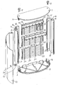
- 1 and 2 are the upper part and the identically formed lower part of a key cabinet.
- the two aforementioned parts have guide lugs 3 and 4, which can be plugged into cavities 5, 6 of two likewise identically formed side walls 7, 8.
- the side walls 7, 8 are cut to length endless profiles, which are preferably formed as aluminum extruded profiles.
- In the cavities 5, 6 protrude hollow profile webs 9, 10, the ends of which are used to receive screws 11, 12, which serve to connect the side walls 7, 8 with the upper part 1 and the lower part 2.
- the door 13 is made in the same way as the side walls 7, 8 from a cut to length endless profile, which is provided with an opening 14 for receiving a lock 15.
- the side walls 7, 8 have flanges 16, 17, the ends facing away from the cavities 5, 6 with guide grooves 18, 19 for receiving webs 20, 21 are located on opposite sides of segments 22, from which the rear wall of the Key box exists.
- the flanges 16, 17 are provided with holes 23 which allow attachment of the key box to a wall.
- the flanges 16, 17 are in other words guide and mounting flanges.
- the segments 22 used for producing the rear wall of the key box are preferably designed as plastic injection-molded parts. They have a plurality of rows of rectangular perforations 24, of which the perforations of the outer rows of perforations can be used to fasten key strips 25. Pin 26 and recesses 27 at the upper and lower edges of the segments 22 together with the guide grooves 18, 19 of the flanges 16, 17 ensure the cohesion of the segments 22 to form a rigid rear wall.
- the segmentation of the rear wall has the same effect on the economy of the production of key boxes of different sizes as the use of cut to length endless profiles and identical upper and lower parts.
Abstract
Description
Die Erfindung betrifft einen Schlüsselkasten mit einer Tür und einem durch die Tür verschließbaren Gehäuse aus Metall und/oder Kunststoff, bei dem die Rückwand des Gehäuses mit Mitteln zum Aufhängen von Schlüsseln versehen ist.The invention relates to a key box with a door and a closable by the door housing made of metal and / or plastic, wherein the rear wall of the housing is provided with means for suspending keys.
Aus der GB 890 914 A sind zwei Schlüsselkästen bekannt, von denen einer ein Gehäuse aus individuell auf die Größe des Kastens abgestimmten Blechzuschnitten und einer ein Gehäuse aus Holz aufweist. Der für die Herstellung von Blechgehäusen erforderliche Aufwand ist insbesondere dann unerwünscht hoch, wenn ein Hersteller ein Sortiment mit Schlüsselkästen anbieten möchte, die unterschiedlichen Aufnahmekapazitäten angepasste Größen aufweisen. Für Fälle der zuletzt genannten Art eignen sich eher Holzgehäuse, da die Länge der zu ihrer Herstellung verwendeten Bretter oder Leisten sich ohne weiteres variieren lässt. Holzkästen haben jedoch den Nachteil, dass zur Erzielung einer ausreichenden Stabilität ihres Gehäuses Verbindungen aus Nuten und Federn oder Bohrungen und Zapfen erforderlich sind, wobei auf eine Verleimung der miteinander zu verbindenden Teile regelmäßig nicht verzichtet werden kann. Der Aufwand zur Fertigung von Holzkästen ist mit anderen Worten ebenfalls erheblich.From GB 890 914 A two key boxes are known, one of which has a housing made of sheet metal blanks individually matched to the size of the box and one comprising a housing made of wood. The effort required for the production of sheet metal housings is undesirably high, in particular, when a manufacturer wishes to offer a range of key boxes which have sizes adapted to different receiving capacities. For cases of the latter type are more suitable wooden housing, since the length of the boards or strips used for their production can be varied easily. However, wooden boxes have the disadvantage that in order to achieve sufficient stability of their housing compounds of grooves and springs or holes and pins are required, with a gluing of the parts to be joined together can not be waived regularly. The cost of producing wooden boxes is also significant in other words.
Einen Schlüsselkasten bzw. Schlüsselschrank zeigt auch die CH 272 795 A. Er besteht - soweit man dies den Zeichnungen der genannten Schrift zu entnehmen vermag - vermutlich aus einem einstückigen Gehäuse und einer ebenfalls einstückigen Tür. Die Ausbildung des Gehäuses und der Tür gibt Anlass zu der Vermutung, dass es sich bei ihnen um Formteile handelt, die in ähnlicher Weise hergestellt sind, wie die Seitenwände und die Ober- und Unterteile eines aus der FR 1 164 566 A bekannten Schrankes, d. h. unter Verwendung spezieller Formwerkzeuge.A key box or key cabinet also shows the CH 272 795 A. It consists - as far as you can see in the drawings of the document mentioned - presumably from a one-piece housing and a likewise one-piece door. The training of the housing and the door gives rise to the assumption that they are molded parts made in a manner similar to the side walls and upper and lower parts of a cabinet known from FR 1 164 566 A, ie using special molding tools.
Der Erfindung liegt die Aufgabe zugrunde, einen Schlüsselkasten zu schaffen, dessen Aufbau eine gegenüber bekannten Herstellungsverfahren deutlich wirtschaftlichere Fertigung ermöglicht. Gelöst wird diese Aufgabe erfindungsgemäß dadurch, dass die Seitenwände und die Tür des Gehäuses aus auf Länge geschnittenen Endlosprofilen bestehen, die im Bereich ihrer der Tür abgewandten Ränder vertikal verlaufende Führungsnuten zur Aufnahme der Rückwand aufweisen, und dass die Seitenwände mit einem den Boden des Kastens bildenden Unterteil und einem die Decke des Kastens bildenden Oberteil verschraubt sind.The invention has for its object to provide a key box, the structure of which enables a much more economical production compared to known manufacturing process. This object is achieved according to the invention in that the side walls and the door of the housing consist of cut to length endless profiles having in the region of their edges facing away from the door vertically extending guide grooves for receiving the rear wall, and that the side walls forming a bottom of the box Bottom part and a ceiling of the box forming upper part are screwed.
Der erfindungsgemäße Schlüsselkasten bietet den Vorteil, dass sein Fassungsvermögen auf einfache Weise durch die Verwendung von auf Länge geschnittenen Seitenwänden variiert werden kann und dass der Aufwand für die Herstellung seiner Einzelteile und deren Montage gering ist.The key box according to the invention has the advantage that its capacity can be varied easily by the use of cut to length side walls and that the cost of producing its parts and their installation is low.
Weitere Merkmale und Einzelheiten der Erfindung ergeben sich aus den Unteransprüchen und der nachstehenden Beschreibung einer in der beigefügten Zeichnung dargestellten Ausführungsform eines Schlüsselkastens.Further features and details of the invention will become apparent from the dependent claims and the following description of an embodiment of a key box shown in the accompanying drawings.
In der einzigen Figur sind 1 und 2 das Oberteil und das identisch ausgebildete Unterteil eines Schlüsselschrankes. Die beiden vorgenannten Teile weisen Führungsansätze 3 und 4 auf, die in Hohlräume 5, 6 zweier ebenfalls identisch ausgebildeter Seitenwände 7, 8 steckbar sind. Bei den Seitenwänden 7, 8 handelt es sich um auf Länge geschnittene Endlosprofile, die vorzugsweise als Aluminium-Strangpressprofile ausgebildet sind. In die Hohlräume 5, 6 ragen Hohlprofilstege 9, 10, deren Enden zur Aufnahme von Schrauben 11, 12 genutzt werden, die zur Verbindung der Seitenwände 7, 8 mit dem Oberteil 1 und dem Unterteil 2 dienen.In the single figure, 1 and 2 are the upper part and the identically formed lower part of a key cabinet. The two aforementioned parts have
Die Tür 13 besteht in gleicher Weise wie die Seitenwände 7, 8 aus einem auf Länge geschnittenen Endlosprofil, das mit einer Öffnung 14 zur Aufnahme eines Schlosses 15 versehen ist.The
Die Seitenwände 7, 8 weisen Flansche 16, 17 auf, deren den Hohlräumen 5, 6 abgewandte Enden mit Führungsnuten 18, 19 zur Aufnahme von Stegen 20, 21 dienen, die sich an sich gegenüberliegenden Seiten von Segmenten 22 befinden, aus denen die Rückwand des Schlüsselkastens besteht. Außerdem sind die Flansche 16, 17 mit Bohrungen 23 versehen, die eine Befestigung des Schlüsselkastens an einer Wand ermöglichen. Die Flansche 16, 17 stellen mit anderen Worten Führungs- und Befestigungsflansche dar.The
Die zur Herstellung der Rückwand des Schlüsselkastens verwendeten Segmente 22 sind vorzugsweise als Kunststoffspritzgussteile ausgebildet. Sie weisen mehrere Reihen rechteckiger Perforationen 24 auf, von denen die Perforationen der äußeren Perforationsreihen zur Befestigung von Schlüsselleisten 25 genutzt werden können. Zapfen 26 und Ausnehmungen 27 an den oberen und unteren Rändern der Segmente 22 sichern zusammen mit den Führungsnuten 18, 19 der Flansche 16, 17 den Zusammenhalt der Segmente 22 zu einer steifen Rückwand. Die Segmentierung der Rückwand wirkt sich in gleicher Weise günstig auf die Wirtschaftlichkeit der Fertigung von Schlüsselkästen unterschiedlicher Größe aus wie die Verwendung von auf Länge geschnittenen Endlosprofilen und identischen Ober- und Unterteilen.The
Claims (12)
- Key box having a door (13) and a metal and/or plastics housing which can be closed by the door (13), in which the rear wall (22, 22) of the housing is provided with key-hanging means, characterized in that the side walls (7, 8) and the door (13) of the housing consist of cut-to-length continuous profiles which, in the region of their edges facing away from the door (13), have vertically running guide grooves (18, 19) for receiving the rear wall (22, 22), and in that the side walls (7, 8) are screwed together with a bottom part (2) forming the floor of the box and a top part (1) forming the roof of the box.
- Key box according to claim 1, characterized in that the side walls (7, 8) are configured partially as hollow profiles.
- Key box according to claim 2, characterized in that the top part (1) and the bottom part (2) are provided with guide lugs (3, 4), which jut into cavities (5, 6) in the side walls (7, 8).
- Key box according to one of claims 1 to 3, characterized in that the side walls (7, 8) and the door (13) are configured as aluminum extruded profiles.
- Key box according to one of claims 1 to 4, characterized in that the top part (1) and the bottom part (2) are configured as plastics injection-molded parts.
- Key box according to one of claims 1 to 5, characterized in that the rear wall consists of a plurality of segments (22) disposed one above the other.
- Key box according to claim 6, characterized in that the segments (22) of the rear wall are configured as plastics injection-molded parts.
- Key box according to one of claims 1 to 7, characterized in that the side walls (7, 8) have flanges (16, 17) forming parts of the rear wall.
- Key box according to claims 6 to 8, characterized in that the flanges (16, 17) of the side walls (7, 8) are configured as guide flanges for the segments (22) forming the actual rear wall (22-22) and as fastening flanges for the key box.
- Key box according to one of claims 1 to 9, characterized in that the key-hanging means are formed by at least one key rail (25), which can be hung in perforations (24) in the rear wall (22-22).
- Key box according to one of claims 1 to 10, characterized in that the top part (1) and the bottom part (2) of the housing are identically configured.
- Key box according to one of claims 1 to 11, characterized in that the side walls (7, 8) of the housing are identically configured.
Priority Applications (1)
| Application Number | Priority Date | Filing Date | Title |
|---|---|---|---|
| PL04764919T PL1659907T3 (en) | 2003-09-04 | 2004-09-03 | Boxes for keys |
Applications Claiming Priority (2)
| Application Number | Priority Date | Filing Date | Title |
|---|---|---|---|
| DE10341494A DE10341494B4 (en) | 2003-09-04 | 2003-09-04 | key Cabinet |
| PCT/EP2004/009976 WO2005023065A1 (en) | 2003-09-04 | 2004-09-03 | Boxes for keys |
Publications (2)
| Publication Number | Publication Date |
|---|---|
| EP1659907A1 EP1659907A1 (en) | 2006-05-31 |
| EP1659907B1 true EP1659907B1 (en) | 2006-12-27 |
Family
ID=34258510
Family Applications (1)
| Application Number | Title | Priority Date | Filing Date |
|---|---|---|---|
| EP04764919A Active EP1659907B1 (en) | 2003-09-04 | 2004-09-03 | Boxes for keys |
Country Status (9)
| Country | Link |
|---|---|
| US (1) | US7874628B2 (en) |
| EP (1) | EP1659907B1 (en) |
| CN (1) | CN100484442C (en) |
| AT (1) | ATE349174T1 (en) |
| DE (2) | DE10341494B4 (en) |
| ES (1) | ES2278337T3 (en) |
| PL (1) | PL1659907T3 (en) |
| RU (1) | RU2324416C2 (en) |
| WO (1) | WO2005023065A1 (en) |
Families Citing this family (2)
| Publication number | Priority date | Publication date | Assignee | Title |
|---|---|---|---|---|
| US9226577B2 (en) * | 2012-07-26 | 2016-01-05 | Prosteel Security Products Inc. | Modular safe interior |
| GB201700060D0 (en) * | 2017-01-03 | 2017-02-15 | Ec Goundworks Ltd | Modular safety station |
Family Cites Families (24)
| Publication number | Priority date | Publication date | Assignee | Title |
|---|---|---|---|---|
| US1978494A (en) * | 1929-11-23 | 1934-10-30 | Junkers Hugo | Hollow structural element |
| US2483606A (en) * | 1946-10-25 | 1949-10-04 | Medart Company | Knockdown utility cabinet |
| US2728624A (en) * | 1952-07-23 | 1955-12-27 | Caruso Mario | Cabinet structures |
| CH272795A (en) * | 1953-07-23 | 1951-01-15 | Bigler Spichiger & Cie Ag | Key cabinet. |
| FR1164566A (en) * | 1956-09-21 | 1958-10-13 | Furniture composed of molded elements, with or without doors and drawers, which can form by assembly, various combinations | |
| GB890914A (en) * | 1957-08-13 | 1962-03-07 | Scipione Roger Manzardo | Improvements in or relating to key filing devices |
| US3070235A (en) * | 1957-08-13 | 1962-12-25 | Manzardo Scipione Roger | Key filing system |
| US3754806A (en) * | 1970-08-05 | 1973-08-28 | Toyo Plastic Co Ltd | Frame structure for bathroom cabinets |
| US3813138A (en) * | 1972-08-31 | 1974-05-28 | M Doohan | Jewelry organizing cabinet |
| DE2760124A1 (en) * | 1976-05-21 | 1983-05-26 | ||
| DE3541141A1 (en) * | 1985-11-21 | 1987-05-27 | Dapper Saalfels Manfred Von | Money tray |
| US5076454A (en) * | 1989-02-07 | 1991-12-31 | North American Van Lines, Inc. | Knock-down shipping and storage container |
| CN2123211U (en) * | 1992-04-15 | 1992-12-02 | 济南达明工业新技术发展有限公司 | Key box and board specially used for holding keys |
| DE9302769U1 (en) * | 1993-02-25 | 1993-04-08 | Knuerr-Mechanik Fuer Die Elektronik Ag, 8000 Muenchen, De | |
| US5451102A (en) * | 1994-01-13 | 1995-09-19 | Chuan; Yuan-Jung | Cabinet with connecting mechanism for two adjacent wall plate |
| US5411139A (en) * | 1994-02-14 | 1995-05-02 | Victory; James | Orientable keybox with keypanels vertically and horizontally extendable |
| DE19501033A1 (en) * | 1995-01-16 | 1996-07-18 | Kemmlit Bauelemente Gmbh | Metal cabinet |
| US5690212A (en) * | 1996-09-23 | 1997-11-25 | Huang Hsu; Chin-Lien | Box for storing keys |
| US5921646A (en) * | 1997-07-22 | 1999-07-13 | Kenmark Industrial, Co., Ltd. | Combination of easily assemblable and movable cabinet with its engagement components |
| US5975660A (en) * | 1998-06-02 | 1999-11-02 | Suncast Corporation | Cabinet |
| DE19956052C1 (en) * | 1999-11-22 | 2001-01-25 | Matthias Sandrock | Key deposit box has access to deposit chamber holding key only permitted upon verification of authorisation via interccom device |
| US6422671B1 (en) * | 2000-01-06 | 2002-07-23 | Block And Company, Inc. | Key cabinet with staggered key panels |
| CN2461433Y (en) * | 2001-01-15 | 2001-11-28 | 郭鹭声 | Management case for keys |
| US6474759B2 (en) * | 2001-02-09 | 2002-11-05 | L & F Platics Co., Ltd. | Cabinet |
-
2003
- 2003-09-04 DE DE10341494A patent/DE10341494B4/en not_active Expired - Lifetime
-
2004
- 2004-09-03 PL PL04764919T patent/PL1659907T3/en unknown
- 2004-09-03 WO PCT/EP2004/009976 patent/WO2005023065A1/en active IP Right Grant
- 2004-09-03 CN CNB2004800240546A patent/CN100484442C/en active Active
- 2004-09-03 RU RU2006110634/11A patent/RU2324416C2/en active
- 2004-09-03 AT AT04764919T patent/ATE349174T1/en not_active IP Right Cessation
- 2004-09-03 DE DE502004002486T patent/DE502004002486D1/en active Active
- 2004-09-03 EP EP04764919A patent/EP1659907B1/en active Active
- 2004-09-03 US US10/565,475 patent/US7874628B2/en not_active Expired - Fee Related
- 2004-09-03 ES ES04764919T patent/ES2278337T3/en active Active
Also Published As
| Publication number | Publication date |
|---|---|
| RU2006110634A (en) | 2006-08-10 |
| PL1659907T3 (en) | 2007-05-31 |
| EP1659907A1 (en) | 2006-05-31 |
| WO2005023065A1 (en) | 2005-03-17 |
| DE502004002486D1 (en) | 2007-02-08 |
| DE10341494A1 (en) | 2005-04-07 |
| CN100484442C (en) | 2009-05-06 |
| DE10341494B4 (en) | 2005-10-13 |
| US20060207953A1 (en) | 2006-09-21 |
| ATE349174T1 (en) | 2007-01-15 |
| ES2278337T3 (en) | 2007-08-01 |
| US7874628B2 (en) | 2011-01-25 |
| RU2324416C2 (en) | 2008-05-20 |
| CN1838903A (en) | 2006-09-27 |
Similar Documents
| Publication | Publication Date | Title |
|---|---|---|
| EP1846709B1 (en) | Refrigerator door | |
| EP2467657B1 (en) | Door for a household appliance having a handle insert | |
| EP1659907B1 (en) | Boxes for keys | |
| EP2351893B1 (en) | Attachment socket, in particular for roof openings, e.g. for smoke and heat extractors | |
| CH685357A5 (en) | Room ventilation equipment for installation by window or door | |
| DE202008004145U1 (en) | furniture body | |
| AT389990B (en) | HOUSE MAILBOX | |
| DE2806554C2 (en) | Shutter box | |
| DE10259749A1 (en) | Refrigeration device and door for a refrigeration device | |
| EP0804108A1 (en) | Metal locker | |
| DE8310661U1 (en) | POLYGONAL PLANT CONTAINER WITH PANELING | |
| DE2939677A1 (en) | THIN WALL OR PANEL, YOUR ELEMENTS AND WALL OR BOX CONSTRUCTION CONSTRUCTED FROM THESE ELEMENTS | |
| DE102008051356B4 (en) | partition system | |
| EP1070826A2 (en) | Roller shutter box | |
| DE3343773C2 (en) | ||
| DE3521014A1 (en) | Holder for number plate | |
| DE202008007361U1 (en) | Hanger for a drawer | |
| DE2555423A1 (en) | Concealed wall junction box for wiring installations - has hinged sides for adjusting the box height composed of parallel strips with flexible film hinge | |
| DE20313936U1 (en) | Key safe has curved door and curved side walls which are screwed to its top and bottom, back wall made up of separate segments being slotted into grooves in edges of side walls | |
| DE102014017627A1 (en) | Shelf and / or room divider device | |
| DE202007002913U1 (en) | wall element | |
| DE2042942A1 (en) | Cable duct and mounting rail kit | |
| DE2223217A1 (en) | INSTALLABLE AND REMOVABLE PARTITION WALL | |
| DE1554195A1 (en) | Toilet closets | |
| DE2407985A1 (en) | SERIES OF UNIFORM PARTS FOR THE PRODUCTION OF FURNITURE |
Legal Events
| Date | Code | Title | Description |
|---|---|---|---|
| PUAI | Public reference made under article 153(3) epc to a published international application that has entered the european phase |
Free format text: ORIGINAL CODE: 0009012 |
|
| 17P | Request for examination filed |
Effective date: 20060227 |
|
| AK | Designated contracting states |
Kind code of ref document: A1 Designated state(s): AT BE BG CH CY CZ DE DK EE ES FI FR GB GR HU IE IT LI LU MC NL PL PT RO SE SI SK TR |
|
| GRAP | Despatch of communication of intention to grant a patent |
Free format text: ORIGINAL CODE: EPIDOSNIGR1 |
|
| GRAS | Grant fee paid |
Free format text: ORIGINAL CODE: EPIDOSNIGR3 |
|
| GRAA | (expected) grant |
Free format text: ORIGINAL CODE: 0009210 |
|
| DAX | Request for extension of the european patent (deleted) | ||
| AK | Designated contracting states |
Kind code of ref document: B1 Designated state(s): AT BE BG CH CY CZ DE DK EE ES FI FR GB GR HU IE IT LI LU MC NL PL PT RO SE SI SK TR |
|
| PG25 | Lapsed in a contracting state [announced via postgrant information from national office to epo] |
Ref country code: SI Free format text: LAPSE BECAUSE OF FAILURE TO SUBMIT A TRANSLATION OF THE DESCRIPTION OR TO PAY THE FEE WITHIN THE PRESCRIBED TIME-LIMIT Effective date: 20061227 Ref country code: SK Free format text: LAPSE BECAUSE OF FAILURE TO SUBMIT A TRANSLATION OF THE DESCRIPTION OR TO PAY THE FEE WITHIN THE PRESCRIBED TIME-LIMIT Effective date: 20061227 Ref country code: RO Free format text: LAPSE BECAUSE OF FAILURE TO SUBMIT A TRANSLATION OF THE DESCRIPTION OR TO PAY THE FEE WITHIN THE PRESCRIBED TIME-LIMIT Effective date: 20061227 Ref country code: FI Free format text: LAPSE BECAUSE OF FAILURE TO SUBMIT A TRANSLATION OF THE DESCRIPTION OR TO PAY THE FEE WITHIN THE PRESCRIBED TIME-LIMIT Effective date: 20061227 Ref country code: IT Free format text: LAPSE BECAUSE OF FAILURE TO SUBMIT A TRANSLATION OF THE DESCRIPTION OR TO PAY THE FEE WITHIN THE PRESCRIBED TIME-LIMIT;WARNING: LAPSES OF ITALIAN PATENTS WITH EFFECTIVE DATE BEFORE 2007 MAY HAVE OCCURRED AT ANY TIME BEFORE 2007. THE CORRECT EFFECTIVE DATE MAY BE DIFFERENT FROM THE ONE RECORDED. Effective date: 20061227 Ref country code: DK Free format text: LAPSE BECAUSE OF FAILURE TO SUBMIT A TRANSLATION OF THE DESCRIPTION OR TO PAY THE FEE WITHIN THE PRESCRIBED TIME-LIMIT Effective date: 20061227 Ref country code: IE Free format text: LAPSE BECAUSE OF FAILURE TO SUBMIT A TRANSLATION OF THE DESCRIPTION OR TO PAY THE FEE WITHIN THE PRESCRIBED TIME-LIMIT Effective date: 20061227 Ref country code: CZ Free format text: LAPSE BECAUSE OF FAILURE TO SUBMIT A TRANSLATION OF THE DESCRIPTION OR TO PAY THE FEE WITHIN THE PRESCRIBED TIME-LIMIT Effective date: 20061227 |
|
| REG | Reference to a national code |
Ref country code: GB Ref legal event code: FG4D Free format text: NOT ENGLISH |
|
| REG | Reference to a national code |
Ref country code: IE Ref legal event code: FG4D Free format text: LANGUAGE OF EP DOCUMENT: GERMAN |
|
| REF | Corresponds to: |
Ref document number: 502004002486 Country of ref document: DE Date of ref document: 20070208 Kind code of ref document: P |
|
| GBT | Gb: translation of ep patent filed (gb section 77(6)(a)/1977) |
Effective date: 20070227 |
|
| PG25 | Lapsed in a contracting state [announced via postgrant information from national office to epo] |
Ref country code: BG Free format text: LAPSE BECAUSE OF FAILURE TO SUBMIT A TRANSLATION OF THE DESCRIPTION OR TO PAY THE FEE WITHIN THE PRESCRIBED TIME-LIMIT Effective date: 20070327 |
|
| REG | Reference to a national code |
Ref country code: SE Ref legal event code: TRGR |
|
| PG25 | Lapsed in a contracting state [announced via postgrant information from national office to epo] |
Ref country code: PT Free format text: LAPSE BECAUSE OF FAILURE TO SUBMIT A TRANSLATION OF THE DESCRIPTION OR TO PAY THE FEE WITHIN THE PRESCRIBED TIME-LIMIT Effective date: 20070528 |
|
| REG | Reference to a national code |
Ref country code: PL Ref legal event code: T3 |
|
| ET | Fr: translation filed | ||
| REG | Reference to a national code |
Ref country code: ES Ref legal event code: FG2A Ref document number: 2278337 Country of ref document: ES Kind code of ref document: T3 |
|
| PLBE | No opposition filed within time limit |
Free format text: ORIGINAL CODE: 0009261 |
|
| STAA | Information on the status of an ep patent application or granted ep patent |
Free format text: STATUS: NO OPPOSITION FILED WITHIN TIME LIMIT |
|
| 26N | No opposition filed |
Effective date: 20070928 |
|
| PG25 | Lapsed in a contracting state [announced via postgrant information from national office to epo] |
Ref country code: MC Free format text: LAPSE BECAUSE OF NON-PAYMENT OF DUE FEES Effective date: 20070930 Ref country code: GR Free format text: LAPSE BECAUSE OF FAILURE TO SUBMIT A TRANSLATION OF THE DESCRIPTION OR TO PAY THE FEE WITHIN THE PRESCRIBED TIME-LIMIT Effective date: 20070328 |
|
| PG25 | Lapsed in a contracting state [announced via postgrant information from national office to epo] |
Ref country code: AT Free format text: LAPSE BECAUSE OF NON-PAYMENT OF DUE FEES Effective date: 20070903 |
|
| PG25 | Lapsed in a contracting state [announced via postgrant information from national office to epo] |
Ref country code: EE Free format text: LAPSE BECAUSE OF FAILURE TO SUBMIT A TRANSLATION OF THE DESCRIPTION OR TO PAY THE FEE WITHIN THE PRESCRIBED TIME-LIMIT Effective date: 20061227 |
|
| REG | Reference to a national code |
Ref country code: CH Ref legal event code: PL |
|
| PG25 | Lapsed in a contracting state [announced via postgrant information from national office to epo] |
Ref country code: CH Free format text: LAPSE BECAUSE OF NON-PAYMENT OF DUE FEES Effective date: 20070930 Ref country code: LI Free format text: LAPSE BECAUSE OF NON-PAYMENT OF DUE FEES Effective date: 20070930 |
|
| PG25 | Lapsed in a contracting state [announced via postgrant information from national office to epo] |
Ref country code: LU Free format text: LAPSE BECAUSE OF NON-PAYMENT OF DUE FEES Effective date: 20070903 Ref country code: CY Free format text: LAPSE BECAUSE OF FAILURE TO SUBMIT A TRANSLATION OF THE DESCRIPTION OR TO PAY THE FEE WITHIN THE PRESCRIBED TIME-LIMIT Effective date: 20061227 |
|
| PG25 | Lapsed in a contracting state [announced via postgrant information from national office to epo] |
Ref country code: HU Free format text: LAPSE BECAUSE OF FAILURE TO SUBMIT A TRANSLATION OF THE DESCRIPTION OR TO PAY THE FEE WITHIN THE PRESCRIBED TIME-LIMIT Effective date: 20070628 Ref country code: TR Free format text: LAPSE BECAUSE OF FAILURE TO SUBMIT A TRANSLATION OF THE DESCRIPTION OR TO PAY THE FEE WITHIN THE PRESCRIBED TIME-LIMIT Effective date: 20061227 |
|
| PG25 | Lapsed in a contracting state [announced via postgrant information from national office to epo] |
Ref country code: CH Free format text: LAPSE BECAUSE OF NON-PAYMENT OF DUE FEES Effective date: 20080930 Ref country code: LI Free format text: LAPSE BECAUSE OF NON-PAYMENT OF DUE FEES Effective date: 20080930 |
|
| REG | Reference to a national code |
Ref country code: DE Ref legal event code: R082 Ref document number: 502004002486 Country of ref document: DE Representative=s name: BECKORD & NIEDLICH PATENTANWALTSKANZLEI, DE |
|
| REG | Reference to a national code |
Ref country code: DE Ref legal event code: R082 Ref document number: 502004002486 Country of ref document: DE Representative=s name: BECKORD & NIEDLICH PATENTANWALTSKANZLEI, DE Effective date: 20140114 Ref country code: DE Ref legal event code: R081 Ref document number: 502004002486 Country of ref document: DE Owner name: "DURABLE" HUNKE & JOCHHEIM GMBH & CO. KOMMANDI, DE Free format text: FORMER OWNER: "DURABLE" HUNKE & JOCHHEIM GMBH & CO. KOMMANDITGESELLSCHAFT, 58636 ISERLOHN, DE Effective date: 20140114 |
|
| REG | Reference to a national code |
Ref country code: FR Ref legal event code: PLFP Year of fee payment: 13 |
|
| REG | Reference to a national code |
Ref country code: FR Ref legal event code: PLFP Year of fee payment: 14 |
|
| REG | Reference to a national code |
Ref country code: FR Ref legal event code: PLFP Year of fee payment: 15 |
|
| PGFP | Annual fee paid to national office [announced via postgrant information from national office to epo] |
Ref country code: NL Payment date: 20190918 Year of fee payment: 16 |
|
| REG | Reference to a national code |
Ref country code: DE Ref legal event code: R084 Ref document number: 502004002486 Country of ref document: DE |
|
| REG | Reference to a national code |
Ref country code: NL Ref legal event code: MM Effective date: 20201001 |
|
| PG25 | Lapsed in a contracting state [announced via postgrant information from national office to epo] |
Ref country code: NL Free format text: LAPSE BECAUSE OF NON-PAYMENT OF DUE FEES Effective date: 20201001 |
|
| P01 | Opt-out of the competence of the unified patent court (upc) registered |
Effective date: 20230516 |
|
| PGFP | Annual fee paid to national office [announced via postgrant information from national office to epo] |
Ref country code: GB Payment date: 20230920 Year of fee payment: 20 |
|
| PGFP | Annual fee paid to national office [announced via postgrant information from national office to epo] |
Ref country code: SE Payment date: 20230920 Year of fee payment: 20 Ref country code: PL Payment date: 20230825 Year of fee payment: 20 Ref country code: FR Payment date: 20230928 Year of fee payment: 20 Ref country code: DE Payment date: 20230930 Year of fee payment: 20 Ref country code: BE Payment date: 20230920 Year of fee payment: 20 |
|
| PGFP | Annual fee paid to national office [announced via postgrant information from national office to epo] |
Ref country code: ES Payment date: 20231123 Year of fee payment: 20 |