EP2467657B1 - Door for a household appliance having a handle insert - Google Patents
Door for a household appliance having a handle insert Download PDFInfo
- Publication number
- EP2467657B1 EP2467657B1 EP10743125.6A EP10743125A EP2467657B1 EP 2467657 B1 EP2467657 B1 EP 2467657B1 EP 10743125 A EP10743125 A EP 10743125A EP 2467657 B1 EP2467657 B1 EP 2467657B1
- Authority
- EP
- European Patent Office
- Prior art keywords
- door
- handle insert
- handle
- end pieces
- insert
- Prior art date
- Legal status (The legal status is an assumption and is not a legal conclusion. Google has not performed a legal analysis and makes no representation as to the accuracy of the status listed.)
- Active
Links
- 238000001125 extrusion Methods 0.000 claims description 11
- 239000004033 plastic Substances 0.000 claims description 10
- 238000001746 injection moulding Methods 0.000 claims description 8
- 238000000034 method Methods 0.000 claims description 7
- 238000002347 injection Methods 0.000 claims description 6
- 239000007924 injection Substances 0.000 claims description 6
- 238000004519 manufacturing process Methods 0.000 claims description 6
- 239000003086 colorant Substances 0.000 claims description 3
- 238000005057 refrigeration Methods 0.000 claims description 3
- 238000003780 insertion Methods 0.000 claims description 2
- 230000037431 insertion Effects 0.000 claims description 2
- 238000009966 trimming Methods 0.000 claims 1
- 238000005520 cutting process Methods 0.000 description 4
- 238000004026 adhesive bonding Methods 0.000 description 3
- 239000000243 solution Substances 0.000 description 3
- 229910052751 metal Inorganic materials 0.000 description 2
- 239000002184 metal Substances 0.000 description 2
- 229910000831 Steel Inorganic materials 0.000 description 1
- 229910052782 aluminium Inorganic materials 0.000 description 1
- XAGFODPZIPBFFR-UHFFFAOYSA-N aluminium Chemical compound [Al] XAGFODPZIPBFFR-UHFFFAOYSA-N 0.000 description 1
- 238000005253 cladding Methods 0.000 description 1
- 238000005187 foaming Methods 0.000 description 1
- 239000011810 insulating material Substances 0.000 description 1
- 239000012774 insulation material Substances 0.000 description 1
- 239000000463 material Substances 0.000 description 1
- 239000010959 steel Substances 0.000 description 1
Images


Classifications
-
- F—MECHANICAL ENGINEERING; LIGHTING; HEATING; WEAPONS; BLASTING
- F25—REFRIGERATION OR COOLING; COMBINED HEATING AND REFRIGERATION SYSTEMS; HEAT PUMP SYSTEMS; MANUFACTURE OR STORAGE OF ICE; LIQUEFACTION SOLIDIFICATION OF GASES
- F25D—REFRIGERATORS; COLD ROOMS; ICE-BOXES; COOLING OR FREEZING APPARATUS NOT OTHERWISE PROVIDED FOR
- F25D23/00—General constructional features
- F25D23/02—Doors; Covers
- F25D23/028—Details
-
- E—FIXED CONSTRUCTIONS
- E05—LOCKS; KEYS; WINDOW OR DOOR FITTINGS; SAFES
- E05B—LOCKS; ACCESSORIES THEREFOR; HANDCUFFS
- E05B1/00—Knobs or handles for wings; Knobs, handles, or press buttons for locks or latches on wings
- E05B1/0015—Knobs or handles which do not operate the bolt or lock, e.g. non-movable; Mounting thereof
-
- F—MECHANICAL ENGINEERING; LIGHTING; HEATING; WEAPONS; BLASTING
- F24—HEATING; RANGES; VENTILATING
- F24C—DOMESTIC STOVES OR RANGES ; DETAILS OF DOMESTIC STOVES OR RANGES, OF GENERAL APPLICATION
- F24C15/00—Details
- F24C15/02—Doors specially adapted for stoves or ranges
- F24C15/024—Handles
-
- E—FIXED CONSTRUCTIONS
- E05—LOCKS; KEYS; WINDOW OR DOOR FITTINGS; SAFES
- E05B—LOCKS; ACCESSORIES THEREFOR; HANDCUFFS
- E05B17/00—Accessories in connection with locks
- E05B17/0004—Lock assembling or manufacturing
- E05B17/0008—Lock parts made by extrusion process
-
- F—MECHANICAL ENGINEERING; LIGHTING; HEATING; WEAPONS; BLASTING
- F25—REFRIGERATION OR COOLING; COMBINED HEATING AND REFRIGERATION SYSTEMS; HEAT PUMP SYSTEMS; MANUFACTURE OR STORAGE OF ICE; LIQUEFACTION SOLIDIFICATION OF GASES
- F25D—REFRIGERATORS; COLD ROOMS; ICE-BOXES; COOLING OR FREEZING APPARATUS NOT OTHERWISE PROVIDED FOR
- F25D2323/00—General constructional features not provided for in other groups of this subclass
- F25D2323/02—Details of doors or covers not otherwise covered
- F25D2323/022—Doors that can be pivoted either left-handed or right-handed
-
- F—MECHANICAL ENGINEERING; LIGHTING; HEATING; WEAPONS; BLASTING
- F25—REFRIGERATION OR COOLING; COMBINED HEATING AND REFRIGERATION SYSTEMS; HEAT PUMP SYSTEMS; MANUFACTURE OR STORAGE OF ICE; LIQUEFACTION SOLIDIFICATION OF GASES
- F25D—REFRIGERATORS; COLD ROOMS; ICE-BOXES; COOLING OR FREEZING APPARATUS NOT OTHERWISE PROVIDED FOR
- F25D2400/00—General features of, or devices for refrigerators, cold rooms, ice-boxes, or for cooling or freezing apparatus not covered by any other subclass
- F25D2400/18—Aesthetic features
Definitions
- the invention relates to a door for a household appliance, in particular for a household refrigerator, a handle insert being integrated in at least one side cheek of the door.
- the invention is also directed to a corresponding household appliance and to a method for producing a handle insert.
- handles for the doors of household appliances are known. On the one hand, it is possible to place door handles on the outside of the door.
- the handles are often formed by handle bars of different lengths, which are mounted between two pedestals. Since most household appliances have the choice of hinging the door either on the left or right of the body, solutions are often chosen in which the handles can be attached to the door either on the right or left.
- the disclosure DE 10 2007 055 174 A1 shows a door for a refrigerator with an outer shell which is foamed with insulation material and which comprises an outer plate which integrally covers an outside of the door and at least part of the side flanks of the door.
- the disclosure FR 1 367 611 A shows a door frame, which is composed of four side parts. A cover is inserted in the door frame. A doorknob is attached to the outside of the cover.
- the utility model DE 20 2006 00 24 58 U1 shows a door for refrigerators and freezers, the door having at least one profile strip and a handle that can be mounted on the profile strip.
- the object of the invention is therefore to provide a door for a household appliance with a handle insert which can be produced particularly cost-effectively.
- a door with a handle insert integrated into a side cheek the handle insert being divided into at least two parts in the longitudinal direction of the side cheek.
- the handle insert is divided into three parts in the longitudinal direction of the side cheek. This offers the advantage that the most varied length variants are represented, in that one or more of the parts are used identically for different devices, while other parts are exchanged, in particular in different lengths. This allows parts of the handle insert to be used for doors of different heights or widths.
- a “side wall” means one of the four narrow sides of the door, which are located between the outside or front and the inside of the door.
- the invention can be applied to an upper or lower side cheek as well as to one or both of the side side cheeks.
- the door of a household refrigeration device e.g. B. a refrigerator, a freezer, a wine cabinet or a fridge-freezer.
- a household refrigeration device e.g. B. a refrigerator, a freezer, a wine cabinet or a fridge-freezer.
- the handle insert according to the invention is preferably integrated in one or both side cheeks of the door.
- the handle insert is integrated in the upper side wall of the door.
- the handle insert is composed of at least one middle part and at least two end pieces. This has the advantage that the two end pieces can each be used for different household appliances, while the middle part is exchanged for different types of devices. In particular, it is advantageous to design the middle part as a profile piece, which is used in different device types in different lengths. Embodiments are also encompassed by the invention in which a plurality of middle parts are present.
- the handle insert can also have more than two end pieces, for. B. by forming each end of the handle insert from a plurality of end pieces.
- a handle insert can have two end pieces of the same shape or two different end pieces at both ends.
- the handle insert has a recessed grip, that is to say a depression which extends generally in the longitudinal direction of the side cheek and into which the user engages when the door is opened.
- the handle insert can also have a protruding part or another type of shape which is suitable as a handle for opening the door.
- the parts of the handle insert are preferably made of plastic, for example PE or another injection-moldable and particularly preferably additionally extrudable plastic. Alternatively, however, the parts can also be made of rubber or sheet metal.
- the end pieces of the handle insert are particularly preferably configured as plastic injection molded parts.
- This allows cost-effective production with simultaneous free choice of shape.
- the middle part is designed according to the invention as an extrusion profile. This offers the advantage that the middle part can be produced as an endless product and then middle parts with different lengths can be produced in a simple manner by cutting the extrusion profile to length.
- the two end pieces can preferably be used in any length variant. This means a great savings potential with the injection molding tools, since with the known solution an extra injection molding tool had to be manufactured for each length. In this embodiment, on the other hand, only one or possibly two injection molding tools are used and needed an extrusion tool.
- the central part designed as an extrusion profile also preferably consists of plastic.
- a handle insert is particularly preferably integrated in each of the two side cheeks of the door.
- the two handle inserts preferably have the same length and are preferably designed as mirror images of one another. This can be achieved particularly advantageously in that the two handle inserts are each constructed from the same end pieces and the same middle parts, the end piece arranged on the left side cheek at the top being arranged on the right side cheek at the bottom and vice versa, ie that on the left side cheek end piece located at the bottom is located on the right side cheek at the top.
- two identical middle parts, two identical first end pieces and two identical second end pieces are required for the two handle inserts, a first and a second end piece preferably being constructed mirror-inverted to one another.
- the outside of the door is made from a door panel, e.g. B. from a metal sheet made of aluminum or steel.
- a door panel e.g. B. from a metal sheet made of aluminum or steel.
- Such door panels form an aesthetically pleasing front of the door.
- the door panel can be bent inwards to form the side panels.
- the handle insert is then inserted into a cutout in the side cheek.
- the side cheek can also be formed entirely or partially by the handle insert. This is then z. B. positive, non-positive or material, z. B. attached by gluing to the door panel.
- the handle insert is positively held in the side cheek of the door, e.g. B. by a locking, clamping or plug-in mechanism.
- the handle insert can also be held in the side cheek by gluing or foaming the space between the outside and the inner shell of the door.
- the individual parts of the handle insert can preferably be fastened to one another in a form-fitting, material-locking or non-positive manner, in particular by means of a latching, clamping or plug connection.
- the multi-part design of the handle insert also offers advantages for the design.
- the individual parts of the handle insert can be contrasted in color, z. B.
- the two end pieces can be made with a different color than the central part.
- the invention is also directed to a household appliance designed with a corresponding door.
- the object of the invention is also achieved by a method for producing a handle insert for insertion into the side cheek of a door of a household appliance, the handle insert being composed of at least one middle part and at least two end pieces.
- the process includes the following steps: (a) injection molding the end pieces of the handle insert, (b) extruding an extrusion profile, (c) cutting to length the extrusion profile for producing a middle part, and (d) assembling the end pieces and the middle part into a handle insert.
- the latter happens for. B. by inserting the end pieces from above and below on the middle part.
- each handle insert has an end piece at each end
- the two end pieces can either have exactly the same shape, so that they can be molded in the same injection mold.
- the end pieces can be designed differently, e.g. B. of different lengths and / or mirror-inverted, so that they are cast in different injection molds.
- the extrusion profile is e.g. B. substantially U-shaped to thereby form a recessed grip in the middle part.
- a handle insert as described above can preferably be produced.
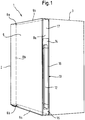
- Fig. 1 shows a perspective schematic representation of a household appliance 1, in particular a refrigerator, with a body 3 and a door attached to it 2.
- the door 2 has a front side 5, the z. B. is formed by a door panel.
- the lower side panel of the door is designated 9a, the upper side panel 9b, and the right and left side panels 8a and 8b.
- the door is hinged to the body 3 on the left side at the two pivot points 6a and 6b, so that a handle for opening the door is necessary on the right side.
- this is formed by a handle insert 10 which is integrated in the right side cheek 8a.
- the handle insert 10 has a recessed grip 12 for the user to intervene.
- the handle insert 10 in the example shown is in three parts, in particular it has an upper end piece 14, including a central part 16 and a lower end piece 15 below.
- the handle insert extends over the entire width of the side cheek 8a, but not in this example over the entire length.
- the upper region of the side cheek 8a is therefore formed by a cover 17.
- the upper region of the side cheek 8a can also be formed by a bent part of the door panel 5.
- the handle insert 10 does not extend over the entire width of the side cheek 8a, and z. B. is inserted into an elongated cutout in the side cheek or the door panel 5 forming the side cheek 8a.
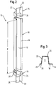
- Fig. 2 the handle insert 10 is the Fig. 1 enlarged and shown in exploded view.
- a middle part 16 of length d can be seen, which is designed as a plastic part with a constant profile, so that different middle parts 16 with different lengths d can be produced in a simple manner from a longer profile piece.
- the profile is essentially U-shaped, so that a recessed grip 12 is formed.
- the middle part 16 closes with a cladding section 18, which, in particular in the case of an insulated door of a refrigerator, closes the interior of the door, which is filled with insulating material, from the outside.
- the upper end piece 14 is designed as a plastic injection-molded part, which can be seen from the seam 22.
- the end piece 14 has a cover section 20 lying on the same plane as the trim section 18.
- the end 24 of the recessed grip 12 is molded into the end piece on the side facing the central part 16.
- the area 24 is thus closed as an upward, downward one however, an open depression is formed, the cross section of which is adapted to the cross section of the profile of the central part 16.
- the lower middle piece 15 is formed mirror-inverted to the end piece 14, which is why the same reference symbols are used to designate the corresponding sections.
- a flange 26 is visible at the lower end piece 15, which runs around the edge of the recessed grip end 24.
- a groove or another shape is preferably introduced, which allows an attachment or another type of positive or non-positive fastening of the middle part 18 to the end piece 15 and on the other side in the end piece 14.
- Fig. 3 shows a cross section through the central part 16 in an enlarged view.
- the essentially U-shaped section 30, which forms the recessed grip 12 is visible. As shown, this can be trapezoidal, but also rectangular or rounded.
- the cover section 18 is arranged on one side and a narrower section 28 on the other side.
- elongated projections 19, 29 can be arranged at the outer ends of these sections, which can serve to engage behind a correspondingly folded-off section of the door panel 5 or the inner shell of the door 2.
- the middle part 16 can also be held on the side cheek in any other way, for. B. by gluing or any positive or non-positive connection.
- a handle insert 10a or 10b is arranged on both the right and left side cheeks of a door 2.
- These handle inserts 10a and 10b are mirror-inverted to each other. However, they each contain the same middle piece 16 and the same end pieces 14, 15.
- the end piece 14, which is arranged on the right side cheek arranged handle insert 10a above is arranged below on the left hand side handle insert 10b.
- the end piece 15 arranged at the bottom on the right side cheek 8a is arranged at the top on the left side cheek 8b.
- the three different components used here can be colored differently, e.g. B. the middle parts 16 colored yellow, the first end piece 14 blue and the second end piece 15 may be colored orange, any other color combination, including metallic colors, being of course also possible.
- the end pieces 14, 15 are produced with two different injection molding tools on the inside simultaneously or successively by steps 31, 32.
- Each of the end pieces 14, 15 can also be multi-part in itself, so that further injection molds may be necessary.
- the end pieces 14, 15 can also have the same shape, so that only a single injection molding machine train is required.
- a handle insert with a first length is produced from two end pieces 14, 15 and a middle part with the length A.
- handle inserts with a second length B are each produced from two end pieces 14, 15 and a middle part with the length B.
- the method allows the production of handle inserts of different lengths in a simple manner, which can be used in different household appliances.
- These pre-assembled handle inserts are then integrated into the side cheek of a door, e.g. B. mounted in a portion of a door panel 5.
Description
Die Erfindung betrifft eine Tür für ein Haushaltsgerät, insbesondere für ein Haushaltskältegerät, wobei in zumindest eine Seitenwange der Tür ein Griffeinsatz integriert ist. Die Erfindung ist auch auf ein entsprechendes Haushaltsgerät sowie auf ein Verfahren zur Herstellung eines Griffeinsatzes gerichtet.The invention relates to a door for a household appliance, in particular for a household refrigerator, a handle insert being integrated in at least one side cheek of the door. The invention is also directed to a corresponding household appliance and to a method for producing a handle insert.
Es sind verschiedene Arten von Griffen für die Türen von Haushaltsgeräten bekannt. Zum einen ist es möglich, Türgriffe auf die Außenseite der Tür aufzusetzen. Hierbei werden die Griffe oft durch unterschiedlich lange Griffstangen gebildet, die zwischen zwei Lagerböcken montiert werden. Da bei den meisten Haushaltsgeräten die Wahl besteht, die Tür entweder links oder rechts an den Korpus anzuschlagen, werden oft Lösungen gewählt, bei denen die Griffe wahlweise rechts oder links an der Tür befestigt werden können.Various types of handles for the doors of household appliances are known. On the one hand, it is possible to place door handles on the outside of the door. The handles are often formed by handle bars of different lengths, which are mounted between two pedestals. Since most household appliances have the choice of hinging the door either on the left or right of the body, solutions are often chosen in which the handles can be attached to the door either on the right or left.
Insbesondere bei Kühlschränken ist ferner ein Konzept bekannt, bei dem in die obere Seitenwange der Tür eine Griffmulde integriert ist. Dies hat den Vorteil, dass das Haushaltsgerät eine ästhetisch anspruchsvolle, grifflose Front aufweist. Eine derartige Griffmulde wird durch ein einteiliges Kunststoffteil gebildet, welches an der Seitenwange zwischen das äußere Türblech und die Türinnenschale eingesetzt wird. Diese Lösung hat jedoch den Nachteil, dass für Haushaltsgeräte verschiedener Größe jeweils ein eigenes Kunststoffteil bereitgestellt werden muss.In the case of refrigerators in particular, a concept is also known in which a recessed grip is integrated in the upper side cheek of the door. This has the advantage that the household appliance has an aesthetically sophisticated, handle-less front. Such a recessed grip is formed by a one-piece plastic part which is inserted on the side cheek between the outer door panel and the inner door shell. However, this solution has the disadvantage that a separate plastic part must be provided for household appliances of different sizes.
Die Offenlegungsschrift
Die Offenlegungsschrift
Die Gebrauchsmusterschrift
Die Erfindung hat sich daher die Aufgabe gesetzt, eine Tür für ein Haushaltsgerät mit einem Griffeinsatz bereitzustellen, der besonders kostengünstig herstellbar ist. Darüber hinaus ist es eine Aufgabe der Einfindung, ein Griffkonzept zu entwickeln, welches für eine Serie verschiedener Haushaltsgeräte verwendet werden kann, um dadurch besonders kosteneffizient zu sein.The object of the invention is therefore to provide a door for a household appliance with a handle insert which can be produced particularly cost-effectively. In addition, it is a task of the inventor to develop a handle concept which can be used for a series of different household appliances, in order to be particularly cost-efficient.
Diese Aufgabe wird durch eine Tür mit einem in eine Seitenwange integrierten Griffeinsatz gelöst, wobei der Griffeinsatz in Längsrichtung der Seitenwange in zumindest zwei Teile unterteilt ist. Dadurch kann ein Teil identisch für verschiedene Geräte verwendet werden, während das andere Teil ausgetauscht wird, insbesondere in verschiedenen Längen hergestellt wird. Dadurch werden Herstellungskosten gespart. Erfindungsgemäß ist der Griffeinsatz dabei in Längsrichtung der Seitenwange in drei Teile unterteilt. Dies bietet den Vorteil, dass unterschiedlichste Längenvarianten dargestellt werden, indem ein oder mehrere der Teile identisch für verschiedene Geräte verwendet werden, während andere Teile ausgetauscht werden, insbesondere in verschiedenen Längen verwendet werden. Dadurch können Teile des Griffeinsatzes für Türen unterschiedlicher Höhe oder Breite verwendet werden.This object is achieved by a door with a handle insert integrated into a side cheek, the handle insert being divided into at least two parts in the longitudinal direction of the side cheek. As a result, one part can be used identically for different devices, while the other part is exchanged, in particular in different lengths. This saves manufacturing costs. According to the invention, the handle insert is divided into three parts in the longitudinal direction of the side cheek. This offers the advantage that the most varied length variants are represented, in that one or more of the parts are used identically for different devices, while other parts are exchanged, in particular in different lengths. This allows parts of the handle insert to be used for doors of different heights or widths.
Mit einer "Seitenwange" ist eine der vier Schmalseiten der Tür gemeint, welche jeweils zwischen der Außen- bzw. Frontseite und der Innenseite der Tür liegen. Die Erfindung kann sowohl auf eine obere oder untere Seitenwange als auch auf eine oder beide der seitlichen Seitenwangen angewendet werden.A "side wall" means one of the four narrow sides of the door, which are located between the outside or front and the inside of the door. The invention can be applied to an upper or lower side cheek as well as to one or both of the side side cheeks.
Besonders bevorzugt handelt es sich um die Tür eines Haushaltkältegeräts, z. B. eines Kühlschranks, eines Gefrierschranks, eines Weinschranks oder einer Kühl-Gefrierkombination. Insbesondere bei Geräten, die bis oberhalb der Arbeitsplatte einer Küche reichen, ist der erfindungsgemäße Griffeinsatz vorzugsweise in eine oder beide seitliche Seitenwangen der Tür integriert. Bei Geräten, die auf dem Boden stehen und nur etwa bis zur Höhe der Arbeitsplatte reichen, ist dagegen bevorzugt, dass der Griffeinsatz in die obere Seitenwange der Tür integriert ist.It is particularly preferably the door of a household refrigeration device, e.g. B. a refrigerator, a freezer, a wine cabinet or a fridge-freezer. In particular in the case of devices which reach above the worktop of a kitchen, the handle insert according to the invention is preferably integrated in one or both side cheeks of the door. For devices that are on the floor and only reach up to the height of the worktop, it is preferred that the handle insert is integrated in the upper side wall of the door.
Erfindungsgemäß ist der Griffeinsatz aus zumindest einem Mittelteil und zumindest zwei Endstücken zusammengesetzt. Dies weist den Vorteil auf, dass die beiden Endstücke jeweils für verschiedene Haushaltsgeräte verwendet werden können, während das Mittelteil für verschiedene Gerätetypen ausgetauscht wird. Insbesondere ist es vorteilhaft, das Mittelteil als ein Profilstück auszubilden, welches bei verschiedenen Gerätetypen in unterschiedlichen Längen verwendet wird. Es sind auch Ausführungsformen von der Erfindung umfasst, bei denen mehrere Mittelteile vorhanden sind. Darüber hinaus kann der Griffeinsatz auch mehr als zwei Endstücke aufweisen, z. B. indem jedes Ende des Griffeinsatzes von mehreren Endstücken gebildet wird. Ein Griffeinsatz kann an seinen beiden Enden jeweils zwei formgleiche Endstücke oder zwei unterschiedliche Endstücke aufweisen.According to the invention, the handle insert is composed of at least one middle part and at least two end pieces. This has the advantage that the two end pieces can each be used for different household appliances, while the middle part is exchanged for different types of devices. In particular, it is advantageous to design the middle part as a profile piece, which is used in different device types in different lengths. Embodiments are also encompassed by the invention in which a plurality of middle parts are present. In addition, the handle insert can also have more than two end pieces, for. B. by forming each end of the handle insert from a plurality of end pieces. A handle insert can have two end pieces of the same shape or two different end pieces at both ends.
Bei einer Ausführungsform der Erfindung weist der Griffeinsatz eine Griffmulde auf, also eine sich im Allgemeinen in Längsrichtung der Seitenwange erstreckende Vertiefung, in die der Benutzer beim Öffnen der Tür eingreift. Alternativ kann der Griffeinsatz jedoch auch ein herausstehendes Teil oder eine andere Art von Ausformung aufweisen, welche als Griff zum Öffnen der Tür geeignet ist.In one embodiment of the invention, the handle insert has a recessed grip, that is to say a depression which extends generally in the longitudinal direction of the side cheek and into which the user engages when the door is opened. Alternatively, however, the handle insert can also have a protruding part or another type of shape which is suitable as a handle for opening the door.
Vorzugsweise sind die Teile des Griffeinsatzes aus Kunststoff hergestellt, beispielsweise PE oder ein anderer spritzgussfähiger und besonders bevorzugt zusätzlich extrudierfähiger Kunststoff. Alternativ können die Teile jedoch auch aus Gummi oder Metallblech gefertigt sein.The parts of the handle insert are preferably made of plastic, for example PE or another injection-moldable and particularly preferably additionally extrudable plastic. Alternatively, however, the parts can also be made of rubber or sheet metal.
Besonders bevorzugt sind die Endstücke des Griffeinsatzes als Kunststoff-Spritzgussteile ausgestaltet. Dies erlaubt eine kostengünstige Herstellung bei gleichzeitiger freier Formenwahl. Das Mittelteil ist dagegen erfindungsgemäß als Extrusionsprofil ausgestaltet. Dies bietet den Vorteil, dass das Mittelteil als Endlosprodukt hergestellt werden kann und dann durch Ablängen des Extrusionsprofils auf einfache Weise Mittelteile mit unterschiedlichen Längen hergestellt werden können. Vorzugsweise können die beiden Endstücke bei jeder Längenvariante eingesetzt werden. Dies bedeutet ein großes Einsparpotential bei den Spritzgusswerkzeugen, da bei der bekannten Lösung für jede Länge ein extra Spritzgießwerkzeug gefertigt werden musste. Bei dieser Ausführungsform werden dagegen nur ein oder gegebenenfalls zwei Spritzgießwerkzeuge und ein Extrusionswerkzeug benötigt. Auch das als Extrusionsprofil ausgestaltete Mittelteil besteht bevorzugt aus Kunststoff.The end pieces of the handle insert are particularly preferably configured as plastic injection molded parts. This allows cost-effective production with simultaneous free choice of shape. In contrast, the middle part is designed according to the invention as an extrusion profile. This offers the advantage that the middle part can be produced as an endless product and then middle parts with different lengths can be produced in a simple manner by cutting the extrusion profile to length. The two end pieces can preferably be used in any length variant. This means a great savings potential with the injection molding tools, since with the known solution an extra injection molding tool had to be manufactured for each length. In this embodiment, on the other hand, only one or possibly two injection molding tools are used and needed an extrusion tool. The central part designed as an extrusion profile also preferably consists of plastic.
Besonders bevorzugt ist in beide seitlichen Seitenwangen der Tür jeweils ein Griffeinsatz integriert. Die beiden Griffeinsätze weisen bevorzugt die gleiche Länge auf und sind vorzugsweise spiegelbildlich zueinander ausgestaltet. Dies kann besonders vorteilhaft dadurch erreicht werden, dass die beiden Griffeinsätze jeweils aus den gleichen Endstücken und den gleichen Mittelteilen aufgebaut sind, wobei das auf der linken Seitenwange oben angeordnete Endstück auf der rechten Seitenwange unten angeordnet ist und vice versa, d. h. das auf der linken Seitenwange unten angeordnete Endstück ist auf der rechten Seitenwange oben angeordnet. Somit werden für die beiden Griffeinsätze zwei gleichartige Mittelteile, zwei gleichartige erste Endstücke und zwei gleichartige zweite Endstücke benötigt, wobei ein erstes und ein zweites Endstück bevorzugt spiegelverkehrt zueinander aufgebaut sind. Durch Integrieren eines Griffeinsatzes in jede der beiden seitlichen Seitenwangen wird ermöglicht, die Tür wahlweise rechts oder links an das Haushaltsgerät anzuschlagen.A handle insert is particularly preferably integrated in each of the two side cheeks of the door. The two handle inserts preferably have the same length and are preferably designed as mirror images of one another. This can be achieved particularly advantageously in that the two handle inserts are each constructed from the same end pieces and the same middle parts, the end piece arranged on the left side cheek at the top being arranged on the right side cheek at the bottom and vice versa, ie that on the left side cheek end piece located at the bottom is located on the right side cheek at the top. Thus, two identical middle parts, two identical first end pieces and two identical second end pieces are required for the two handle inserts, a first and a second end piece preferably being constructed mirror-inverted to one another. By integrating a handle insert into each of the two side cheeks enables the door to be hinged on the right or left of the household appliance.
Bei einer Ausführungsform der Erfindung ist die Außenseite der Tür aus einem Türblech gefertigt, z. B. aus einem Metallblech aus Aluminium oder Stahl. Derartige Türbleche bilden eine ästhetisch ansprechende Frontseite der Tür. An den Seitenwangen kann das Türblech nach innen umgebogen sein, um die Seitenwangen zu bilden. Der Griffeinsatz ist dann jeweils in einen Ausschnitt in der Seitenwange eingesetzt. Alternativ kann die Seitenwange auch komplett oder teilweise von dem Griffeinsatz gebildet werden. Dieser ist dann z. B. formschlüssig, kraftschlüssig oder stoffschlüssig, z. B. durch Kleben an dem Türblech befestigt. Vorzugsweise ist der Griffeinsatz formschlüssig in der Seitenwange der Tür gehaltert, z. B. durch einen Rast-, Klemm- oder Steckmechanismus. Alternativ kann der Griffeinsatz auch durch Kleben oder Einschäumen des Zwischenraums zwischen Außenseite und Innenschale der Tür in der Seitenwange gehaltert sein.In one embodiment of the invention, the outside of the door is made from a door panel, e.g. B. from a metal sheet made of aluminum or steel. Such door panels form an aesthetically pleasing front of the door. On the side panels, the door panel can be bent inwards to form the side panels. The handle insert is then inserted into a cutout in the side cheek. Alternatively, the side cheek can also be formed entirely or partially by the handle insert. This is then z. B. positive, non-positive or material, z. B. attached by gluing to the door panel. Preferably, the handle insert is positively held in the side cheek of the door, e.g. B. by a locking, clamping or plug-in mechanism. Alternatively, the handle insert can also be held in the side cheek by gluing or foaming the space between the outside and the inner shell of the door.
Die einzelnen Teile des Griffeinsatzes können bevorzugt form-, stoff- oder kraftschlüssig aneinander befestigt werden, insbesondere mittels einer Rast-, Klemm- oder Steckverbindung.The individual parts of the handle insert can preferably be fastened to one another in a form-fitting, material-locking or non-positive manner, in particular by means of a latching, clamping or plug connection.
Durch die Mehrteiligkeit des Griffeinsatzes bieten sich auch für das Design Vorteile. Insbesondere können die einzelnen Teile des Griffeinsatzes farblich voneinander abgesetzt werden, z. B. können die beiden Endstücke mit einer anderen Farbe als das Mittelteil hergestellt werden. Für die Montage bietet es sich darüber hinaus an, falls zwei verschiedene Endstücke verwendet werden, diese farblich unterschiedlich zu gestalten, damit sie bei der Montage leicht auseinandergehalten werden können.The multi-part design of the handle insert also offers advantages for the design. In particular, the individual parts of the handle insert can be contrasted in color, z. B. the two end pieces can be made with a different color than the central part. For the assembly, it is also advisable, if two different end pieces are used, to design them in different colors so that they can be easily separated during assembly.
Darüber hinaus ist die Erfindung auch auf ein mit einer entsprechenden Tür ausgestaltetes Haushaltsgerät gerichtet.In addition, the invention is also directed to a household appliance designed with a corresponding door.
Darüber hinaus wird die Aufgabe der Erfindung auch durch ein Verfahren zur Herstellung eines Griffeinsatzes zum Einsetzen in die Seitenwange einer Tür eines Haushaltsgerätes gelöst, wobei der Griffeinsatz aus zumindest einem Mittelteil und zumindest zwei Endstücken zusammengesetzt ist. Das Verfahren beinhaltet die folgenden Schritte: (a) Spritzgießen der Endstücke des Griffeinsatzes, (b) Extrudieren eines Extrusionsprofils, (c) Ablängen des Extrusionsprofils zur Herstellung eines Mittelteils, und (d) Zusammensetzen der Endstücke und des Mittelteils zu einem Griffeinsatz. Letzteres geschieht z. B. durch Stecken der Endstücke von oben und unten auf das Mittelteil. Durch Ablängen des Extrusionsprofils zu unterschiedlich langen Mittelteilen können somit auf einfache Weise unterschiedlich lange Griffeinsätze hergestellt werden.In addition, the object of the invention is also achieved by a method for producing a handle insert for insertion into the side cheek of a door of a household appliance, the handle insert being composed of at least one middle part and at least two end pieces. The process includes the following steps: (a) injection molding the end pieces of the handle insert, (b) extruding an extrusion profile, (c) cutting to length the extrusion profile for producing a middle part, and (d) assembling the end pieces and the middle part into a handle insert. The latter happens for. B. by inserting the end pieces from above and below on the middle part. By cutting the extrusion profile to different lengths of middle parts, handle inserts of different lengths can thus be produced in a simple manner.
Bei einer Ausführungsform, bei der jeder Griffeinsatz an jedem Ende ein Endstück aufweist, können die beiden Endstücke entweder exakt die gleiche Form ausweisen, so dass sie im gleichen Spritzgießwerkzeug gegossen werden können. Alternativ können die Endstücke unterschiedlich ausgestaltet sein, z. B. unterschiedlich lang und/oder spiegelverkehrt, so dass sie in jeweils unterschiedlichen Spritzgießwerkzeugen gegossen werden. Das Extrusionsprofil ist z. B. im Wesentlichen U-förmig, um dadurch eine Griffmulde im Mittelteil auszubilden.In one embodiment, in which each handle insert has an end piece at each end, the two end pieces can either have exactly the same shape, so that they can be molded in the same injection mold. Alternatively, the end pieces can be designed differently, e.g. B. of different lengths and / or mirror-inverted, so that they are cast in different injection molds. The extrusion profile is e.g. B. substantially U-shaped to thereby form a recessed grip in the middle part.
Mit diesem Verfahren kann bevorzugt ein Griffeinsatz wie oben beschriebenen hergestellt werden.With this method, a handle insert as described above can preferably be produced.
Die Erfindung wird nun anhand eines Ausführungsbeispiels mit Bezug auf die beiliegenden Zeichnungen näher erläutert. In den Zeichnungen zeigen:
- Fig. 1
- ein Kältegerät mit einer Tür gemäß einem Ausführungsbeispiel der Erfindung in einer perspektivischen Ansicht;
- Fig. 2
- eine perspektivische Explosionsansicht eines Griffeinsatzes;
- Fig. 3
- das Mittelteil des Griffeinsatzes der
Fig. 2 im Querschnitt; - Fig. 4
- eine perspektivische Ansicht auf zwei Griffeinsätze, die in eine linke und eine rechte Seitenwange einer Tür integriert sind;
- Fig. 5
- eine schematische Darstellung eines Ausführungsbeispiels des erfindungsgemäßen Verfahrens.
- Fig. 1
- a refrigerator with a door according to an embodiment of the invention in a perspective view;
- Fig. 2
- an exploded perspective view of a handle insert;
- Fig. 3
- the middle part of the handle insert
Fig. 2 in cross section; - Fig. 4
- a perspective view of two handle inserts, which are integrated into a left and a right side cheek of a door;
- Fig. 5
- is a schematic representation of an embodiment of the method according to the invention.
In
Dabei ist ein Mittelteil 16 der Länge d zu erkennen, welches als ein Kunststoffteil mit konstantem Profil ausgestaltet ist, so dass auf einfache Weise aus einem längeren Profilstück verschiedene Mittelteile 16 mit verschiedenen Längen d hergestellt werden können. Das Profil ist im Wesentlichen U-förmig, so dass eine Griffmulde 12 ausgebildet wird. Nach hinten, d. h. zum Korpus 3 des Haushaltsgeräts hin, schließt das Mittelteil 16 mit einem Verkleidungsabschnitt 18 ab, welcher, insbesondere bei einer isolierten Tür eines Kältegerätes, den Innenraum der Tür, der mit Isoliermaterial gefüllt ist, nach außen verschließt.A
Das obere Endstück 14 ist in diesem Ausführungsbeispiel als Kunststoff-Spritzgussteil ausgestaltet, was an der Naht 22 zu erkennen ist. Das Endstück 14 weist einen auf gleicher Ebene mit dem Verkleidungsabschnitt 18 liegenden Abdeckungsabschnitt 20 auf. Auf der dem Mittelteil 16 zugewandten Seite ist der Abschluss 24 der Griffmulde 12 in das Endstück eingeformt. Der Bereich 24 ist also als eine nach oben geschlossene, nach unten jedoch offene Vertiefung ausgeformt, deren Querschnitt dem Querschnitt des Profils des Mittelteils 16 angepasst ist.In this exemplary embodiment, the
Das untere Mittelstück 15 ist in diesem Fall spiegelverkehrt zu dem Endstück 14 gebildet, weshalb die gleichen Bezugszeichen zur Bezeichnung der entsprechenden Abschnitte verwendet werden. Darüber hinaus ist beim unteren Endstück 15 ein Flansch 26 sichtbar, der den Rand des Griffmuldenabschlusses 24 umläuft. In diesen Flansch 26 ist vorzugsweise eine Nut oder eine andere Form eingebracht, die ein Aufstecken bzw. eine andere Art der form- oder kraftschlüssigen Befestigung des Mittelteils 18 an dem Endstück 15 und auf der anderen Seite im Endstück 14 erlaubt.In this case, the lower
Anhand der
Die hier verwendeten drei unterschiedlichen Bauteile können unterschiedlich eingefärbt sein, z. B. können die Mittelteile 16 gelb gefärbt, das erste Endstück 14 blau und das zweite Endstück 15 orange eingefärbt sein, wobei jede andere Farbkombination, einschließlich Metallicfarben selbstverständlich auch möglich ist.The three different components used here can be colored differently, e.g. B. the
Anhand der
In Schritt 36 werden jeweils aus zwei Endstücken 14, 15 und einem Mittelteil mit der Länge A ein Griffeinsatz mit einer ersten Länge hergestellt. In Schritt 37 werden Griffeinsätze mit einer zweiten Länge B jeweils aus zwei Endstücken 14, 15 und einem Mittelteil mit der Länge B hergestellt. Auf diese Weise erlaubt das Verfahren auf einfache Weise die Herstellung von Griffeinsätzen unterschiedlicher Länge, die bei verschiedenen Haushaltsgeräten zum Einsatz kommen können. Dieser derart vormontierten Griffeinsätze werden dann in die Seitenwange einer Tür integriert, z. B. in einen Abschnitt eines Türblechs 5 montiert.In
- 11
- Haushaltsgeräthousehold appliance
- 22
- Türdoor
- 33
- Korpuscorpus
- 55
- Türblechdoor panel
- 6a, 6b6a, 6b
- Schwenkgelenkeswivel joints
- 8a, 8b8a, 8b
- rechte und linke Seitenwangeright and left side cheek
- 9a, 9b9a, 9b
- untere und obere Seitenwange der Türlower and upper side cheek of the door
- 1010
- Griffeinsatzhandle insert
- 1212
- Griffmuldegrip
- 1414
- oberes Endstück des Griffeinsatzesupper end of the handle insert
- 1515
- unteres Endstück des Griffeinsatzeslower end of the handle insert
- 1616
- Mittelteil des GriffeinsatzesMiddle part of the handle insert
- 1717
- Verkleidungpaneling
- 1818
- Abdeckungsabschnittcover portion
- 2020
- Abdeckungsabschnittcover portion
- 2222
- Spritzgussnahtinjection seam
- 2424
- Abschluss der GriffmuldeCompletion of the recessed grip
- 2626
- Flanschflange
- 1919
- wulstförmiger Vorsprungbeaded projection
- 2828
- Abdeckungsabschnittcover portion
- 2929
- wulstförmiger Vorsprungbeaded projection
- 3030
- U-ProfilabschnittU-profile section
- 31 - 3731-37
- Verfahrensschrittesteps
Claims (13)
- Door (2) for a household appliance (1), in particular for a household refrigeration appliance, wherein a handle insert (10) is integrated into a least one side wall (8a, 8b) of the door, wherein the handle insert (100) is divided into at least three parts (14, 15, 16) in the longitudinal direction of the side walls, wherein the handle insert (10) is assembled from at least one central part (16) and at least two end pieces (14, 15), characterised in that the at least one central part (16) of the handle insert is designed as a piece of an extrusion profile.
- Door according to one of the preceding claims, characterised in that the handle insert (10) has a recessed grip (12).
- Door according to one of the preceding claims, characterised in that the parts (14, 15, 16) of the handle insert (10) are produced from plastic.
- Door according to one of the preceding claims, characterised in that the end pieces (14, 15) of the handle insert (10) are designed as plastic injection moulded parts.
- Door according to one of the preceding claims, characterised in that a handle insert (10a, 10b) is integrated into both lateral side walls (8a, 8b) of the door.
- Door according to claim 5, characterised in that the handle inserts (10a, 10b) integrated into the two lateral side walls (8a, 8b) of the door (2) are each built from the same end pieces (14, 15) and the same central parts (16), wherein the end piece (15) arranged above on the left side wall is arranged below on the right side wall and vice versa.
- Door according to one of the preceding claims, characterised in that the exterior of the door (2) is manufactured from a door panel (5).
- Door according to one of the preceding claims, characterised in that the handle insert (10) is held in a form-fit manner in the side wall (8a, 8b) of the door.
- Door according to one of the preceding claims, characterised in that the individual parts (14, 15, 16) of the handle insert (10) are designed to be different colours.
- Household appliance (1), in particular refrigerator or deep freezer, equipped with a door (2) according to one of the preceding claims.
- Method for producing a handle insert (10) for insertion into the side wall (8a, 8b) of a door (2) of a household appliance (1) according to one of the preceding claims 1-10, in particular of a household refrigeration appliance, wherein the handle insert is assembled from at least one central part (16) and at least two end pieces (14, 15), characterised by the following steps:a) injection moulding (31, 32) the end pieces (14, 15) of the handle insert;b) extruding (34) an extrusion profile;c) trimming (35) the extrusion profile in order to produce a central part (16); andd) assembling the end pieces and the central part to form a handle insert (10).
- Method according to claim 11, characterised in that the handle insert (10) has two end pieces (14, 15) which are cast in different injection moulding tools in each case.
- Method according to claim 11 or 12, characterised in that the handle insert is designed according to one of claims 1 to 10.
Applications Claiming Priority (2)
| Application Number | Priority Date | Filing Date | Title |
|---|---|---|---|
| DE102009028786A DE102009028786A1 (en) | 2009-08-21 | 2009-08-21 | Door for a household appliance with handle insert |
| PCT/EP2010/061871 WO2011020804A2 (en) | 2009-08-21 | 2010-08-16 | Door for a household appliance having a handle insert |
Publications (2)
| Publication Number | Publication Date |
|---|---|
| EP2467657A2 EP2467657A2 (en) | 2012-06-27 |
| EP2467657B1 true EP2467657B1 (en) | 2020-02-12 |
Family
ID=43495247
Family Applications (1)
| Application Number | Title | Priority Date | Filing Date |
|---|---|---|---|
| EP10743125.6A Active EP2467657B1 (en) | 2009-08-21 | 2010-08-16 | Door for a household appliance having a handle insert |
Country Status (3)
| Country | Link |
|---|---|
| EP (1) | EP2467657B1 (en) |
| DE (1) | DE102009028786A1 (en) |
| WO (1) | WO2011020804A2 (en) |
Cited By (2)
| Publication number | Priority date | Publication date | Assignee | Title |
|---|---|---|---|---|
| EP3992555A1 (en) * | 2020-11-03 | 2022-05-04 | BSH Hausgeräte GmbH | Door with a specifically coloured recessed grip on an edge side of the door, and domestic appliance and method |
| DE102021125085A1 (en) | 2021-09-28 | 2023-03-30 | Liebherr-Hausgeräte Marica EOOD | Door for a refrigerator and/or freezer |
Families Citing this family (3)
| Publication number | Priority date | Publication date | Assignee | Title |
|---|---|---|---|---|
| DE102011014285A1 (en) * | 2011-03-17 | 2012-09-20 | BSH Bosch und Siemens Hausgeräte GmbH | Door, in particular for a refrigeration device |
| DE102015221885A1 (en) * | 2015-11-06 | 2017-05-24 | BSH Hausgeräte GmbH | Door with a door frame and a handle recess element and household refrigeration appliance with such a door |
| DE102020208158A1 (en) * | 2020-06-30 | 2021-12-30 | BSH Hausgeräte GmbH | Household appliance with a closure element and a specifically shaped recessed grip on a narrow side of the closure element |
Citations (1)
| Publication number | Priority date | Publication date | Assignee | Title |
|---|---|---|---|---|
| WO2004048723A1 (en) * | 2002-11-25 | 2004-06-10 | Multibrás S.A. Eletrodomésticos | Handle arrangement for the front door of cabinets |
Family Cites Families (3)
| Publication number | Priority date | Publication date | Assignee | Title |
|---|---|---|---|---|
| FR1367611A (en) * | 1963-06-11 | 1964-07-24 | Thomson Houston Comp Francaise | Improvements to refrigerator doors |
| DE202006002458U1 (en) * | 2006-02-16 | 2007-06-28 | Liebherr-Hausgeräte Lienz Gmbh | Refrigerator and freezer door, has profile bead on which handle is mounted, where position of handle is selectable along profile bead, and fastening unit is inserted into profile bead |
| DE102007055174A1 (en) * | 2007-11-19 | 2009-05-20 | BSH Bosch und Siemens Hausgeräte GmbH | Door for a refrigeration appliance |
-
2009
- 2009-08-21 DE DE102009028786A patent/DE102009028786A1/en not_active Withdrawn
-
2010
- 2010-08-16 WO PCT/EP2010/061871 patent/WO2011020804A2/en active Application Filing
- 2010-08-16 EP EP10743125.6A patent/EP2467657B1/en active Active
Patent Citations (1)
| Publication number | Priority date | Publication date | Assignee | Title |
|---|---|---|---|---|
| WO2004048723A1 (en) * | 2002-11-25 | 2004-06-10 | Multibrás S.A. Eletrodomésticos | Handle arrangement for the front door of cabinets |
Cited By (2)
| Publication number | Priority date | Publication date | Assignee | Title |
|---|---|---|---|---|
| EP3992555A1 (en) * | 2020-11-03 | 2022-05-04 | BSH Hausgeräte GmbH | Door with a specifically coloured recessed grip on an edge side of the door, and domestic appliance and method |
| DE102021125085A1 (en) | 2021-09-28 | 2023-03-30 | Liebherr-Hausgeräte Marica EOOD | Door for a refrigerator and/or freezer |
Also Published As
| Publication number | Publication date |
|---|---|
| WO2011020804A2 (en) | 2011-02-24 |
| WO2011020804A3 (en) | 2011-05-26 |
| EP2467657A2 (en) | 2012-06-27 |
| DE102009028786A1 (en) | 2011-02-24 |
Similar Documents
| Publication | Publication Date | Title |
|---|---|---|
| EP2235451B1 (en) | Storage container for a refrigerating device | |
| DE102005037891B4 (en) | Door handle for a refrigerator | |
| EP2467657B1 (en) | Door for a household appliance having a handle insert | |
| EP1599113B1 (en) | Door handle | |
| WO2012139950A2 (en) | Set of parts for a refrigerator door | |
| DE102008063390A1 (en) | Refrigerating appliance with a shelf | |
| EP1397628A1 (en) | Refrigerated-goods container for a refrigeration device | |
| DE202010002446U1 (en) | Roof rack arrangement | |
| DE202008005350U1 (en) | Storage container for a refrigeration device | |
| DE10131829A1 (en) | Slidable sun visor for a sun roof of a motor vehicle | |
| EP2457042B1 (en) | Domestic refrigeration appliance with a shelf, shelf and method for producing a shelf | |
| WO2011124446A2 (en) | Door shelf for a refrigerator | |
| WO2011009780A2 (en) | Door for a heat-insulating housing | |
| DE10259749A1 (en) | Refrigeration device and door for a refrigeration device | |
| EP2464928B1 (en) | Refrigerator | |
| EP2023063A2 (en) | Door frame closing element of a household device door | |
| EP1095232A1 (en) | Storage compartment | |
| DE102005011077A1 (en) | Vehicle door comprises an inner sheet metal section with penetrations, a plastic carrier section sprayed onto it, and an actuating unit | |
| DE10208063A1 (en) | Method for manufacturing door mounted storage containers for refrigerators is assembled from common parts and consistent section walls of various lengths | |
| DE19654048C2 (en) | Double-walled container with an inner wall and an outer wall made of a thermally highly conductive material, in particular for refrigerators and heating cabinets | |
| WO2012123245A2 (en) | Door, in particular for a refrigerator | |
| DE102011007845A1 (en) | Diaphragm for covering and/or fixing part of e.g. display window of dishwasher, has end caps partially or completely covering front-side ends of decoration part that includes fastening unit and profile with two legs | |
| EP2281159A1 (en) | Door for a household appliance | |
| WO2005023065A1 (en) | Boxes for keys | |
| DE10330069A1 (en) | Handle for kitchen cupboards and drawers is made up of bar, which acts as grip, and strip with trapezium-shaped cross-section, which acts as mounting |
Legal Events
| Date | Code | Title | Description |
|---|---|---|---|
| PUAI | Public reference made under article 153(3) epc to a published international application that has entered the european phase |
Free format text: ORIGINAL CODE: 0009012 |
|
| 17P | Request for examination filed |
Effective date: 20120321 |
|
| AK | Designated contracting states |
Kind code of ref document: A2 Designated state(s): AL AT BE BG CH CY CZ DE DK EE ES FI FR GB GR HR HU IE IS IT LI LT LU LV MC MK MT NL NO PL PT RO SE SI SK SM TR |
|
| DAX | Request for extension of the european patent (deleted) | ||
| RAP1 | Party data changed (applicant data changed or rights of an application transferred) |
Owner name: BSH HAUSGERAETE GMBH |
|
| STAA | Information on the status of an ep patent application or granted ep patent |
Free format text: STATUS: EXAMINATION IS IN PROGRESS |
|
| 17Q | First examination report despatched |
Effective date: 20180329 |
|
| GRAP | Despatch of communication of intention to grant a patent |
Free format text: ORIGINAL CODE: EPIDOSNIGR1 |
|
| STAA | Information on the status of an ep patent application or granted ep patent |
Free format text: STATUS: GRANT OF PATENT IS INTENDED |
|
| INTG | Intention to grant announced |
Effective date: 20190917 |
|
| GRAS | Grant fee paid |
Free format text: ORIGINAL CODE: EPIDOSNIGR3 |
|
| GRAA | (expected) grant |
Free format text: ORIGINAL CODE: 0009210 |
|
| STAA | Information on the status of an ep patent application or granted ep patent |
Free format text: STATUS: THE PATENT HAS BEEN GRANTED |
|
| AK | Designated contracting states |
Kind code of ref document: B1 Designated state(s): AL AT BE BG CH CY CZ DE DK EE ES FI FR GB GR HR HU IE IS IT LI LT LU LV MC MK MT NL NO PL PT RO SE SI SK SM TR |
|
| REG | Reference to a national code |
Ref country code: GB Ref legal event code: FG4D Free format text: NOT ENGLISH |
|
| REG | Reference to a national code |
Ref country code: CH Ref legal event code: EP |
|
| REG | Reference to a national code |
Ref country code: AT Ref legal event code: REF Ref document number: 1232662 Country of ref document: AT Kind code of ref document: T Effective date: 20200215 |
|
| REG | Reference to a national code |
Ref country code: DE Ref legal event code: R096 Ref document number: 502010016481 Country of ref document: DE |
|
| REG | Reference to a national code |
Ref country code: IE Ref legal event code: FG4D Free format text: LANGUAGE OF EP DOCUMENT: GERMAN |
|
| PG25 | Lapsed in a contracting state [announced via postgrant information from national office to epo] |
Ref country code: FI Free format text: LAPSE BECAUSE OF FAILURE TO SUBMIT A TRANSLATION OF THE DESCRIPTION OR TO PAY THE FEE WITHIN THE PRESCRIBED TIME-LIMIT Effective date: 20200212 Ref country code: NO Free format text: LAPSE BECAUSE OF FAILURE TO SUBMIT A TRANSLATION OF THE DESCRIPTION OR TO PAY THE FEE WITHIN THE PRESCRIBED TIME-LIMIT Effective date: 20200512 |
|
| REG | Reference to a national code |
Ref country code: LT Ref legal event code: MG4D |
|
| REG | Reference to a national code |
Ref country code: NL Ref legal event code: MP Effective date: 20200212 |
|
| PG25 | Lapsed in a contracting state [announced via postgrant information from national office to epo] |
Ref country code: GR Free format text: LAPSE BECAUSE OF FAILURE TO SUBMIT A TRANSLATION OF THE DESCRIPTION OR TO PAY THE FEE WITHIN THE PRESCRIBED TIME-LIMIT Effective date: 20200513 Ref country code: BG Free format text: LAPSE BECAUSE OF FAILURE TO SUBMIT A TRANSLATION OF THE DESCRIPTION OR TO PAY THE FEE WITHIN THE PRESCRIBED TIME-LIMIT Effective date: 20200512 Ref country code: HR Free format text: LAPSE BECAUSE OF FAILURE TO SUBMIT A TRANSLATION OF THE DESCRIPTION OR TO PAY THE FEE WITHIN THE PRESCRIBED TIME-LIMIT Effective date: 20200212 Ref country code: IS Free format text: LAPSE BECAUSE OF FAILURE TO SUBMIT A TRANSLATION OF THE DESCRIPTION OR TO PAY THE FEE WITHIN THE PRESCRIBED TIME-LIMIT Effective date: 20200612 Ref country code: SE Free format text: LAPSE BECAUSE OF FAILURE TO SUBMIT A TRANSLATION OF THE DESCRIPTION OR TO PAY THE FEE WITHIN THE PRESCRIBED TIME-LIMIT Effective date: 20200212 Ref country code: LV Free format text: LAPSE BECAUSE OF FAILURE TO SUBMIT A TRANSLATION OF THE DESCRIPTION OR TO PAY THE FEE WITHIN THE PRESCRIBED TIME-LIMIT Effective date: 20200212 |
|
| PG25 | Lapsed in a contracting state [announced via postgrant information from national office to epo] |
Ref country code: NL Free format text: LAPSE BECAUSE OF FAILURE TO SUBMIT A TRANSLATION OF THE DESCRIPTION OR TO PAY THE FEE WITHIN THE PRESCRIBED TIME-LIMIT Effective date: 20200212 |
|
| PG25 | Lapsed in a contracting state [announced via postgrant information from national office to epo] |
Ref country code: ES Free format text: LAPSE BECAUSE OF FAILURE TO SUBMIT A TRANSLATION OF THE DESCRIPTION OR TO PAY THE FEE WITHIN THE PRESCRIBED TIME-LIMIT Effective date: 20200212 Ref country code: DK Free format text: LAPSE BECAUSE OF FAILURE TO SUBMIT A TRANSLATION OF THE DESCRIPTION OR TO PAY THE FEE WITHIN THE PRESCRIBED TIME-LIMIT Effective date: 20200212 Ref country code: EE Free format text: LAPSE BECAUSE OF FAILURE TO SUBMIT A TRANSLATION OF THE DESCRIPTION OR TO PAY THE FEE WITHIN THE PRESCRIBED TIME-LIMIT Effective date: 20200212 Ref country code: SM Free format text: LAPSE BECAUSE OF FAILURE TO SUBMIT A TRANSLATION OF THE DESCRIPTION OR TO PAY THE FEE WITHIN THE PRESCRIBED TIME-LIMIT Effective date: 20200212 Ref country code: RO Free format text: LAPSE BECAUSE OF FAILURE TO SUBMIT A TRANSLATION OF THE DESCRIPTION OR TO PAY THE FEE WITHIN THE PRESCRIBED TIME-LIMIT Effective date: 20200212 Ref country code: SK Free format text: LAPSE BECAUSE OF FAILURE TO SUBMIT A TRANSLATION OF THE DESCRIPTION OR TO PAY THE FEE WITHIN THE PRESCRIBED TIME-LIMIT Effective date: 20200212 Ref country code: CZ Free format text: LAPSE BECAUSE OF FAILURE TO SUBMIT A TRANSLATION OF THE DESCRIPTION OR TO PAY THE FEE WITHIN THE PRESCRIBED TIME-LIMIT Effective date: 20200212 Ref country code: LT Free format text: LAPSE BECAUSE OF FAILURE TO SUBMIT A TRANSLATION OF THE DESCRIPTION OR TO PAY THE FEE WITHIN THE PRESCRIBED TIME-LIMIT Effective date: 20200212 Ref country code: PT Free format text: LAPSE BECAUSE OF FAILURE TO SUBMIT A TRANSLATION OF THE DESCRIPTION OR TO PAY THE FEE WITHIN THE PRESCRIBED TIME-LIMIT Effective date: 20200705 |
|
| REG | Reference to a national code |
Ref country code: DE Ref legal event code: R097 Ref document number: 502010016481 Country of ref document: DE |
|
| PLBE | No opposition filed within time limit |
Free format text: ORIGINAL CODE: 0009261 |
|
| STAA | Information on the status of an ep patent application or granted ep patent |
Free format text: STATUS: NO OPPOSITION FILED WITHIN TIME LIMIT |
|
| 26N | No opposition filed |
Effective date: 20201113 |
|
| PG25 | Lapsed in a contracting state [announced via postgrant information from national office to epo] |
Ref country code: IT Free format text: LAPSE BECAUSE OF FAILURE TO SUBMIT A TRANSLATION OF THE DESCRIPTION OR TO PAY THE FEE WITHIN THE PRESCRIBED TIME-LIMIT Effective date: 20200212 |
|
| PG25 | Lapsed in a contracting state [announced via postgrant information from national office to epo] |
Ref country code: PL Free format text: LAPSE BECAUSE OF FAILURE TO SUBMIT A TRANSLATION OF THE DESCRIPTION OR TO PAY THE FEE WITHIN THE PRESCRIBED TIME-LIMIT Effective date: 20200212 Ref country code: SI Free format text: LAPSE BECAUSE OF FAILURE TO SUBMIT A TRANSLATION OF THE DESCRIPTION OR TO PAY THE FEE WITHIN THE PRESCRIBED TIME-LIMIT Effective date: 20200212 |
|
| PG25 | Lapsed in a contracting state [announced via postgrant information from national office to epo] |
Ref country code: MC Free format text: LAPSE BECAUSE OF FAILURE TO SUBMIT A TRANSLATION OF THE DESCRIPTION OR TO PAY THE FEE WITHIN THE PRESCRIBED TIME-LIMIT Effective date: 20200212 |
|
| REG | Reference to a national code |
Ref country code: CH Ref legal event code: PL |
|
| GBPC | Gb: european patent ceased through non-payment of renewal fee |
Effective date: 20200816 |
|
| PG25 | Lapsed in a contracting state [announced via postgrant information from national office to epo] |
Ref country code: LU Free format text: LAPSE BECAUSE OF NON-PAYMENT OF DUE FEES Effective date: 20200816 Ref country code: LI Free format text: LAPSE BECAUSE OF NON-PAYMENT OF DUE FEES Effective date: 20200831 Ref country code: CH Free format text: LAPSE BECAUSE OF NON-PAYMENT OF DUE FEES Effective date: 20200831 |
|
| REG | Reference to a national code |
Ref country code: BE Ref legal event code: MM Effective date: 20200831 |
|
| PG25 | Lapsed in a contracting state [announced via postgrant information from national office to epo] |
Ref country code: FR Free format text: LAPSE BECAUSE OF NON-PAYMENT OF DUE FEES Effective date: 20200831 |
|
| PG25 | Lapsed in a contracting state [announced via postgrant information from national office to epo] |
Ref country code: BE Free format text: LAPSE BECAUSE OF NON-PAYMENT OF DUE FEES Effective date: 20200831 Ref country code: GB Free format text: LAPSE BECAUSE OF NON-PAYMENT OF DUE FEES Effective date: 20200816 Ref country code: IE Free format text: LAPSE BECAUSE OF NON-PAYMENT OF DUE FEES Effective date: 20200816 |
|
| REG | Reference to a national code |
Ref country code: AT Ref legal event code: MM01 Ref document number: 1232662 Country of ref document: AT Kind code of ref document: T Effective date: 20200816 |
|
| PG25 | Lapsed in a contracting state [announced via postgrant information from national office to epo] |
Ref country code: AT Free format text: LAPSE BECAUSE OF NON-PAYMENT OF DUE FEES Effective date: 20200816 |
|
| PG25 | Lapsed in a contracting state [announced via postgrant information from national office to epo] |
Ref country code: TR Free format text: LAPSE BECAUSE OF FAILURE TO SUBMIT A TRANSLATION OF THE DESCRIPTION OR TO PAY THE FEE WITHIN THE PRESCRIBED TIME-LIMIT Effective date: 20200212 Ref country code: MT Free format text: LAPSE BECAUSE OF FAILURE TO SUBMIT A TRANSLATION OF THE DESCRIPTION OR TO PAY THE FEE WITHIN THE PRESCRIBED TIME-LIMIT Effective date: 20200212 Ref country code: CY Free format text: LAPSE BECAUSE OF FAILURE TO SUBMIT A TRANSLATION OF THE DESCRIPTION OR TO PAY THE FEE WITHIN THE PRESCRIBED TIME-LIMIT Effective date: 20200212 |
|
| PG25 | Lapsed in a contracting state [announced via postgrant information from national office to epo] |
Ref country code: MK Free format text: LAPSE BECAUSE OF FAILURE TO SUBMIT A TRANSLATION OF THE DESCRIPTION OR TO PAY THE FEE WITHIN THE PRESCRIBED TIME-LIMIT Effective date: 20200212 Ref country code: AL Free format text: LAPSE BECAUSE OF FAILURE TO SUBMIT A TRANSLATION OF THE DESCRIPTION OR TO PAY THE FEE WITHIN THE PRESCRIBED TIME-LIMIT Effective date: 20200212 |
|
| PGFP | Annual fee paid to national office [announced via postgrant information from national office to epo] |
Ref country code: DE Payment date: 20220831 Year of fee payment: 13 |
|
| REG | Reference to a national code |
Ref country code: DE Ref legal event code: R084 Ref document number: 502010016481 Country of ref document: DE |
|
| REG | Reference to a national code |
Ref country code: DE Ref legal event code: R119 Ref document number: 502010016481 Country of ref document: DE |