EP1659236A2 - Radanordnung für einen Schwimmbeckenreinigungsmaschine - Google Patents
Radanordnung für einen Schwimmbeckenreinigungsmaschine Download PDFInfo
- Publication number
- EP1659236A2 EP1659236A2 EP05394031A EP05394031A EP1659236A2 EP 1659236 A2 EP1659236 A2 EP 1659236A2 EP 05394031 A EP05394031 A EP 05394031A EP 05394031 A EP05394031 A EP 05394031A EP 1659236 A2 EP1659236 A2 EP 1659236A2
- Authority
- EP
- European Patent Office
- Prior art keywords
- wheel
- pool
- housing
- pool cleaner
- wheels
- Prior art date
- Legal status (The legal status is an assumption and is not a legal conclusion. Google has not performed a legal analysis and makes no representation as to the accuracy of the status listed.)
- Granted
Links
Images


Classifications
-
- E—FIXED CONSTRUCTIONS
- E04—BUILDING
- E04H—BUILDINGS OR LIKE STRUCTURES FOR PARTICULAR PURPOSES; SWIMMING OR SPLASH BATHS OR POOLS; MASTS; FENCING; TENTS OR CANOPIES, IN GENERAL
- E04H4/00—Swimming or splash baths or pools
- E04H4/14—Parts, details or accessories not otherwise provided for
- E04H4/16—Parts, details or accessories not otherwise provided for specially adapted for cleaning
- E04H4/1654—Self-propelled cleaners
Definitions
- the present invention is directed to the arrangement for the wheels of a pool cleaner wherein when a first or a second wheel is imparted with a predetermined angular relationship relative to a housing for the pool cleaner, a tie rod ensures that the first and second wheels will have substantially the same angular relationship relative to the housing.
- a pool cleaner should be designed to traverse a pool whereby the entire bottom surface of the pool is cleaned.
- a laterally offset fixed bumper element was provided on both ends of a pool cleaner to contact a sidewall of the pool and thereafter pivot the pool cleaner to assume a different trajectory when the motor for the pool cleaner is reversed.
- the bumper element will engage a sidewall of the pool and the angular relationship of the pool cleaner relative to the pool sidewall will be changed so that the pool cleaner will assume a different trajectory as it reverses direction.
- pool cleaners are available that employ three wheels wherein one of the wheels is mounted on an axle that determines the direction of trajectory of the pool cleaner.
- the third wheel is mounted separately from the pair of wheels that support the pool cleaner for permitting a free-wheeling of the third wheel for enabling the pool cleaner to change directions.
- a pool cleaner is constructed with a single wheel that is pivoted relative to the pool cleaner housing, as the single pivoted wheel engages a wall surface of the pool, the pool cleaner will tend to move at an angle away from the longitudinal axis as it causes extra drag and tends to guide the unit to move at an angle to its longitudinal axis while the other non-pivotal wheels tend to make the unit travel along the longitudinal axis. This causes the unit to be unstable and move in an initial arc and then finally straighten our as long as all four wheels have the same friction between the wheels and the surface of the pool.
- Another object of the present invention is to provide a first random timing mechanism that will delay the reversing of a drive mechanism for the pool cleaner as one of the front wheels engages a wall surface of a pool.
- a further object of the present invention is to provide a second random timing mechanism wherein the direction of movement of the pool cleaner will be periodically changed throughout a cleaning cycle of the pool.
- a pool cleaner for cleaning a pool that includes a housing with an upper surface and downwardly projecting sidewalls extending from the upper surface for defining a front end, a rear end, a first side and a second side of the housing.
- a first pair of wheels is mounted relative to the front end of the housing.
- the first pair of wheels includes a first wheel being pivotally mounted relative to the first side of the housing and a second wheel being pivotally mounted relative to the second side of the housing.
- a tie rod is operatively mounted relative to the first wheel and the second wheel for ensuring substantially the same angular relationship of the first wheel and the second wheel relative to the housing.
- a second pair of wheels are mounted relative to the rear end of the housing.
- the tie rod imparts movement to the second wheel for ensuring that the first and second wheels are at substantially the same angular relationship relative to the housing.
- the directional wheels are not locked into a fixed longitudinal angle or a fixed lateral position relative to the housing nor do the directional wheels move in a longitudinal axis relative to the cleaner body.
- a pool cleaner for cleaning a pool comprising:
- first and second wheels project outwardly relative to the front end of said housing for enabling either the first or second wheels to engage a wall surface of a pool for imparting a turning motion to the first wheel or the second wheel for changing the angular relationship of the wheels relative to said housing.
- the pool cleaner includes a reversible drive mechanism for imparting rotation to said second pair of wheels for enabling the pool cleaner to traverse a pool surface and for changing the trajectory of the pool cleaner when the first and second wheels are moved to a lateral angular relationship relative to said housing.
- the pool cleaner includes a motion sensor positioned within said first wheel for detecting if the first wheel engages a wall surface for actuating a control mechanism for reversing a drive mechanism for reversing the direction of the pool cleaner.
- the pool cleaner includes a motion sensor positioned within said second wheel for detecting if the second wheel engages a wall surface for actuating a control mechanism for reversing a drive mechanism for reversing the direction of the pool cleaner.
- the motion sensor is a reed switch.
- the pool cleaner further includes a first random timing logic for varying the delay before the reversing of the drive mechanism after either the first wheel or the second wheel engages a wall surface of a pool.
- the pool cleaner further includes a second random timing logic for periodically reversing the drive mechanism randomly throughout a cleaning cycle of a pool.
- Fig. 1 is a bottom plan view illustrating the front wheel mounting mechanism for a pool cleaner according to the present invention
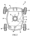
- Fig. 2 is a bottom plan view similar to Fig. 1 wherein the front wheels are arranged at an angle relative to the housing for the pool cleaner;
- Fig. 3 is an elevational view of a front wheel with a pin for holding the front wheel relative to the housing and a tie rod connecting member;
- Fig. 4 is a perspective view of a front wheel similar to Fig. 3;
- Fig. 5 is a cross-sectional view of front wheel with a reed switch connected thereto;
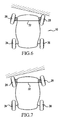
- Fig. 6 is a schematic view illustrating the front wheels being turned by the tie rod to a first angular relationship relative to the housing;
- Fig. 7 is a schematic view illustrating the front wheels being turned by the tie rod to a second angular relationship relative to the housing.
- a pool cleaner 10 for cleaning a swimming pool that includes a housing 12 with an upper surface 14 and downwardly projecting sidewalls extending downwardly from the upper surface 14 for defining a front end 16, a rear end 18, a first side 22 and a second side 24 of the housing 12.
- a first pair of wheels are mounted relative to the front end 16 of the housing, the first pair of wheels includes a first wheel 26 being pivotally mounted relative to the first side 22 of the housing 12 and a second wheel 28 that is pivotally mounted relative to the second side 24 of the housing 12.
- a tie rod 32 is operatively mounted relative to the first wheel 26 and the second wheel 28 for ensuring substantially the same angular relationship of the first wheel 26 and the second wheel 28 relative to the housing 12.
- a second pair of wheels 34, 36 are mounted relative to the rear end 18 of the housing 12. The second pair of wheels 34, 36 are connected to a drive mechanism 38 for providing rotary motion to the wheels 34, 36 for propelling the pool cleaner 10 relative to a surface of a swimming pool.
- the tie rod 32 imparts movement to the second wheel 28 for ensuring that the first wheel 26 and the second wheel 28 are at substantially the same angular relationship relative to the housing.
- the first wheel 26 and the second wheel 28 are arranged to be substantially in a longitudinal direction relative to the pool cleaner 10 for enabling the pool cleaner to move in substantially a straight path.
- the first wheel 26 and the second wheel 28 are arranged to be at an angular relationship relative to the housing 12 for enabling the pool cleaner to move in a trajectory that is at an angle relative to the previous trajectory of the pool cleaner 10.
- the pool cleaner 10 is designed to move completely randomly relative to a surface of a swimming pool to ensure that the entire swimming pool is cleaned.
- the first wheel 26 and the second wheel 28 projected outwardly relative to the front end 16 of the housing 12 for enabling either the first wheel 26 or the second wheel 28 to engage a wall surface of a pool for imparting a turning motion to the first wheel 26 or the second wheel 28 for changing the angular relationship of the wheels 26, 28 relative to the housing 12.
- the tie rod 32 is designed to move the first wheel 26 and the second wheel 28 in a controlled tandem relationship for maintaining the angular relationship of the wheels 26, 28 relative to the housing 12.
- a reversible drive mechanism 38 is provided for imparting rotation to the second pair of wheels 34, 36 for enabling the pool cleaner 10 to traverse a pool surface and for changing the trajectory of the pool cleaner when the first wheel 26 and second wheel 28 are moved to a predetermined angular relationship relative to the housing 12.
- Figs. 3-5 are enlarged views of the second wheel 28 and the mounting mechanism 40 for securing the second wheel 28 to the second side 24 of the housing 12.
- the mounting mechanism 40 includes a support 42 for securing the mounting mechanism 40 relative to the housing 12.
- a first arm 44 extends from the support 42.
- a second arm 48 is hinged at a proximal end to the first arm 44 by means of a pin 46.
- the tie rod 32 is connected to a distal end of the second arm 48 for ensuring that the first wheel 26 and the second wheel 28 are disposed at substantially the same angular relationship relative to the housing 12.
- the second wheel 28 is mounted relative to the mounting mechanism 40 at a point adjacent to the member 52.
- a second pivot connection 54 is provided on the first arm 44.
- the second wheel 28 is limited in the angle of swing.
- a larger angle of swing is desirable for an unusually shaped pool and/or a pool with obstructions to ensure complete coverage for the pool cleaner 10 for cleaning the swimming pool.
- the construction of the mounting mechanism for the first wheel is the same as the mounting mechanism 40 for the second wheel 28. Thus, a description of the mounting mechanism for the first wheel will not be provided.
- a motion sensor 62 is positioned within the second wheel 28 for detecting if the second wheel 28 engages a wall surface for actuating a control mechanism 64 for reversing the drive mechanism 38 for reversing the direction of the pool cleaner 10.
- the motion sensor 62 may be a reed switch with a magnet for directly measuring the wheel motion.
- a similar motion sensor is positioned within the first wheel 26 for actuating the control mechanism 64 for reversing the drive mechanism 38 for reversing the direction of the pool cleaner 10.
- Other types of motion sensors such as a proximity switch are within the scope of the present invention.
- a hollow axle is employed to permit a sensor wire to run through the axle without affecting wheel rotation and for providing an accurate and direct wheel rotation measurement.
- the control mechanism 64 includes a first random timing logic for delaying the reversing of the drive mechanism 38 after either the first wheel 26 or the second wheel 28 engages a wall surface of a pool.
- the control mechanism 64 includes a second random timing logic for periodic reversing of the drive mechanism randomly throughout a cleaning cycle of a pool.
- Figs. 6 and 7 illustrate schematic views of the pool cleaner 10 wherein the first wheel 26 and the second wheel 28 are tied together by the tie rod 32 to ensure that the first wheel 26 and the second wheel 28 are moved in the same direction.
- the tie rod 32 ensures that both the first wheel 26 and the second wheel 28 are moved in the same direction to be at substantially the same lateral angular relationship relative to the housing 12.
- the reverse path is more unpredictable. If the delay timing is long enough to allow the unit to keep pushing against the wall to the extent that the whole unit pivots about the point of the wheel and the wall contact, the whole unit rotates about the point of contact.
- the pool cleaner 10 will be at a random trajectory as compared to the previous trajectory. A longer push to rotate before the reversal of the drive mechanism results in a more dramatic turn between the forward path and the reverse path. A shorter push to rotate before the reversal of the drive mechanism results in a less dramatic turn between the forward path and the reverse path.
- the second random timing logic is provided in the control mechanism 64 for periodically reversing the direction of the cleaner while it is traversing a surface of the pool.
- the combination of the first random timing logic and the second random timing logic patterns assures unpredictability in the movement of the pool cleaner 10 for providing the best coverage of the pool surface.
Landscapes
- Engineering & Computer Science (AREA)
- Architecture (AREA)
- Civil Engineering (AREA)
- Structural Engineering (AREA)
- Electric Suction Cleaners (AREA)
- Vehicle Cleaning, Maintenance, Repair, Refitting, And Outriggers (AREA)
- Electric Vacuum Cleaner (AREA)
- Cleaning In General (AREA)
Applications Claiming Priority (1)
| Application Number | Priority Date | Filing Date | Title |
|---|---|---|---|
| US62687904P | 2004-11-12 | 2004-11-12 |
Publications (3)
| Publication Number | Publication Date |
|---|---|
| EP1659236A2 true EP1659236A2 (de) | 2006-05-24 |
| EP1659236A3 EP1659236A3 (de) | 2007-09-19 |
| EP1659236B1 EP1659236B1 (de) | 2011-06-29 |
Family
ID=35532416
Family Applications (1)
| Application Number | Title | Priority Date | Filing Date |
|---|---|---|---|
| EP05394031A Expired - Lifetime EP1659236B1 (de) | 2004-11-12 | 2005-11-14 | Radanordnung für einen Schwimmbeckenreinigungsmaschine |
Country Status (5)
| Country | Link |
|---|---|
| US (1) | US7797780B2 (de) |
| EP (1) | EP1659236B1 (de) |
| AT (1) | ATE514827T1 (de) |
| CA (1) | CA2526721C (de) |
| ES (1) | ES2372006T3 (de) |
Cited By (3)
| Publication number | Priority date | Publication date | Assignee | Title |
|---|---|---|---|---|
| WO2008102325A1 (en) * | 2007-02-23 | 2008-08-28 | Schneider, Anja Barbara | A swimming pool cleaner wheel axle |
| FR2927106A1 (fr) * | 2008-02-01 | 2009-08-07 | Claude Brenot | Robot de nettoyage automatique du fond d'un bassin. |
| CN103835537A (zh) * | 2012-11-20 | 2014-06-04 | 水产品股份有限公司 | 具有使车轴倾斜的机构的池清洗车 |
Families Citing this family (16)
| Publication number | Priority date | Publication date | Assignee | Title |
|---|---|---|---|---|
| CA2684846C (en) * | 2007-04-23 | 2015-01-27 | Zodiac Pool Care, Inc. | Swimming pool cleaner discs with pockets |
| US8343339B2 (en) | 2008-09-16 | 2013-01-01 | Hayward Industries, Inc. | Apparatus for facilitating maintenance of a pool cleaning device |
| USD598168S1 (en) | 2008-09-16 | 2009-08-11 | Hayward Industries, Inc. | Pool cleaner |
| USD630809S1 (en) | 2009-07-01 | 2011-01-11 | Hayward Industries, Inc. | Pool cleaner |
| USD630808S1 (en) | 2009-07-01 | 2011-01-11 | Hayward Industries, Inc. | Pool cleaner |
| FR2954380B1 (fr) * | 2009-12-18 | 2015-03-20 | Zodiac Pool Care Europe | Appareil nettoyeur de surface immergee a giration par cabrage |
| US8784652B2 (en) | 2010-09-24 | 2014-07-22 | Poolvergnuegen | Swimming pool cleaner with a rigid debris canister |
| US8869337B2 (en) | 2010-11-02 | 2014-10-28 | Hayward Industries, Inc. | Pool cleaning device with adjustable buoyant element |
| WO2014150506A1 (en) | 2013-03-15 | 2014-09-25 | Hayward Industries, Inc. | Pool cleaning device with wheel drive assemblies |
| FR3008442B1 (fr) * | 2013-07-11 | 2015-08-21 | Hexagone | Procede de nettoyage d'un bassin a l'aide d'un robot |
| USD789624S1 (en) | 2014-11-07 | 2017-06-13 | Hayward Industries, Inc. | Pool cleaner |
| USD789003S1 (en) | 2014-11-07 | 2017-06-06 | Hayward Industries, Inc. | Pool cleaner |
| USD787760S1 (en) | 2014-11-07 | 2017-05-23 | Hayward Industries, Inc. | Pool cleaner |
| USD787761S1 (en) | 2014-11-07 | 2017-05-23 | Hayward Industries, Inc. | Pool cleaner |
| USD1049524S1 (en) * | 2022-08-12 | 2024-10-29 | Shenzhen Aiper Intelligent Co., Ltd. | Swimming pool cleaner |
| CN115822335A (zh) * | 2022-10-31 | 2023-03-21 | 浙江明峰工贸股份有限公司 | 带有转向的泳池清洗车 |
Citations (1)
| Publication number | Priority date | Publication date | Assignee | Title |
|---|---|---|---|---|
| US20030159723A1 (en) | 2002-01-18 | 2003-08-28 | Hui Joseph Wing-Tak | Swimming pool cleaner |
Family Cites Families (16)
| Publication number | Priority date | Publication date | Assignee | Title |
|---|---|---|---|---|
| US659078A (en) * | 1900-05-23 | 1900-10-02 | Charles A Lieb | Motor-vehicle. |
| US1328681A (en) * | 1917-10-08 | 1920-01-20 | Macdonald Duncan | Automobile steering attachment |
| US1342507A (en) * | 1918-05-13 | 1920-06-08 | Maxwell Motor Company Inc | Towing connection for vehicles |
| US2146021A (en) * | 1936-05-29 | 1939-02-07 | Marx & Co Louis | Reversing toy vehicle |
| US2683956A (en) * | 1949-05-16 | 1954-07-20 | Robert J Conte | Toy automobile |
| US2988762A (en) * | 1960-02-08 | 1961-06-20 | Hugh H Babcock | Self-steering submarine suction cleaner |
| JPS5179497A (de) * | 1974-12-28 | 1976-07-10 | Sanko Co Inc | |
| JPS543376A (en) | 1977-06-09 | 1979-01-11 | Shin Meiwa Ind Co Ltd | Cleaner for water bottom of pool etc. |
| JPS549457A (en) | 1977-06-21 | 1979-01-24 | Shin Meiwa Ind Co Ltd | Bottom cleaner for pool or the like |
| JPS5450157A (en) | 1977-09-27 | 1979-04-19 | Shin Meiwa Ind Co Ltd | Apparatus for cleaning bottom of water in pool or the like |
| US4463520A (en) * | 1983-03-21 | 1984-08-07 | Buddy L Corporation | Self-returning toy vehicle |
| EP0356577B1 (de) * | 1988-08-20 | 1991-03-27 | Pooltec Establishment | Saugkopf zum Reinigen untergetauchter Flächen |
| US5454129A (en) * | 1994-09-01 | 1995-10-03 | Kell; Richard T. | Self-powered pool vacuum with remote controlled capabilities |
| US5956626A (en) * | 1996-06-03 | 1999-09-21 | Motorola, Inc. | Wireless communication device having an electromagnetic wave proximity sensor |
| US5974347A (en) * | 1997-03-14 | 1999-10-26 | Nelson; Russell G. | Automated lawn mower |
| US6412133B1 (en) * | 1999-01-25 | 2002-07-02 | Aqua Products, Inc. | Water jet reversing propulsion and directional controls for automated swimming pool cleaners |
-
2005
- 2005-11-09 US US11/269,826 patent/US7797780B2/en not_active Expired - Fee Related
- 2005-11-10 CA CA2526721A patent/CA2526721C/en not_active Expired - Fee Related
- 2005-11-14 ES ES05394031T patent/ES2372006T3/es not_active Expired - Lifetime
- 2005-11-14 EP EP05394031A patent/EP1659236B1/de not_active Expired - Lifetime
- 2005-11-14 AT AT05394031T patent/ATE514827T1/de not_active IP Right Cessation
Patent Citations (1)
| Publication number | Priority date | Publication date | Assignee | Title |
|---|---|---|---|---|
| US20030159723A1 (en) | 2002-01-18 | 2003-08-28 | Hui Joseph Wing-Tak | Swimming pool cleaner |
Cited By (4)
| Publication number | Priority date | Publication date | Assignee | Title |
|---|---|---|---|---|
| WO2008102325A1 (en) * | 2007-02-23 | 2008-08-28 | Schneider, Anja Barbara | A swimming pool cleaner wheel axle |
| FR2927106A1 (fr) * | 2008-02-01 | 2009-08-07 | Claude Brenot | Robot de nettoyage automatique du fond d'un bassin. |
| WO2009095626A3 (fr) * | 2008-02-01 | 2009-09-24 | Claude Brenot | Robot de nettoyage automatique du fond d'un bassin |
| CN103835537A (zh) * | 2012-11-20 | 2014-06-04 | 水产品股份有限公司 | 具有使车轴倾斜的机构的池清洗车 |
Also Published As
| Publication number | Publication date |
|---|---|
| EP1659236A3 (de) | 2007-09-19 |
| ES2372006T3 (es) | 2012-01-12 |
| EP1659236B1 (de) | 2011-06-29 |
| US7797780B2 (en) | 2010-09-21 |
| CA2526721A1 (en) | 2006-05-12 |
| ATE514827T1 (de) | 2011-07-15 |
| US20060101596A1 (en) | 2006-05-18 |
| CA2526721C (en) | 2011-09-20 |
Similar Documents
| Publication | Publication Date | Title |
|---|---|---|
| EP1659236B1 (de) | Radanordnung für einen Schwimmbeckenreinigungsmaschine | |
| CN100586356C (zh) | 机器人清洁设备 | |
| US4471567A (en) | Two-way operating ball enclosed vehicle | |
| US8560119B2 (en) | Robot cleaner and method of controlling travel of the same | |
| US9162154B2 (en) | Autonomous vehicle system | |
| BR112012006769B1 (pt) | veículo, em particular, um robô de brinquedo que se coloca de pé com motor vibratório | |
| KR20110054839A (ko) | 로봇청소기의 제어방법 | |
| TWI752596B (zh) | 清掃機器人 | |
| US3751851A (en) | Toy vehicle | |
| JP7283804B2 (ja) | 掃除機 | |
| JP2005211499A (ja) | 自走式掃除機 | |
| CN107296569A (zh) | 自主行走型清扫机 | |
| JP2016002453A (ja) | 自走式清掃装置の走行方法 | |
| TWM449621U (zh) | 玩具車輛 | |
| JP2003236776A (ja) | 移動ロボット | |
| JP2001092546A (ja) | 自走式ロボットの操縦装置 | |
| CN105641939B (zh) | 手动行进玩具 | |
| JPH0584173A (ja) | 電気掃除機 | |
| KR100779193B1 (ko) | 로봇청소기 및 로봇청소기 제어방법 | |
| JP2003169769A (ja) | 自走式清掃装置 | |
| KR102483396B1 (ko) | 진공 청소기 | |
| JP2008030549A (ja) | 無人搬送車の従動輪旋回制限機構 | |
| JPH05204450A (ja) | 電気掃除機 | |
| JP2000237979A (ja) | 歩行用ロボット | |
| JP4544594B2 (ja) | パチンコ遊技機の球払出装置 |
Legal Events
| Date | Code | Title | Description |
|---|---|---|---|
| PUAI | Public reference made under article 153(3) epc to a published international application that has entered the european phase |
Free format text: ORIGINAL CODE: 0009012 |
|
| AK | Designated contracting states |
Kind code of ref document: A2 Designated state(s): AT BE BG CH CY CZ DE DK EE ES FI FR GB GR HU IE IS IT LI LT LU LV MC NL PL PT RO SE SI SK TR |
|
| AX | Request for extension of the european patent |
Extension state: AL BA HR MK YU |
|
| RIN1 | Information on inventor provided before grant (corrected) |
Inventor name: HUI, JOSEPH Inventor name: HOLSTEIN RICHARD |
|
| RIN1 | Information on inventor provided before grant (corrected) |
Inventor name: HOLSTEIN RICHARD Inventor name: HUI, JOSEPH |
|
| RIN1 | Information on inventor provided before grant (corrected) |
Inventor name: HOLSTEIN RICHARD Inventor name: HUI, JOSEPH |
|
| PUAL | Search report despatched |
Free format text: ORIGINAL CODE: 0009013 |
|
| AK | Designated contracting states |
Kind code of ref document: A3 Designated state(s): AT BE BG CH CY CZ DE DK EE ES FI FR GB GR HU IE IS IT LI LT LU LV MC NL PL PT RO SE SI SK TR |
|
| AX | Request for extension of the european patent |
Extension state: AL BA HR MK YU |
|
| 17P | Request for examination filed |
Effective date: 20080114 |
|
| 17Q | First examination report despatched |
Effective date: 20080227 |
|
| AKX | Designation fees paid |
Designated state(s): AT BE BG CH CY CZ DE DK EE ES FI FR GB GR HU IE IS IT LI LT LU LV MC NL PL PT RO SE SI SK TR |
|
| GRAP | Despatch of communication of intention to grant a patent |
Free format text: ORIGINAL CODE: EPIDOSNIGR1 |
|
| GRAS | Grant fee paid |
Free format text: ORIGINAL CODE: EPIDOSNIGR3 |
|
| GRAA | (expected) grant |
Free format text: ORIGINAL CODE: 0009210 |
|
| AK | Designated contracting states |
Kind code of ref document: B1 Designated state(s): AT BE BG CH CY CZ DE DK EE ES FI FR GB GR HU IE IS IT LI LT LU LV MC NL PL PT RO SE SI SK TR |
|
| REG | Reference to a national code |
Ref country code: GB Ref legal event code: FG4D |
|
| REG | Reference to a national code |
Ref country code: CH Ref legal event code: EP |
|
| REG | Reference to a national code |
Ref country code: IE Ref legal event code: FG4D |
|
| REG | Reference to a national code |
Ref country code: DE Ref legal event code: R096 Ref document number: 602005028728 Country of ref document: DE Effective date: 20110825 |
|
| REG | Reference to a national code |
Ref country code: NL Ref legal event code: VDEP Effective date: 20110629 |
|
| PG25 | Lapsed in a contracting state [announced via postgrant information from national office to epo] |
Ref country code: LT Free format text: LAPSE BECAUSE OF FAILURE TO SUBMIT A TRANSLATION OF THE DESCRIPTION OR TO PAY THE FEE WITHIN THE PRESCRIBED TIME-LIMIT Effective date: 20110629 Ref country code: SE Free format text: LAPSE BECAUSE OF FAILURE TO SUBMIT A TRANSLATION OF THE DESCRIPTION OR TO PAY THE FEE WITHIN THE PRESCRIBED TIME-LIMIT Effective date: 20110629 |
|
| PG25 | Lapsed in a contracting state [announced via postgrant information from national office to epo] |
Ref country code: AT Free format text: LAPSE BECAUSE OF FAILURE TO SUBMIT A TRANSLATION OF THE DESCRIPTION OR TO PAY THE FEE WITHIN THE PRESCRIBED TIME-LIMIT Effective date: 20110629 Ref country code: GR Free format text: LAPSE BECAUSE OF FAILURE TO SUBMIT A TRANSLATION OF THE DESCRIPTION OR TO PAY THE FEE WITHIN THE PRESCRIBED TIME-LIMIT Effective date: 20110930 Ref country code: SI Free format text: LAPSE BECAUSE OF FAILURE TO SUBMIT A TRANSLATION OF THE DESCRIPTION OR TO PAY THE FEE WITHIN THE PRESCRIBED TIME-LIMIT Effective date: 20110629 Ref country code: LV Free format text: LAPSE BECAUSE OF FAILURE TO SUBMIT A TRANSLATION OF THE DESCRIPTION OR TO PAY THE FEE WITHIN THE PRESCRIBED TIME-LIMIT Effective date: 20110629 Ref country code: FI Free format text: LAPSE BECAUSE OF FAILURE TO SUBMIT A TRANSLATION OF THE DESCRIPTION OR TO PAY THE FEE WITHIN THE PRESCRIBED TIME-LIMIT Effective date: 20110629 |
|
| PG25 | Lapsed in a contracting state [announced via postgrant information from national office to epo] |
Ref country code: BE Free format text: LAPSE BECAUSE OF FAILURE TO SUBMIT A TRANSLATION OF THE DESCRIPTION OR TO PAY THE FEE WITHIN THE PRESCRIBED TIME-LIMIT Effective date: 20110629 |
|
| REG | Reference to a national code |
Ref country code: ES Ref legal event code: FG2A Ref document number: 2372006 Country of ref document: ES Kind code of ref document: T3 Effective date: 20120112 |
|
| PG25 | Lapsed in a contracting state [announced via postgrant information from national office to epo] |
Ref country code: EE Free format text: LAPSE BECAUSE OF FAILURE TO SUBMIT A TRANSLATION OF THE DESCRIPTION OR TO PAY THE FEE WITHIN THE PRESCRIBED TIME-LIMIT Effective date: 20110629 Ref country code: CZ Free format text: LAPSE BECAUSE OF FAILURE TO SUBMIT A TRANSLATION OF THE DESCRIPTION OR TO PAY THE FEE WITHIN THE PRESCRIBED TIME-LIMIT Effective date: 20110629 Ref country code: NL Free format text: LAPSE BECAUSE OF FAILURE TO SUBMIT A TRANSLATION OF THE DESCRIPTION OR TO PAY THE FEE WITHIN THE PRESCRIBED TIME-LIMIT Effective date: 20110629 Ref country code: PT Free format text: LAPSE BECAUSE OF FAILURE TO SUBMIT A TRANSLATION OF THE DESCRIPTION OR TO PAY THE FEE WITHIN THE PRESCRIBED TIME-LIMIT Effective date: 20111031 Ref country code: IS Free format text: LAPSE BECAUSE OF FAILURE TO SUBMIT A TRANSLATION OF THE DESCRIPTION OR TO PAY THE FEE WITHIN THE PRESCRIBED TIME-LIMIT Effective date: 20111029 |
|
| PG25 | Lapsed in a contracting state [announced via postgrant information from national office to epo] |
Ref country code: CY Free format text: LAPSE BECAUSE OF FAILURE TO SUBMIT A TRANSLATION OF THE DESCRIPTION OR TO PAY THE FEE WITHIN THE PRESCRIBED TIME-LIMIT Effective date: 20110629 Ref country code: RO Free format text: LAPSE BECAUSE OF FAILURE TO SUBMIT A TRANSLATION OF THE DESCRIPTION OR TO PAY THE FEE WITHIN THE PRESCRIBED TIME-LIMIT Effective date: 20110629 Ref country code: SK Free format text: LAPSE BECAUSE OF FAILURE TO SUBMIT A TRANSLATION OF THE DESCRIPTION OR TO PAY THE FEE WITHIN THE PRESCRIBED TIME-LIMIT Effective date: 20110629 Ref country code: PL Free format text: LAPSE BECAUSE OF FAILURE TO SUBMIT A TRANSLATION OF THE DESCRIPTION OR TO PAY THE FEE WITHIN THE PRESCRIBED TIME-LIMIT Effective date: 20110629 |
|
| PLBE | No opposition filed within time limit |
Free format text: ORIGINAL CODE: 0009261 |
|
| STAA | Information on the status of an ep patent application or granted ep patent |
Free format text: STATUS: NO OPPOSITION FILED WITHIN TIME LIMIT |
|
| 26N | No opposition filed |
Effective date: 20120330 |
|
| PG25 | Lapsed in a contracting state [announced via postgrant information from national office to epo] |
Ref country code: DK Free format text: LAPSE BECAUSE OF FAILURE TO SUBMIT A TRANSLATION OF THE DESCRIPTION OR TO PAY THE FEE WITHIN THE PRESCRIBED TIME-LIMIT Effective date: 20110629 Ref country code: MC Free format text: LAPSE BECAUSE OF NON-PAYMENT OF DUE FEES Effective date: 20111130 |
|
| REG | Reference to a national code |
Ref country code: CH Ref legal event code: PL |
|
| GBPC | Gb: european patent ceased through non-payment of renewal fee |
Effective date: 20111114 |
|
| PG25 | Lapsed in a contracting state [announced via postgrant information from national office to epo] |
Ref country code: LI Free format text: LAPSE BECAUSE OF NON-PAYMENT OF DUE FEES Effective date: 20111130 Ref country code: CH Free format text: LAPSE BECAUSE OF NON-PAYMENT OF DUE FEES Effective date: 20111130 |
|
| REG | Reference to a national code |
Ref country code: DE Ref legal event code: R097 Ref document number: 602005028728 Country of ref document: DE Effective date: 20120330 |
|
| REG | Reference to a national code |
Ref country code: IE Ref legal event code: MM4A |
|
| PG25 | Lapsed in a contracting state [announced via postgrant information from national office to epo] |
Ref country code: IE Free format text: LAPSE BECAUSE OF NON-PAYMENT OF DUE FEES Effective date: 20111114 Ref country code: GB Free format text: LAPSE BECAUSE OF NON-PAYMENT OF DUE FEES Effective date: 20111114 |
|
| PG25 | Lapsed in a contracting state [announced via postgrant information from national office to epo] |
Ref country code: LU Free format text: LAPSE BECAUSE OF NON-PAYMENT OF DUE FEES Effective date: 20111114 |
|
| PG25 | Lapsed in a contracting state [announced via postgrant information from national office to epo] |
Ref country code: BG Free format text: LAPSE BECAUSE OF FAILURE TO SUBMIT A TRANSLATION OF THE DESCRIPTION OR TO PAY THE FEE WITHIN THE PRESCRIBED TIME-LIMIT Effective date: 20110929 |
|
| PG25 | Lapsed in a contracting state [announced via postgrant information from national office to epo] |
Ref country code: TR Free format text: LAPSE BECAUSE OF FAILURE TO SUBMIT A TRANSLATION OF THE DESCRIPTION OR TO PAY THE FEE WITHIN THE PRESCRIBED TIME-LIMIT Effective date: 20110629 |
|
| PG25 | Lapsed in a contracting state [announced via postgrant information from national office to epo] |
Ref country code: HU Free format text: LAPSE BECAUSE OF FAILURE TO SUBMIT A TRANSLATION OF THE DESCRIPTION OR TO PAY THE FEE WITHIN THE PRESCRIBED TIME-LIMIT Effective date: 20110629 |
|
| PGFP | Annual fee paid to national office [announced via postgrant information from national office to epo] |
Ref country code: IT Payment date: 20131113 Year of fee payment: 9 |
|
| PGFP | Annual fee paid to national office [announced via postgrant information from national office to epo] |
Ref country code: ES Payment date: 20141013 Year of fee payment: 10 |
|
| REG | Reference to a national code |
Ref country code: FR Ref legal event code: PLFP Year of fee payment: 11 |
|
| PG25 | Lapsed in a contracting state [announced via postgrant information from national office to epo] |
Ref country code: IT Free format text: LAPSE BECAUSE OF NON-PAYMENT OF DUE FEES Effective date: 20141114 |
|
| REG | Reference to a national code |
Ref country code: FR Ref legal event code: PLFP Year of fee payment: 12 |
|
| REG | Reference to a national code |
Ref country code: ES Ref legal event code: FD2A Effective date: 20161227 |
|
| PG25 | Lapsed in a contracting state [announced via postgrant information from national office to epo] |
Ref country code: ES Free format text: LAPSE BECAUSE OF NON-PAYMENT OF DUE FEES Effective date: 20151115 |
|
| REG | Reference to a national code |
Ref country code: FR Ref legal event code: PLFP Year of fee payment: 13 |
|
| PGFP | Annual fee paid to national office [announced via postgrant information from national office to epo] |
Ref country code: DE Payment date: 20171108 Year of fee payment: 13 Ref country code: FR Payment date: 20171012 Year of fee payment: 13 |
|
| REG | Reference to a national code |
Ref country code: DE Ref legal event code: R119 Ref document number: 602005028728 Country of ref document: DE |
|
| PG25 | Lapsed in a contracting state [announced via postgrant information from national office to epo] |
Ref country code: DE Free format text: LAPSE BECAUSE OF NON-PAYMENT OF DUE FEES Effective date: 20190601 Ref country code: FR Free format text: LAPSE BECAUSE OF NON-PAYMENT OF DUE FEES Effective date: 20181130 |