EP1656894A1 - Devices for selectively macerating and sculpting tissue - Google Patents
Devices for selectively macerating and sculpting tissue Download PDFInfo
- Publication number
- EP1656894A1 EP1656894A1 EP05256936A EP05256936A EP1656894A1 EP 1656894 A1 EP1656894 A1 EP 1656894A1 EP 05256936 A EP05256936 A EP 05256936A EP 05256936 A EP05256936 A EP 05256936A EP 1656894 A1 EP1656894 A1 EP 1656894A1
- Authority
- EP
- European Patent Office
- Prior art keywords
- nozzle
- fluid jet
- evacuation
- tube
- instrument
- Prior art date
- Legal status (The legal status is an assumption and is not a legal conclusion. Google has not performed a legal analysis and makes no representation as to the accuracy of the status listed.)
- Withdrawn
Links
- 230000002879 macerating effect Effects 0.000 title description 2
- 239000012530 fluid Substances 0.000 claims abstract description 167
- 210000001519 tissue Anatomy 0.000 description 66
- 238000000034 method Methods 0.000 description 5
- 238000002803 maceration Methods 0.000 description 3
- 241000791420 Plica Species 0.000 description 2
- 230000000694 effects Effects 0.000 description 2
- 239000007788 liquid Substances 0.000 description 2
- 238000002679 ablation Methods 0.000 description 1
- 210000000577 adipose tissue Anatomy 0.000 description 1
- 210000003484 anatomy Anatomy 0.000 description 1
- 210000000988 bone and bone Anatomy 0.000 description 1
- 230000003628 erosive effect Effects 0.000 description 1
- 239000000463 material Substances 0.000 description 1
- 230000003349 osteoarthritic effect Effects 0.000 description 1
- 239000002245 particle Substances 0.000 description 1
- 230000000717 retained effect Effects 0.000 description 1
- 238000007493 shaping process Methods 0.000 description 1
- 210000004872 soft tissue Anatomy 0.000 description 1
- 239000002699 waste material Substances 0.000 description 1
Images


Classifications
-
- A—HUMAN NECESSITIES
- A61—MEDICAL OR VETERINARY SCIENCE; HYGIENE
- A61B—DIAGNOSIS; SURGERY; IDENTIFICATION
- A61B17/00—Surgical instruments, devices or methods
- A61B17/32—Surgical cutting instruments
- A61B17/3203—Fluid jet cutting instruments
-
- A—HUMAN NECESSITIES
- A61—MEDICAL OR VETERINARY SCIENCE; HYGIENE
- A61B—DIAGNOSIS; SURGERY; IDENTIFICATION
- A61B17/00—Surgical instruments, devices or methods
- A61B17/16—Instruments for performing osteoclasis; Drills or chisels for bones; Trepans
- A61B17/1644—Instruments for performing osteoclasis; Drills or chisels for bones; Trepans using fluid other than turbine drive fluid
-
- A—HUMAN NECESSITIES
- A61—MEDICAL OR VETERINARY SCIENCE; HYGIENE
- A61B—DIAGNOSIS; SURGERY; IDENTIFICATION
- A61B17/00—Surgical instruments, devices or methods
- A61B17/32—Surgical cutting instruments
- A61B17/3203—Fluid jet cutting instruments
- A61B17/32037—Fluid jet cutting instruments for removing obstructions from inner organs or blood vessels, e.g. for atherectomy
-
- A—HUMAN NECESSITIES
- A61—MEDICAL OR VETERINARY SCIENCE; HYGIENE
- A61B—DIAGNOSIS; SURGERY; IDENTIFICATION
- A61B17/00—Surgical instruments, devices or methods
- A61B17/16—Instruments for performing osteoclasis; Drills or chisels for bones; Trepans
- A61B17/1644—Instruments for performing osteoclasis; Drills or chisels for bones; Trepans using fluid other than turbine drive fluid
- A61B2017/1648—Instruments for performing osteoclasis; Drills or chisels for bones; Trepans using fluid other than turbine drive fluid as cutting jet
-
- A—HUMAN NECESSITIES
- A61—MEDICAL OR VETERINARY SCIENCE; HYGIENE
- A61B—DIAGNOSIS; SURGERY; IDENTIFICATION
- A61B2217/00—General characteristics of surgical instruments
- A61B2217/002—Auxiliary appliance
- A61B2217/005—Auxiliary appliance with suction drainage system
Definitions
- This application relates to high pressure fluid jets for macerating and sculpting tissue.
- Fluid jet cutters focus pressurized fluid to impact desired tissue and thereby emulsify the tissue. The tissue can then be suctioned or otherwise removed from the surgical site.
- Many devices utilize a closed-loop system that includes a collection tube positioned a distance apart from the fluid jet nozzle for collecting both the fluid jet and the removed tissue.
- the instrument includes a fluid delivery tube having a nozzle formed thereon, preferably at a distal end thereof, for forming a high pressure fluid jet, and an evacuation tube having an evacuation port or fluid-jet receiving port formed thereon, preferably at a distal end thereof, for collecting the high pressure fluid jet from the nozzle on the delivery tube.
- a fluid delivery tube having a nozzle formed thereon, preferably at a distal end thereof, for forming a high pressure fluid jet
- an evacuation tube having an evacuation port or fluid-jet receiving port formed thereon, preferably at a distal end thereof, for collecting the high pressure fluid jet from the nozzle on the delivery tube.
- at least one of the nozzle and the evacuation port can be movable relative to one another to allow the instrument to be selectively used for both bulk removal, whereby the tissue is macerated, and for precision sculpting, whereby the tissue is cut.
- the evacuation tube can be movable to move the evacuation port from a first position, in which the nozzle is substantially axially aligned with the evacuation port, to a second position, in which the nozzle is offset from a central axis of the evacuation port.
- the fluid jet delivered from the nozzle can be used for bulk removal to macerate tissue, as the positioning of the nozzle relative to the evacuation tube requires a shear cutting plane of the fluid jet to extend transversely into the tissue surface being macerated.
- the instrument is preferably used to macerate soft tissue, such as plica and fat.
- the fluid jet delivered from the nozzle can be used for precision sculpting to cut fine tissue particles because the positioning of the nozzle relative to the evacuation tube allows the shear cutting plane of the fluid jet to be positioned substantially tangential to the tissue surface.
- the second position is useful, for example, to sculpt hard tissue, such as bone.
- the present invention also provides methods for selective bulk removal and precision sculpting of tissue.
- an exemplary instrument for selective bulk removal and precision sculpting of tissue
- an exemplary instrument includes a fluid delivery tube having a nozzle for forming a high pressure fluid jet, and an evacuation tube having an evacuation port or jet-receiving opening opposite to and spaced apart from the nozzle for receiving the high pressure fluid jet.
- the evacuation port and/or the nozzle can be moved relative to one another to allow the device to be selectively used for bulk removal of tissue to macerate the tissue and for precision sculpting of tissue to cut the tissue.
- the fluid delivery tube and the evacuation tube can have a variety of other configurations, and they can be incorporated into and/or include features present in various other fluid jet cutting instruments known in the art.
- bulk removal and variations thereof is intended to encompass the mass ablation of large quantities of redundant tissue such as, but not limited to fat, fat pad, plica, osteoarthritic tissue, and the term “precision sculpting” and variations thereof is intended to encompass the removal or shaping of functional anatomy which has been damaged or diseased in order to approximate the original shape and functionality.
- macroerate and variations thereof is intended to encompass crushing between the fluid jet and a portion of the collection tube such that the tissue is ablated (almost formed into a liquefied material)
- cut and variations thereof is intended to encompass removing tissue from the body using the fluid jet such that the tissue is pushed by the jet or entrained within the jet and collected in the collection tube.
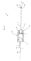
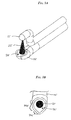
- FIG. 1A illustrates one exemplary embodiment of a surgical fluid jet cutting instrument.
- the instrument 10 generally includes a fluid delivery tube 12 and an evacuation tube 14.
- Each tube 12, 14 has a substantially elongated shape with an inner lumen extending therethrough between proximal and distal ends 12a, 12b, 14a, 14b thereof.
- the tubes 12, 14 can be directly mated to one another, or a portion of each tube 12, 14 can be disposed within an outer housing 16 for retaining the tubes 12, 14 relative to one another, as shown.
- the outer housing 16 can have virtually any shape and size, and it can optionally be in the form of a handle to facilitate grasping of the device.
- the outer housing 16 functions to allow movement of the fluid delivery tube 12 relative to the evacuation tube 14, as will be discussed in more detail below.
- the outer housing 16, and in particular the fluid delivery tube 12 is also designed to couple to a high pressure liquid source, such as a high pressure pump or liquid dispenser, for delivering fluid to the fluid delivery tube 12.
- the outer housing 16, and more particularly the evacuation tube 14, can also optionally be configured to couple to a source of suction, such as a vacuum pump, aspirator, or to a waste canister for collecting fluid and tissue evacuated through the evacuation tube 14.
- a source of suction such as a vacuum pump, aspirator
- the proximal end 12a, 14a of the fluid delivery tube 12 and the evacuation tube 14 can extend into a handle or another housing that is connected to a fluid delivery source and a suction device.
- each tube 12, 14, which is shown in more detail in FIGS. 1B-1G, can also have a variety of configurations.
- the distal end 12b of the fluid delivery tube 12 can be curved away from the evacuation tube 14 such that the fluid delivery tube 12 and the evacuation tube 14 are spaced a distance apart from one another.
- the fluid delivery tube 12 preferably includes a nozzle 18 formed thereon and opposed to the evacuation tube 14 for forming and delivering a high pressure fluid jet 22.
- the nozzle 18 is in communication with the inner lumen (not shown) such that when the proximal end 12a of the fluid delivery tube 12 is coupled to a high pressure fluid source, fluid can be delivered through the fluid delivery tube 12 to the nozzle 18, which forms a fluid jet 22 having a specific shape and size.
- the evacuation tube 14 can include an evacuation port 20 for receiving the fluid jet 22, and any tissue contained therein.
- the evacuation port 20 can extend into the inner lumen extending through the evacuation tube 14 to allow the fluid jet 22 and the tissue to be collected.
- the nozzle 18 is preferably positioned a distance apart from and opposite to the evacuation port 20.
- the distance d will depend on the size of the fluid jet, but preferably the distance d is configured such that the diameter of the fluid jet 22 as it enters the evacuation port 20 occupies a predetermined area of the evacuation port. While this predetermined area can vary depending on the intended use, in an exemplary embodiment the fluid jet 22 occupies approximately 50% to 60% of the evacuation port 20. The fluid jet 22 can occupy less than 50% of the evacuation port 20, however such a configuration may result in a fluid jet that is effective to sculpt the tissue without being effective to macerate the tissue.
- the fluid jet 22 can occupy more than 60% and up to 100% of the evacuation port 20, however such a configuration may result in a fluid jet that is effective to macerate tissue without being effective to sculpt the tissue.
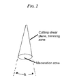
- the distanced d will vary depending on the size of the fluid jet 22 as well as the desired area of the evacuation port 20 to be occupied by the fluid jet 22, in an exemplary embodiment the distance d between the nozzle 18 and the evacuation port 20 is configured such that the fluid jet 22 has a cone angle A , shown in FIG. 2, that is in the range of about 15° to 20°, and more preferably that is about 17° to 19°.
- the distance d can be in the range of about 1 mm to 5 mm.
- the size of the fluid jet 22 relative to the size of the evacuation port 20 allows the fluid jet 22 to be collected at various locations within the evacuation port 20, thus allowing the instrument 10 to be used to selectively macerate and sculpt tissue.
- the pressure of the fluid jet 22 can also vary, but in an exemplary embodiment the fluid jet 22 is delivered at a pressure that is in the range of about 1000 PSI to 20,000 PSI, more preferably 5000 PSI to 15,000 PSI.
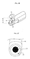
- the evacuation port 20 formed in the evacuation tube 12 can have a variety of shapes and sizes. In the embodiment shown in FIGS. 1A-1G, the evacuation port 20 is substantially circular in shape.
- the fluid jet 22 can be adjusted both radially and axially with respect to the evacuation port 20.
- FIG. 1B illustrates the nozzle 18 on the fluid delivery tube 12 aligned with a mid-portion of the evacuation port 20 such that the fluid jet 22 is collected at the mid-portion of the evacuation port 20, as shown in FIG. 1C. In this position, the fluid jet 22 is particularly suitable for use in bulk removal of tissue, as will be discussed in more detail below. The fluid jet 22 can then be adjusted for use in precision sculpting, as will also be discussed in more detail below.
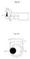
- the fluid delivery tube 12 or the evacuation tube 14 can be axially translated from the position shown in FIG. 1B to the position shown in FIG. 1D. In this position, the fluid jet 22 is delivered to the tip of the evacuation port 20, as shown in FIG. 1E.
- the fluid delivery tube 12 or the evacuation tube 14 can be radially translated from the position shown in FIG. 1B to the position shown in FIG. 1E wherein the fluid jet 22 is delivered to a side of the evacuation port 20, as shown in FIG. 1F.
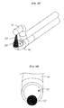
- the evacuation port 20' can be substantially pear-shaped or tear-shaped.
- the evacuation port 20' includes a central substantially circular region 20a' and an offset pointed region 20b'.
- the evacuation tube also preferably has a pear-shape or tear-shape to contour the shape of the evacuation port 20'. In use, the shape allows the fluid jet 22' to be received at various locations in the evacuation port 20'.
- FIG. 3A illustrates the fluid delivery tube 12' aligned with a mid-portion of the evacuation port 20' such that the fluid jet 22' is collected at the mid-portion of the evacuation port 20', as shown in FIG. 3B.
- the fluid jet 22' is particularly suitable for use in bulk removal of tissue, as will be discussed in more detail below.
- the fluid jet 22' can then be adjusted for use in precision sculpting, as will also be discussed in more detail below.
- the fluid delivery tube 12' or the evacuation tube 14' can be axially translated from the position shown in FIG. 3A to the position shown in FIG. 3C.
- the fluid jet 22' is delivered to the tip or pointed region 20b' of the evacuation port 20', as shown in FIG. 3D.
- the fluid jet 22' can also be moved radially to deliver the fluid jet 22' to a side of the evacuation port 20'.
- the instrument 10 can include a handle 28 that is coupled to the housing 16 and that receives a portion of the evacuation tube 14 and the fluid delivery tube 12.
- a cam mechanism is disposed within the handle 28 and it is effective to axially move the fluid delivery tube 12 with respect to the evacuation tube 14.
- the cam mechanism includes a radial switch 25 that is rotatably disposed within the handle 28 and that includes a cam ramp 31 formed on a distal end thereof.
- the cam ramp 31 is coupled to a cam follower 29, which is rigidly attached to the housing 16 and the fluid delivery tube 12, and which is preloaded onto the switch 25 via a spring 27 that is retained inside the handle 28.
- the cam ramp 31 forces the cam follower 29 to move axially, thereby axially moving the housing 16 and the fluid delivery tube 12 to adjust the position of the fluid jet 22 with respect to the evacuation port 20 in the evacuation tube 14.
- the radial switch 25 is also preferably coupled to an evacuation housing 24 that is disposed within the handle 28. This ensures that the housing 16 and the fluid delivery tube 12 move a distance axially that is dictated by the cam ramp 21 on the switch 25.
- a person skilled in the art will appreciate that a variety of techniques can be used to effect axial movement of the fluid delivery tube 12 and/or the evacuation tube 14 relative to one another. Moreover, techniques known in the art can also be used to cause the fluid delivery tube 12 and/or the evacuation tube 14 to pivot, rotate, or otherwise move about the longitudinal axis L thereof.
- fluid 22 jet is shown in more detail, and as shown the fluid jet 22 includes a shear cutting plane which is formed around a perimeter thereof along a length thereof, and a maceration zone, which is internal to the cutting plane.
- the fluid jet 22 can be used for bulk removal of tissue such that the tissue within the maceration zone will be macerated.
- the fluid jet 22, 22' can be used for precision sculpting of tissue. Precision sculpting of the tissue can be achieved when the fluid jet 22 is positioned to be collected adjacent to a perimeter of the evacuation port 20, as shown in FIGS. 1D-1G and 3C-3D, such that the fluid delivery tube 12 and the evacuation tube 14 do not interfere with the tangential contact between the fluid jet 22 and the tissue surface 30. Accordingly, by providing a movable fluid delivery tube 12 and/or movable evacuation tube 14, the fluid jet 22 can be selectively positioned for use in bulk removal of tissue and for use in precision sculpting of tissue.
- the fluid jet 22 is first positioned as shown in FIGS. 1B-1C and 3A-3B such that the fluid jet 22 is collected at a substantial mid-portion of the evacuation port.
- the instrument is then positioned adjacent to a tissue surface such that the high pressure fluid jet 22 extends transversely into the tissue surface for bulk removal of the tissue.
- the macerated tissue can be collected with the fluid jet 22 in the evacuation port 20 and through the evacuation tube 14.
- the fluid jet 22 is moved to a second position as shown in FIGS. 1D-1G and 3C-3D such that the fluid jet 22 is collected adjacent to a perimeter of the evacuation port 20.
- the instrument is then positioned adjacent to a tissue surface 30, as is also shown in FIG. 4, such that the high pressure fluid jet 22 is tangential to the tissue surface 30 for precision sculpting of the tissue.
- the fluid jet 22 and the removed tissue can be collected in the evacuation tube 14.
Landscapes
- Health & Medical Sciences (AREA)
- Surgery (AREA)
- Life Sciences & Earth Sciences (AREA)
- Medical Informatics (AREA)
- Animal Behavior & Ethology (AREA)
- Engineering & Computer Science (AREA)
- Biomedical Technology (AREA)
- Heart & Thoracic Surgery (AREA)
- Veterinary Medicine (AREA)
- Molecular Biology (AREA)
- Nuclear Medicine, Radiotherapy & Molecular Imaging (AREA)
- General Health & Medical Sciences (AREA)
- Public Health (AREA)
- Vascular Medicine (AREA)
- Dentistry (AREA)
- Oral & Maxillofacial Surgery (AREA)
- Orthopedic Medicine & Surgery (AREA)
- Surgical Instruments (AREA)
- Perforating, Stamping-Out Or Severing By Means Other Than Cutting (AREA)
Applications Claiming Priority (1)
| Application Number | Priority Date | Filing Date | Title |
|---|---|---|---|
| US10/904,456 US20060100569A1 (en) | 2004-11-11 | 2004-11-11 | Methods and devices for selective bulk removal and precision sculpting of tissue |
Publications (1)
| Publication Number | Publication Date |
|---|---|
| EP1656894A1 true EP1656894A1 (en) | 2006-05-17 |
Family
ID=35709089
Family Applications (1)
| Application Number | Title | Priority Date | Filing Date |
|---|---|---|---|
| EP05256936A Withdrawn EP1656894A1 (en) | 2004-11-11 | 2005-11-10 | Devices for selectively macerating and sculpting tissue |
Country Status (5)
| Country | Link |
|---|---|
| US (1) | US20060100569A1 (enExample) |
| EP (1) | EP1656894A1 (enExample) |
| JP (1) | JP2006136727A (enExample) |
| AU (1) | AU2005229679B2 (enExample) |
| CA (1) | CA2526514A1 (enExample) |
Families Citing this family (19)
| Publication number | Priority date | Publication date | Assignee | Title |
|---|---|---|---|---|
| US7794408B2 (en) * | 2003-03-28 | 2010-09-14 | Ethicon, Inc. | Tissue collection device and methods |
| US8034003B2 (en) | 2003-09-11 | 2011-10-11 | Depuy Mitek, Inc. | Tissue extraction and collection device |
| US7611473B2 (en) * | 2003-09-11 | 2009-11-03 | Ethicon, Inc. | Tissue extraction and maceration device |
| US20060120899A1 (en) | 2004-12-07 | 2006-06-08 | Depuy Mitek, Inc. | Reusable pump cartridge |
| US20060142773A1 (en) | 2004-12-29 | 2006-06-29 | Depuy Mitek, Inc. | Abrasive cutting system and method |
| WO2008083278A2 (en) * | 2006-12-29 | 2008-07-10 | Dion Ernest A | Wound bed preparation |
| US8642664B2 (en) | 2007-08-06 | 2014-02-04 | Samir Mitragotri | Composition for solubilizing tissue and cells comprising N-tetradecyl-N,N-dimethyl-3-ammonio-1-propanesulfonate and polyoxyethylene (10) cetyl ether |
| US8389582B2 (en) | 2007-08-06 | 2013-03-05 | Samir Mitragotri | Composition for solubilizing tissue comprising 3-(decyl dimethyl ammonio) propane sulfonate and tetraethylene glycol dodecyl ether |
| US9909098B2 (en) * | 2007-08-06 | 2018-03-06 | The Regents Of The University Of California | Methods of tissue-based diagnosis |
| US8609041B2 (en) | 2007-08-06 | 2013-12-17 | Samir Mitragotri | Apparatus for solubilizing tissue |
| US9814422B2 (en) | 2007-08-06 | 2017-11-14 | The Regents Of The University Of California | Compositions for solubilizing cells and/or tissue |
| EP2055481B1 (en) * | 2007-10-18 | 2017-08-16 | Bobst Italia S.P.A. | Doctor blade assembly and a method for allowing different inks to be used |
| CN104655828B (zh) * | 2009-02-13 | 2018-04-27 | 加州大学评议会 | 基于组织的诊断的系统、方法和装置 |
| US8337175B2 (en) | 2009-12-22 | 2012-12-25 | Smith & Nephew, Inc. | Disposable pumping system and coupler |
| JP5862020B2 (ja) * | 2011-02-28 | 2016-02-16 | セイコーエプソン株式会社 | 流体噴射装置 |
| WO2017136051A1 (en) * | 2015-12-18 | 2017-08-10 | Boston Scientific Scimed, Inc. | Tissue manipulation tool |
| US11116537B2 (en) | 2017-06-13 | 2021-09-14 | Board Of Regents Of The University Of Nebraska | Surgical devices and methods |
| WO2019074700A1 (en) * | 2017-10-09 | 2019-04-18 | The Board Of Regents Of The University Of Oklahoma | SURGICAL EVACUATION APPARATUS AND ASSOCIATED METHOD |
| CN113795205B (zh) * | 2019-03-07 | 2024-10-11 | 普罗赛普特生物机器人公司 | 从手术部位的材料移除 |
Citations (3)
| Publication number | Priority date | Publication date | Assignee | Title |
|---|---|---|---|---|
| US4690672A (en) * | 1984-09-06 | 1987-09-01 | Veltrup Elmar M | Apparatus for removing solid structures from body passages |
| US6375635B1 (en) * | 1999-05-18 | 2002-04-23 | Hydrocision, Inc. | Fluid jet surgical instruments |
| EP1433423A1 (en) * | 2002-11-15 | 2004-06-30 | Ethicon, Inc. | Tissue biopsy and processing device |
Family Cites Families (7)
| Publication number | Priority date | Publication date | Assignee | Title |
|---|---|---|---|---|
| CA2048120A1 (en) * | 1990-08-06 | 1992-02-07 | William J. Drasler | Thrombectomy method and device |
| US6135977A (en) * | 1994-02-16 | 2000-10-24 | Possis Medical, Inc. | Rheolytic catheter |
| US5527330A (en) * | 1994-08-18 | 1996-06-18 | United States Surgical Corporation | Fluid cutting instrument |
| US5871462A (en) * | 1995-06-07 | 1999-02-16 | Hydrocision, Inc. | Method for using a fluid jet cutting system |
| US5944686A (en) * | 1995-06-07 | 1999-08-31 | Hydrocision, Inc. | Instrument for creating a fluid jet |
| US6511493B1 (en) * | 2000-01-10 | 2003-01-28 | Hydrocision, Inc. | Liquid jet-powered surgical instruments |
| US20060129086A1 (en) * | 2004-12-13 | 2006-06-15 | Depuy Mitek, Inc. | Interchangeable tissue macerating and sculpting methods and devices |
-
2004
- 2004-11-11 US US10/904,456 patent/US20060100569A1/en not_active Abandoned
-
2005
- 2005-11-02 AU AU2005229679A patent/AU2005229679B2/en not_active Ceased
- 2005-11-10 CA CA002526514A patent/CA2526514A1/en not_active Abandoned
- 2005-11-10 JP JP2005326441A patent/JP2006136727A/ja not_active Abandoned
- 2005-11-10 EP EP05256936A patent/EP1656894A1/en not_active Withdrawn
Patent Citations (3)
| Publication number | Priority date | Publication date | Assignee | Title |
|---|---|---|---|---|
| US4690672A (en) * | 1984-09-06 | 1987-09-01 | Veltrup Elmar M | Apparatus for removing solid structures from body passages |
| US6375635B1 (en) * | 1999-05-18 | 2002-04-23 | Hydrocision, Inc. | Fluid jet surgical instruments |
| EP1433423A1 (en) * | 2002-11-15 | 2004-06-30 | Ethicon, Inc. | Tissue biopsy and processing device |
Also Published As
| Publication number | Publication date |
|---|---|
| AU2005229679A1 (en) | 2006-05-25 |
| US20060100569A1 (en) | 2006-05-11 |
| AU2005229679B2 (en) | 2007-12-06 |
| JP2006136727A (ja) | 2006-06-01 |
| CA2526514A1 (en) | 2006-05-11 |
Similar Documents
| Publication | Publication Date | Title |
|---|---|---|
| EP1656894A1 (en) | Devices for selectively macerating and sculpting tissue | |
| JP2006503682A5 (enExample) | ||
| JP2006503682A (ja) | 液体噴流支援型の組織操作を組み込んだ手術装置及びその使用法 | |
| CN105816220B (zh) | 外科工具的刚性护套 | |
| EP1322240B1 (en) | Endoscopic shaver | |
| US20060229550A1 (en) | Liquid jet surgical instrument | |
| EP2412320B1 (en) | Labrum retracting burr | |
| US8162966B2 (en) | Surgical devices incorporating liquid jet assisted tissue manipulation and methods for their use | |
| CN101394877B (zh) | 远端形状选择性可控的液体喷射外科器械 | |
| US5728129A (en) | Distal atherectomy catheter | |
| EP1065983B1 (en) | Device for implanting small-diameter capillary grafts | |
| KR20140109924A (ko) | 표적 조직의 신속한 제거를 위한 안전한 커팅 헤드 및 시스템 | |
| US20080281224A1 (en) | Biopsy device needle tip | |
| JP2002543913A (ja) | 流体ジェット外科機器 | |
| WO1998019609A1 (en) | Surgical tubular cutter having a tapering cutting chamber | |
| JP2007516048A (ja) | 開口方向性及び改良チップを備えた生検装置 | |
| CN103281973A (zh) | 组织去除装置 | |
| CA2529014C (en) | Interchangeable tissue macerating and sculpting methods and devices | |
| KR102221770B1 (ko) | 미세침습수술용 절제조직 제거장치 | |
| JPH01232945A (ja) | 外科用手術装置 | |
| CN116997300A (zh) | 手术切割工具 | |
| KR101750757B1 (ko) | 환부 세절장치 | |
| CN120304917B (zh) | 乳腺肿瘤手术器械 | |
| KR102871018B1 (ko) | 조직제거용 의료기기 | |
| US20250248729A1 (en) | Endovascular devices with extendible shaver |
Legal Events
| Date | Code | Title | Description |
|---|---|---|---|
| PUAI | Public reference made under article 153(3) epc to a published international application that has entered the european phase |
Free format text: ORIGINAL CODE: 0009012 |
|
| AK | Designated contracting states |
Kind code of ref document: A1 Designated state(s): AT BE BG CH CY CZ DE DK EE ES FI FR GB GR HU IE IS IT LI LT LU LV MC NL PL PT RO SE SI SK TR |
|
| AX | Request for extension of the european patent |
Extension state: AL BA HR MK YU |
|
| 17P | Request for examination filed |
Effective date: 20061102 |
|
| 17Q | First examination report despatched |
Effective date: 20061201 |
|
| AKX | Designation fees paid |
Designated state(s): DE FR GB IT |
|
| STAA | Information on the status of an ep patent application or granted ep patent |
Free format text: STATUS: THE APPLICATION IS DEEMED TO BE WITHDRAWN |
|
| 18D | Application deemed to be withdrawn |
Effective date: 20100601 |