EP2055481B1 - Doctor blade assembly and a method for allowing different inks to be used - Google Patents
Doctor blade assembly and a method for allowing different inks to be used Download PDFInfo
- Publication number
- EP2055481B1 EP2055481B1 EP07020393.0A EP07020393A EP2055481B1 EP 2055481 B1 EP2055481 B1 EP 2055481B1 EP 07020393 A EP07020393 A EP 07020393A EP 2055481 B1 EP2055481 B1 EP 2055481B1
- Authority
- EP
- European Patent Office
- Prior art keywords
- doctor blade
- support structure
- printing
- unit
- holding device
- Prior art date
- Legal status (The legal status is an assumption and is not a legal conclusion. Google has not performed a legal analysis and makes no representation as to the accuracy of the status listed.)
- Active
Links
- 239000000976 ink Substances 0.000 title claims description 49
- 238000000034 method Methods 0.000 title claims description 5
- 238000007639 printing Methods 0.000 claims description 89
- 238000007646 gravure printing Methods 0.000 claims description 21
- 230000008878 coupling Effects 0.000 claims description 5
- 238000010168 coupling process Methods 0.000 claims description 5
- 238000005859 coupling reaction Methods 0.000 claims description 5
- 239000000463 material Substances 0.000 description 12
- 238000004140 cleaning Methods 0.000 description 4
- 239000000126 substance Substances 0.000 description 4
- 239000012530 fluid Substances 0.000 description 3
- 238000007599 discharging Methods 0.000 description 2
- 238000001035 drying Methods 0.000 description 2
- 230000004075 alteration Effects 0.000 description 1
- 230000000712 assembly Effects 0.000 description 1
- 238000000429 assembly Methods 0.000 description 1
- 230000008859 change Effects 0.000 description 1
- 230000002860 competitive effect Effects 0.000 description 1
- 230000000694 effects Effects 0.000 description 1
- 230000003993 interaction Effects 0.000 description 1
- 238000012423 maintenance Methods 0.000 description 1
- 238000012544 monitoring process Methods 0.000 description 1
- 239000005022 packaging material Substances 0.000 description 1
- 230000000737 periodic effect Effects 0.000 description 1
- 230000008569 process Effects 0.000 description 1
- 238000011144 upstream manufacturing Methods 0.000 description 1
Images


Classifications
-
- B—PERFORMING OPERATIONS; TRANSPORTING
- B41—PRINTING; LINING MACHINES; TYPEWRITERS; STAMPS
- B41F—PRINTING MACHINES OR PRESSES
- B41F9/00—Rotary intaglio printing presses
- B41F9/06—Details
- B41F9/08—Wiping mechanisms
- B41F9/10—Doctors, scrapers, or like devices
- B41F9/1036—Clamping and adjusting devices
-
- B—PERFORMING OPERATIONS; TRANSPORTING
- B41—PRINTING; LINING MACHINES; TYPEWRITERS; STAMPS
- B41F—PRINTING MACHINES OR PRESSES
- B41F31/00—Inking arrangements or devices
- B41F31/02—Ducts, containers, supply or metering devices
- B41F31/04—Ducts, containers, supply or metering devices with duct-blades or like metering devices
- B41F31/05—Positioning devices therefor
Definitions
- the present invention relates to a doctor blade assembly for use with rotating print cylinders, in particular print cylinders of gravure or rotogravure printing presses, and further relates to a method for allowing different inks to be used.
- Doctor blades are known in the field of printing apparatuses, in particular rotogravure printing presses in which a gravure printing roller applies ink onto a film or web material to be printed, such as a packaging material.
- the doctor blade is arranged adjacent and substantially parallel to the rotation axis of the printing roller, which is typically engraved according to the graphics or patterns to be printed onto the material.
- a pan containing the ink or other substances to be applied to the material is usually provided beneath the printing roller, in such a position that the printing roller can be wet by the ink or the substance in the pan during its rotation.
- the material to be printed is generally fed to the printing roller by a pressing roller, which is in close proximity of the printing roller so that the material can contact a generating line of the printing roller downstream of the ink pan and can be printed according to the patterns engraved on the printing roller.
- the doctor blade is placed downstream of the ink pan and upstream of the pressing roller, with respect to the rotation direction of the printing roller, and is aimed at wiping off the excess ink from the engraved surface of the printing roller before it contacts the material to be printed, so that the ink remains only in the patterned recesses engraved on the surface of the printing roller.
- one print cycle may need inks for high quality applications and another print cycle may need inks for lower quality applications or adapted for different materials to be printed.
- two different printing presses at the same plant would be very expensive and would double operation and maintenance activities.
- the document US-6,095,045 A describes a doctor blade device for filling depressions in a cylinder of a printing machine with a fluid, comprising:
- Aim of the instant invention is to solve the above problems, by providing an assembly which allows different inks or other substances for film or web materials to be used within the same printing press.
- an object of the invention is to allow the printing press to be easily switched from one printing mode to another printing mode.
- Another object is to allow the assembly to be installed and used in existing rotary printing presses, in particular gravure or rotogravure printing presses, without substantially changing their mechanical structure and their operating software.
- Yet another object of the invention is to reduce cleaning operations of rotary printing presses.
- Not least object is to provide an assembly which is further competitive from a merely economical standpoint.
- a doctor blade assembly for printing units in particular for rotogravure printing units, comprising a support structure for a doctor blade, a holding device of the support structure and a moving means of the holding device, characterized in that the holding device comprises mounting means which are suitable to indifferently fix either a chambered doctor blade or a non-chambered doctor blade to the moving means.
- the support structure is substantially L-shaped, at least one arm of the L-shaped support structure being detachably fixed to the holding device by means of the mounting means.
- the mounting means may comprise any one of: at least one screw, a clamp, a snap-fit coupling, a geometrical coupling.
- the support structure comprises at least one handle or a pair of handles.
- a rotogravure printing unit comprising at least one gravure printing roller and at least one pressing roller adjacent to said gravure printing roller, characterized in that the rotogravure printing unit comprises the above doctor blade assembly.
- a chambered doctor blade can be removably fixed to the moving means by virtue of the mounting means, the moving means being suitable to adjust the position of the chambered doctor blade with respect to the lateral surface of said gravure printing roller.
- a rotogravure printing unit 100 incorporating the doctor blade assembly comprises at least one gravure printing roller 4A and a pressing roller 4B, both of the conventional kind, which are rotatably mounted on a support frame 7 of the unit 100.
- the gravure printing roller 4A features an engraved cylindrical surface, by means of which ink can be entrapped and transferred to a film or web material fed by the pressing roller 4B.
- the gravure printing roller 4A can be easily disassembled from the unit 100 and replaced by a gravure printing roller having a different diameter and/or different patterns engraved on its surface.
- the pressing roller 4B is linearly movable with respect to the rotation axis of the gravure printing roller 4A, so as to be adapted to printing rollers of different diameters and to press the film or web material against the engraved surface of the printing roller 4A.
- a first motor 13a and a second motor 13b are located on the top of the support frame 7 and are able to actuate, via a first motor shaft 15a and a second motor shaft 15b, the pressure roller 4B towards the printing roller 4A.
- the rotogravure printing unit 100 further comprises a doctor blade assembly 101.
- the doctor blade assembly comprises a support structure for a doctor blade such as a chambered doctor blade 1, which support is removably fixed to a holding device 2 substantially at a middle height of the rotogravure printing unit 100.
- the holding device 2 comprises a support rod 3 for connection to a moving means 5 such as a pneumatic, hydraulic or electromechanical actuation device, which is suitable to adjust the position of the holding device and, accordingly, of the doctor blade fixed thereto, with respect to the surface of a printing roller.
- the moving means 5 can move the holding device 2 and the rod 3 so as to adapt the radial position of the chambered doctor blade 1 to the diameter of the particular printing roller used, and/or to change the angular position of the chambered doctor blade 1 with respect to the gravure printing roller, and/or to bring the chambered doctor blade 1 to an operational position, i.e. abutting against the gravure printing roller 4A, or to a non-operational position, i.e. away from the gravure printing roller 4A.
- Actuation devices for moving doctor blades with respect to the printing rollers are well known in the field of rotogravure printing presses for moving non-chambered doctor blades, and will not be discussed in detail here.
- the holding device 2 as it will become better apparent from the description of the doctor blade assemblies of figure 3-5 , comprises mounting means which are suitable to indifferently fix either a chambered doctor blade 1, like that depicted in figures 1A-1B , or a non-chambered doctor blade to the moving means 5.
- a conventional ink pan can be provided beneath the gravure printing roller 4A, so as to make the roller surface be dipped, during its rotation, in the ink contained in the pan.
- the ink pan should be used in the rotogravure printing unit 100 when the doctor blade fastened to the holding device 2 is a non-chambered doctor blade, such as that shown in figure 3 .
- An ink tank 6 is also provided, preferably outside of the support frame 7, for supplying ink to the rotogravure printing unit when the doctor blade fastened to the holding device 2 is a chambered doctor blade 1, as shown in figures 1A-1B , 2 , 4 and 5 .
- a hose 8 is connected between the ink tank 6 and a supply inlet 9 of the chambered doctor blade 1.
- the supply inlet is located in a bottom region of the chambered doctor blade 1.
- a discharge hose 10 is further connected to a corresponding outlet of the chambered doctor blade 1 and in the proximity of the supply inlet 9, for discharging of the ink from the chambered doctor blade 1.
- a viscometer 11 located above the ink tank 6 may be provided for monitoring viscosity of the ink.
- Figure 2 shows a detailed view of a chambered doctor blade 1.
- the chambered doctor blade 1 extends along the length of the printing roller 4A and preferably exceeds such length.
- the chambered doctor blade 1 comprises a support structure 17 which is substantially L-shaped and a box mounted thereon for defining an ink chamber which is closed by the lateral surface of the printing roller 4A.
- the chamber is defined by a first lower doctor 20, a second upper doctor 24 and lateral contoured walls 22.
- the first doctor 20 is fastened to the support structure 17 by means of a clamp block 18.
- the second doctor 24 is located above the first doctor 20 and is fixed to the support structure 17 by means of a second clamp block 34.
- a discharge channel 21 for discharging excess ink is preferably located in the support structure 17 below the curved area of the second doctor blade 20. Moreover, a manifold is provided inside the chamber, for allowing ink be sprayed towards the printing roller 4A.
- a J-shaped bar 27 is located above the second clamp block 34 and articulated to a pivot 30.
- An adjustment element 28 is provided on the flat arm of the J-shaped bar 27, for changing the slope of the second doctor 24.
- a first plate 25 is fixed to the end surface of the curved side of the J-shaped bar 27 and contacts the second doctor 24. As a consequence, by turning the adjustment element 28, the J-shaped bar 27 can rotate clockwise or counter clockwise around pivot 30, changing the angle of the second doctor 24 with respect to the surface of the printing roller 4A.
- the holding device 2 comprises a substantially rectangular support block 41 which comprises mounting means adapted for the support structure of both the chambered doctor blade shown in figure 2 and the non-chambered doctor blade shown in figure 3 .
- the mounting means comprise a threaded hole 40 on the side facing the bottom surface of an arm 37 of the L-shaped support structure 17, which hole is suitable for a corresponding screw 38 of the L-shaped support structure 17 of the chambered doctor blade and for a corresponding screw 69 of the L-shaped support structure 51 of the non-chambered doctor blade (see figure 3 ).
- Articulated to a pivot 42 is a support lever 43 of the actuation device 5, which is suitable to adjust the position of the chambered doctor blade with respect to the printing roller 4A.
- the actuation device preferably, is computer controlled for achieving a high precision positioning.
- the chambered doctor blade of figure 2 may comprise handles fixed to the support structure 17, such as the handle 50 depicted in figure 5 , which allow easy assembling or disassembling of the chambered doctor blade and its support structure with respect to the holding device 41.
- Figure 3 shows a non-chambered doctor blade assembly mounted on the same holding device 41 and its corresponding support lever 43 of figure 2 .
- the non-chambered doctor blade has a support structure 51 which defines, together with an elongated arm 68, a substantially L-shaped support structure.
- Attached to the support structure 51 are trapezoid side plates 52 and an upper doctor 54, which is held in place by a plate 57 and a fixing element 62.
- the non-chambered doctor blade of figure 3 may also comprise handles fixed to the support structure 51, suitable to easily assemble or disassemble the non-chambered doctor blade and its support structure with respect to the holding device 41.
- Figure 4 shows a further case, in which the mounting means of the holding device of the chambered doctor blade of figure 2 have been slightly changed with respect to the corresponding mounting means of figures 2 and 3 .
- the holding device is a holding block 71 comprising, on its upper surface, a mounting means in the form of a protruding clamp 72 and its corresponding clamping screw 73 and, below the free end of the claim 72, a threaded hole 78 for the clamping screw 73.
- the holding block 71 as the holding device of figures 2-3 , is pivoted at 74 to a support lever 75 of moving means for adjusting the position of the chambered doctor blade with respect to the printing roller 4A.
- the moving means preferably, are computer controlled for achieving a high precision positioning.
- the clamp 72 is located on the holding block 71 so that the free arm of the clamp is directed substantially towards the same direction of the front edge of the holding block 71, in order to clamp and fix the L-shaped support structure of the doctor blade to the holding block 71.
- the holding device may be provided with one or more of the mounting means listed above, as well as with their equivalents, so as to be adapted to support different doctor blade units.
- Figure 5 shows a chambered doctor blade.
- the chambered doctor blade differs from the chambered doctor blade of figure 2 in that it further comprises a handle 50 which is fixed to the upper surface of the L-shaped support structure 17.
- a handle 50 which is fixed to the upper surface of the L-shaped support structure 17.
- two handles 50 are provided on the L-shaped support structure 17, so that a user can easily grip the chambered doctor blade unit and remove it from the holding device, as well as fit it onto the holding device.
- a non-chambered doctor blade such as that shown in figure 3
- the moving means 5 are actuated so as to adjust and maintain the position of the non-chambered doctor blade with respect to the lateral surface of the gravure printing roller 4A.
- the ink pan beneath the gravure printing roller 4A is filled with ink, so that the gravure printing roller 4A can be wet with the ink during its rotation and the excess ink can be removed from the engraved surface of the roller 4A by means of the doctor of the non-chambered doctor blade unit before printing the film or web material supplied by the pressing roller.
- the moving means 5 are actuated so as to move the non-chambered doctor blade unit away from the printing roller, in the non-operational position, and the user can easily disassemble the non-chambered doctor blade and its support structure from the holding device, e.g. by removing the screw 69 and lifting the non-chambered doctor blade unit by means of the handles fixed to its support structure.
- the ink pan is emptied from the ink used in the previous printing cycle or can be moved away from the printing roller 4A.
- the chambered doctor blade such as that shown in figure 5 , is brought and fitted onto the holding device 2 by means of the handles 50 and is finally fixed to the holding device, e.g. by means of the screw 38 in the same threaded hole 40 of the holding block 41.
- the moving means are actuated so as to bring the holding device and the chambered doctor blade unit in the operational position, i.e. at the periphery of the gravure printing roller 4A. Accordingly, the ink is supplied to the printing roller 4A at an angular position which is closer to the pressing roller than the position of the ink pan, allowing to use inks that could not be otherwise used in a rotogravure printing unit.
- doctor blade assembly which allows different inks or substances to be used within the same printing unit, because of the provision of mounting means which allow different kinds of doctor blade units to be installed thereon.
- doctor blade interchangeability which characterizes the doctor blade assembly according to the invention allows a printing unit to be easily switched from one printing mode to another printing mode.
- An important consequence is that the cleaning operations of printing presses such as rotogravure printing presses are drastically reduced, because such printing presses can also operate with chambered doctor blade units, without causing ink splashes and other well known drawbacks due to the interaction between the printing roller and the ink pan or vessel beneath the roller.
- doctor blade assembly does not need any substantial alteration of the mechanical structure and of the operating software of existing printing unit, which can be easily updated with such assembly.
Landscapes
- Engineering & Computer Science (AREA)
- Mechanical Engineering (AREA)
- Inking, Control Or Cleaning Of Printing Machines (AREA)
- Rotary Presses (AREA)
Description
- The present invention relates to a doctor blade assembly for use with rotating print cylinders, in particular print cylinders of gravure or rotogravure printing presses, and further relates to a method for allowing different inks to be used.
- Doctor blades are known in the field of printing apparatuses, in particular rotogravure printing presses in which a gravure printing roller applies ink onto a film or web material to be printed, such as a packaging material.
- In a rotogravure printing press, the doctor blade is arranged adjacent and substantially parallel to the rotation axis of the printing roller, which is typically engraved according to the graphics or patterns to be printed onto the material. A pan containing the ink or other substances to be applied to the material is usually provided beneath the printing roller, in such a position that the printing roller can be wet by the ink or the substance in the pan during its rotation.
- The material to be printed is generally fed to the printing roller by a pressing roller, which is in close proximity of the printing roller so that the material can contact a generating line of the printing roller downstream of the ink pan and can be printed according to the patterns engraved on the printing roller.
- The doctor blade is placed downstream of the ink pan and upstream of the pressing roller, with respect to the rotation direction of the printing roller, and is aimed at wiping off the excess ink from the engraved surface of the printing roller before it contacts the material to be printed, so that the ink remains only in the patterned recesses engraved on the surface of the printing roller.
- During the above printing process, a common problem is usually encountered, which is that unused ink can accumulate beneath the doctor blade and some ink can splash on the material to be printed and on the inner walls of the chamber enclosing the printing roller. As a consequence, without a periodic cleaning of the printing group, quality of print cycles degrades in time. Therefore, cleaning of the doctor blade unit, which is in close proximity of the printing color ink is an extremely important requirement to maintain excellent print quality.
- Another known problem is that not any kind of ink can be used with rotogravure printing presses. For instance, some inks may be too fast drying or have too low viscosity, which makes them unsuitable to gravure printing presses because of the large extension of the rotation arc between the ink pan beneath the printing roller and the pressing roller, the latter being above the printing roller.
- On the other hand, within a same printing plant, one print cycle may need inks for high quality applications and another print cycle may need inks for lower quality applications or adapted for different materials to be printed. This would require two independent print presses, e.g. a rotogravure printing press using a non-chambered doctor blade and a flexographic printing press using a chambered doctor blade and a lot of space would be accordingly needed. Moreover, providing two different printing presses at the same plant would be very expensive and would double operation and maintenance activities.
- The document
US-6,095,045 A describes a doctor blade device for filling depressions in a cylinder of a printing machine with a fluid, comprising: - ink application means;
- a fluid conveyance system connected to the application means;
- a working blade arranged after the application means in a rotational direction of the cylinder, the application means including a chamber doctor which connects with a removal space defined by the working blade, the chamber doctor being movable away from the cylinder independently of the working blade; and
- a carrier removably mounted on a support, the chamber doctor being mounted on the carrier, the working blade being mounted to the support, the chamber doctor being removable from the cylinder so as to allow fluid to flow out of the application means, the working blade being in contact with the cylinder when the chamber doctor is removed.
- Aim of the instant invention is to solve the above problems, by providing an assembly which allows different inks or other substances for film or web materials to be used within the same printing press.
- Within the above aim, an object of the invention is to allow the printing press to be easily switched from one printing mode to another printing mode.
- Another object is to allow the assembly to be installed and used in existing rotary printing presses, in particular gravure or rotogravure printing presses, without substantially changing their mechanical structure and their operating software.
- Yet another object of the invention is to reduce cleaning operations of rotary printing presses.
- Not least object is to provide an assembly which is further competitive from a merely economical standpoint.
- This aim, these objects and other objects which will become better apparent hereinafter are achieved by a doctor blade assembly for printing units, in particular for rotogravure printing units, comprising a support structure for a doctor blade, a holding device of the support structure and a moving means of the holding device, characterized in that the holding device comprises mounting means which are suitable to indifferently fix either a chambered doctor blade or a non-chambered doctor blade to the moving means.
- Advantageously, the support structure is substantially L-shaped, at least one arm of the L-shaped support structure being detachably fixed to the holding device by means of the mounting means. The mounting means may comprise any one of: at least one screw, a clamp, a snap-fit coupling, a geometrical coupling.
- Preferably, the support structure comprises at least one handle or a pair of handles.
- The above aim and objects are also achieved by a rotogravure printing unit comprising at least one gravure printing roller and at least one pressing roller adjacent to said gravure printing roller, characterized in that the rotogravure printing unit comprises the above doctor blade assembly.
- In such a rotogravure printing unit, a chambered doctor blade can be removably fixed to the moving means by virtue of the mounting means, the moving means being suitable to adjust the position of the chambered doctor blade with respect to the lateral surface of said gravure printing roller.
- Further characteristics and advantages of the present invention will become better apparent from the following description of particular embodiments thereof, illustrated only by way of non-limitative examples in the accompanying drawings.
-
-
Figure 1A shows a rotogravure printing unit comprising a chambered doctor blade in non-operational mode; -
Figure 1B shows a left-side view of the rotogravure printing unit ofFig. 1A in an operational mode; -
Figure 2 shows a first chambered doctor blade assembly in cross-section; -
Figure 3 shows a non-chambered doctor blade assembly in cross-section; -
Figure 4 shows a second chambered doctor blade assembly; -
Figure 5 shows a third chambered doctor blade assembly. - With reference to
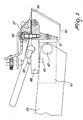
Figures 1A and1B , arotogravure printing unit 100 incorporating the doctor blade assembly comprises at least onegravure printing roller 4A and apressing roller 4B, both of the conventional kind, which are rotatably mounted on asupport frame 7 of theunit 100. - The
gravure printing roller 4A features an engraved cylindrical surface, by means of which ink can be entrapped and transferred to a film or web material fed by thepressing roller 4B. Thegravure printing roller 4A can be easily disassembled from theunit 100 and replaced by a gravure printing roller having a different diameter and/or different patterns engraved on its surface. - The
pressing roller 4B is linearly movable with respect to the rotation axis of thegravure printing roller 4A, so as to be adapted to printing rollers of different diameters and to press the film or web material against the engraved surface of theprinting roller 4A. - Preferably, a
first motor 13a and asecond motor 13b are located on the top of thesupport frame 7 and are able to actuate, via afirst motor shaft 15a and asecond motor shaft 15b, thepressure roller 4B towards theprinting roller 4A. - The
rotogravure printing unit 100 further comprises adoctor blade assembly 101. The doctor blade assembly comprises a support structure for a doctor blade such as achambered doctor blade 1, which support is removably fixed to aholding device 2 substantially at a middle height of therotogravure printing unit 100. - In particular, the
holding device 2 comprises a support rod 3 for connection to a movingmeans 5 such as a pneumatic, hydraulic or electromechanical actuation device, which is suitable to adjust the position of the holding device and, accordingly, of the doctor blade fixed thereto, with respect to the surface of a printing roller. For instance, the movingmeans 5 can move theholding device 2 and the rod 3 so as to adapt the radial position of thechambered doctor blade 1 to the diameter of the particular printing roller used, and/or to change the angular position of thechambered doctor blade 1 with respect to the gravure printing roller, and/or to bring thechambered doctor blade 1 to an operational position, i.e. abutting against thegravure printing roller 4A, or to a non-operational position, i.e. away from thegravure printing roller 4A. - Actuation devices for moving doctor blades with respect to the printing rollers, as well as their control software, are well known in the field of rotogravure printing presses for moving non-chambered doctor blades, and will not be discussed in detail here.
- The
holding device 2, as it will become better apparent from the description of the doctor blade assemblies offigure 3-5 , comprises mounting means which are suitable to indifferently fix either achambered doctor blade 1, like that depicted infigures 1A-1B , or a non-chambered doctor blade to the movingmeans 5. - A conventional ink pan can be provided beneath the
gravure printing roller 4A, so as to make the roller surface be dipped, during its rotation, in the ink contained in the pan. The ink pan should be used in therotogravure printing unit 100 when the doctor blade fastened to theholding device 2 is a non-chambered doctor blade, such as that shown infigure 3 . - An
ink tank 6 is also provided, preferably outside of thesupport frame 7, for supplying ink to the rotogravure printing unit when the doctor blade fastened to theholding device 2 is achambered doctor blade 1, as shown infigures 1A-1B ,2 ,4 and5 . - In particular, a hose 8 is connected between the
ink tank 6 and asupply inlet 9 of thechambered doctor blade 1. In a preferred case, the supply inlet is located in a bottom region of thechambered doctor blade 1. - A
discharge hose 10 is further connected to a corresponding outlet of thechambered doctor blade 1 and in the proximity of thesupply inlet 9, for discharging of the ink from thechambered doctor blade 1. - Optionally, a
viscometer 11 located above theink tank 6 may be provided for monitoring viscosity of the ink. -
Figure 2 shows a detailed view of achambered doctor blade 1. Thechambered doctor blade 1 extends along the length of theprinting roller 4A and preferably exceeds such length. - The
chambered doctor blade 1 comprises asupport structure 17 which is substantially L-shaped and a box mounted thereon for defining an ink chamber which is closed by the lateral surface of theprinting roller 4A. - In particular, the chamber is defined by a first
lower doctor 20, a secondupper doctor 24 and lateralcontoured walls 22. Thefirst doctor 20 is fastened to thesupport structure 17 by means of aclamp block 18. Thesecond doctor 24 is located above thefirst doctor 20 and is fixed to thesupport structure 17 by means of asecond clamp block 34. - A
discharge channel 21 for discharging excess ink is preferably located in thesupport structure 17 below the curved area of thesecond doctor blade 20. Moreover, a manifold is provided inside the chamber, for allowing ink be sprayed towards theprinting roller 4A. - A J-shaped
bar 27 is located above thesecond clamp block 34 and articulated to apivot 30. Anadjustment element 28 is provided on the flat arm of the J-shapedbar 27, for changing the slope of thesecond doctor 24. Afirst plate 25 is fixed to the end surface of the curved side of the J-shapedbar 27 and contacts thesecond doctor 24. As a consequence, by turning theadjustment element 28, the J-shapedbar 27 can rotate clockwise or counter clockwise aroundpivot 30, changing the angle of thesecond doctor 24 with respect to the surface of theprinting roller 4A. - The holding
device 2 comprises a substantiallyrectangular support block 41 which comprises mounting means adapted for the support structure of both the chambered doctor blade shown infigure 2 and the non-chambered doctor blade shown infigure 3 . - In the particular case depicted in
figure 2 , the mounting means comprise a threadedhole 40 on the side facing the bottom surface of anarm 37 of the L-shapedsupport structure 17, which hole is suitable for acorresponding screw 38 of the L-shapedsupport structure 17 of the chambered doctor blade and for acorresponding screw 69 of the L-shapedsupport structure 51 of the non-chambered doctor blade (seefigure 3 ). - Articulated to a
pivot 42 is asupport lever 43 of theactuation device 5, which is suitable to adjust the position of the chambered doctor blade with respect to theprinting roller 4A. The actuation device, preferably, is computer controlled for achieving a high precision positioning. - The chambered doctor blade of
figure 2 may comprise handles fixed to thesupport structure 17, such as thehandle 50 depicted infigure 5 , which allow easy assembling or disassembling of the chambered doctor blade and its support structure with respect to the holdingdevice 41. -
Figure 3 shows a non-chambered doctor blade assembly mounted on thesame holding device 41 and itscorresponding support lever 43 offigure 2 . The non-chambered doctor blade has asupport structure 51 which defines, together with anelongated arm 68, a substantially L-shaped support structure. - Attached to the
support structure 51 aretrapezoid side plates 52 and anupper doctor 54, which is held in place by aplate 57 and a fixingelement 62. - The non-chambered doctor blade of
figure 3 may also comprise handles fixed to thesupport structure 51, suitable to easily assemble or disassemble the non-chambered doctor blade and its support structure with respect to the holdingdevice 41. -
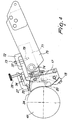
Figure 4 shows a further case, in which the mounting means of the holding device of the chambered doctor blade offigure 2 have been slightly changed with respect to the corresponding mounting means offigures 2 and3 . - In particular, the holding device is a holding
block 71 comprising, on its upper surface, a mounting means in the form of a protrudingclamp 72 and itscorresponding clamping screw 73 and, below the free end of theclaim 72, a threadedhole 78 for the clampingscrew 73. - The holding
block 71, as the holding device offigures 2-3 , is pivoted at 74 to asupport lever 75 of moving means for adjusting the position of the chambered doctor blade with respect to theprinting roller 4A. The moving means, preferably, are computer controlled for achieving a high precision positioning. - The
clamp 72 is located on the holdingblock 71 so that the free arm of the clamp is directed substantially towards the same direction of the front edge of the holdingblock 71, in order to clamp and fix the L-shaped support structure of the doctor blade to the holdingblock 71. - As it is apparent to the person skilled in the art, further mounting means different from those described above can be provided which are independent of the particular kind of doctor blade unit to be used in the rotogravure printing press, i.e. regardless of whether the doctor blade is chambered or non-chambered. For instance, snap-fit or geometrical couplings can be provided in the alternative, without altering the interchangeability features.
- The holding device may be provided with one or more of the mounting means listed above, as well as with their equivalents, so as to be adapted to support different doctor blade units.
-
Figure 5 shows a chambered doctor blade. The chambered doctor blade differs from the chambered doctor blade offigure 2 in that it further comprises ahandle 50 which is fixed to the upper surface of the L-shapedsupport structure 17. Preferably, twohandles 50 are provided on the L-shapedsupport structure 17, so that a user can easily grip the chambered doctor blade unit and remove it from the holding device, as well as fit it onto the holding device. - The operation of the invention is as follows. When the
rotogravure printing unit 100 is used with inks typically suitable for conventional rotogravure printing, a non-chambered doctor blade, such as that shown infigure 3 , is fixed to theholding device 2 and the moving means 5 are actuated so as to adjust and maintain the position of the non-chambered doctor blade with respect to the lateral surface of thegravure printing roller 4A. The ink pan beneath thegravure printing roller 4A is filled with ink, so that thegravure printing roller 4A can be wet with the ink during its rotation and the excess ink can be removed from the engraved surface of theroller 4A by means of the doctor of the non-chambered doctor blade unit before printing the film or web material supplied by the pressing roller. - When a different printing operation is needed, for instance an operation in which an ink having a fast drying must be used, the moving
means 5 are actuated so as to move the non-chambered doctor blade unit away from the printing roller, in the non-operational position, and the user can easily disassemble the non-chambered doctor blade and its support structure from the holding device, e.g. by removing thescrew 69 and lifting the non-chambered doctor blade unit by means of the handles fixed to its support structure. The ink pan is emptied from the ink used in the previous printing cycle or can be moved away from theprinting roller 4A. - Then, the chambered doctor blade, such as that shown in
figure 5 , is brought and fitted onto the holdingdevice 2 by means of thehandles 50 and is finally fixed to the holding device, e.g. by means of thescrew 38 in the same threadedhole 40 of the holdingblock 41. - Finally, after having connected the chamber of the chambered doctor blade unit to the
ink tank 6 by means ofhoses 8 and 10, the moving means are actuated so as to bring the holding device and the chambered doctor blade unit in the operational position, i.e. at the periphery of thegravure printing roller 4A. Accordingly, the ink is supplied to theprinting roller 4A at an angular position which is closer to the pressing roller than the position of the ink pan, allowing to use inks that could not be otherwise used in a rotogravure printing unit. - It has been shown that the invention achieves the intended aim and objects. In particular, a doctor blade assembly has been provided which allows different inks or substances to be used within the same printing unit, because of the provision of mounting means which allow different kinds of doctor blade units to be installed thereon.
- The doctor blade interchangeability which characterizes the doctor blade assembly according to the invention allows a printing unit to be easily switched from one printing mode to another printing mode. An important consequence is that the cleaning operations of printing presses such as rotogravure printing presses are drastically reduced, because such printing presses can also operate with chambered doctor blade units, without causing ink splashes and other well known drawbacks due to the interaction between the printing roller and the ink pan or vessel beneath the roller.
- Moreover, the provision of a doctor blade assembly according to the invention does not need any substantial alteration of the mechanical structure and of the operating software of existing printing unit, which can be easily updated with such assembly.
- Although the assembly according to the invention has been conceived in particular for gravure or rotogravure printing presses, it can nonetheless also be used for other kinds of rotary printing presses which use doctor blades.
- The invention is defined by the appended claims.
Claims (7)
- Doctor blade assembly (101) for printing units, in particular for rotogravure printing units (100), comprising- a first doctor blade unit (1), comprising a single doctor blade and a first support structure (17, 51)
a second doctor blade unit comprising a chambered doctor blade and a second support structure- a holding device (2, 41, 71) comprising a mounting means (38, 40; 72), for a support structure and- a moving means (5) of the holding device (2, 41, 71),characterized in that the same mounting means (38, 40; 72) is adapted to fix alternatively the support structure (17, 51) of the first doctor blade unit (20, 24) and the support structure of the second doctor blade unit (54), so as to allow different inks to be used within the same printing unit (100). - The doctor blade assembly according to claim 1, characterized in that each support structure (17, 51) is substantially L-shaped, at least one arm (37, 68) of the L-shaped support structure (17, 51) being detachably fixable to said holding device (2) by means of said mounting means (38, 40; 72).
- The doctor blade assembly according to claim 1 or 2, characterized in that said mounting means (38, 40; 72) comprise one or more of: at least one screw, a clamp, a snap-fit coupling, a geometrical coupling.
- The doctor blade assembly according to one or more of the preceding claims, characterized in that each support structure (17, 51) comprises at least one handle (50).
- A rotogravure printing unit (100) comprising at least one gravure printing roller (4A) and at least one pressing roller (4B) adjacent to said gravure printing roller (4A), characterized in that said rotogravure printing unit (100) comprises the doctor blade assembly (101) according to one or more of the preceding claims.
- The rotogravure printing unit of claim 5, wherein a chambered doctor blade is removably fixable to said moving means (5) by virtue of said mounting means (38,40; 72), the moving means (5) being suitable to adjust the position of said chambered doctor blade with respect to the lateral surface of said gravure printing roller (4A).
- A method for changing doctor blades in a printing unit (100) incorporating a doctor blade assembly (101) according to any one of the preceding claims, the method allowing different inks to be used within the same printing unit and comprising the steps of:- actuating the moving means (5) so as to move a single doctor blade unit (54) away from a printing roller (4A),- disassembling the single doctor blade unit (54) with its support structure (51) from the mounting means of a holding device (2),- lifting the single doctor blade unit (54),- bringing and fitting a chambered doctor blade unit (20, 24) with its support structure onto the same mounting means the holding device (2),- fixing the chambered doctor blade unit (20, 24) of to the holding device (2), and- actuating the moving means (5) so as to bring the holding device (2) and the chambered doctor blade unit (20, 24) at the periphery of the printing roller (4A).
Priority Applications (4)
| Application Number | Priority Date | Filing Date | Title |
|---|---|---|---|
| EP07020393.0A EP2055481B1 (en) | 2007-10-18 | 2007-10-18 | Doctor blade assembly and a method for allowing different inks to be used |
| ES07020393.0T ES2640222T3 (en) | 2007-10-18 | 2007-10-18 | Scraper blade assembly and method that allows using different inks |
| US12/252,464 US20090101028A1 (en) | 2007-10-18 | 2008-10-16 | Doctor blade assembly |
| US13/367,176 US8245636B2 (en) | 2007-10-18 | 2012-02-06 | Interchangeable doctor blade assembly |
Applications Claiming Priority (1)
| Application Number | Priority Date | Filing Date | Title |
|---|---|---|---|
| EP07020393.0A EP2055481B1 (en) | 2007-10-18 | 2007-10-18 | Doctor blade assembly and a method for allowing different inks to be used |
Publications (2)
| Publication Number | Publication Date |
|---|---|
| EP2055481A1 EP2055481A1 (en) | 2009-05-06 |
| EP2055481B1 true EP2055481B1 (en) | 2017-08-16 |
Family
ID=40374918
Family Applications (1)
| Application Number | Title | Priority Date | Filing Date |
|---|---|---|---|
| EP07020393.0A Active EP2055481B1 (en) | 2007-10-18 | 2007-10-18 | Doctor blade assembly and a method for allowing different inks to be used |
Country Status (3)
| Country | Link |
|---|---|
| US (2) | US20090101028A1 (en) |
| EP (1) | EP2055481B1 (en) |
| ES (1) | ES2640222T3 (en) |
Families Citing this family (9)
| Publication number | Priority date | Publication date | Assignee | Title |
|---|---|---|---|---|
| AT502824B1 (en) * | 2006-02-16 | 2007-06-15 | Bartelmuss Klaus Ing | Doctor blade holder detachable fixing device for paper production plant, has holder fixable at support in operating position, and pressure hose provided between holder and support and clamping holder to support |
| ES2431894B1 (en) | 2012-04-26 | 2014-09-03 | Comexi Group Industries, Sau | System for applying printing liquid or printing aid to a gravure roller |
| EP2969568A4 (en) * | 2013-03-13 | 2016-11-23 | Probity Engineering Llc | Ink fountain apparatus and method of adjusting ink flow for a flexographic printing apparatus |
| CN105874122B (en) * | 2013-11-06 | 2019-10-18 | 卡丹特公司 | Doctor blade frame system |
| JP6183232B2 (en) * | 2014-01-30 | 2017-08-23 | 日本ゼオン株式会社 | Gravure coating equipment |
| US20170239937A1 (en) * | 2016-02-24 | 2017-08-24 | Paul Joseph ROMANELLI | Apparatus includes housing assembly, mountable to printing machine cylinder, for supporting doctor blade and impression roller |
| KR102198728B1 (en) * | 2017-03-29 | 2021-01-05 | 닛토덴코 가부시키가이샤 | Coating apparatus and method for producing coating film |
| EP3957386A1 (en) * | 2020-08-18 | 2022-02-23 | UMICORE AG & Co. KG | Catalyst for reducing ammonia emissions |
| CN115257178B (en) * | 2022-08-30 | 2024-03-15 | 广东旺盈环保包装实业有限公司 | Scraper component of color box printing machine |
Family Cites Families (30)
| Publication number | Priority date | Publication date | Assignee | Title |
|---|---|---|---|---|
| GB8708401D0 (en) * | 1987-04-08 | 1987-05-13 | Vickers Plc | Lithographic printing |
| US4789432A (en) * | 1987-06-08 | 1988-12-06 | Thermo Electron Web Systems, Inc. | Doctoring apparatus |
| DE3832216C1 (en) * | 1988-09-22 | 1990-05-31 | Man Roland Druckmaschinen Ag, 6050 Offenbach, De | |
| DE3832160A1 (en) * | 1988-09-22 | 1990-04-12 | Roland Man Druckmasch | RAKELFARBWERK |
| DE4012618A1 (en) * | 1990-04-20 | 1991-10-24 | Roland Man Druckmasch | RAKELFARBWERK |
| CA2048120A1 (en) * | 1990-08-06 | 1992-02-07 | William J. Drasler | Thrombectomy method and device |
| US6676627B1 (en) * | 1990-08-06 | 2004-01-13 | Possis Medical, Inc. | Crossflow thrombectomy catheter and system |
| DE4102545A1 (en) * | 1991-01-29 | 1992-07-30 | Basf Ag | METHOD FOR GELING, PRELIMINATING AND GIVING BARE AND FUR BLOSSES AND FOR LEAVING LEATHER AND FUR |
| DE4126886A1 (en) * | 1991-08-14 | 1993-02-18 | Hp Medica Gmbh | RINSING CATHETER |
| DE4201992A1 (en) * | 1992-01-25 | 1993-07-29 | Hp Medica Gmbh Fuer Medizintec | HIGH PRESSURE LIQUID DISPENSOR FOR DISPENSING STERILE LIQUID |
| DE4213669C2 (en) * | 1992-04-25 | 1995-06-08 | Koenig & Bauer Ag | Device for adjusting a doctor blade |
| US5406887A (en) * | 1993-01-15 | 1995-04-18 | Paper Converting Machine Company | Apparatus and method for doctor blade replacement in a flexographic press |
| CA2127637C (en) * | 1993-07-26 | 2006-01-03 | Scott Bair | Fluid jet surgical cutting tool |
| US5527330A (en) * | 1994-08-18 | 1996-06-18 | United States Surgical Corporation | Fluid cutting instrument |
| US5944686A (en) * | 1995-06-07 | 1999-08-31 | Hydrocision, Inc. | Instrument for creating a fluid jet |
| US6216573B1 (en) * | 1995-06-07 | 2001-04-17 | Hydrocision, Inc. | Fluid jet cutting system |
| DE19624440A1 (en) | 1996-06-19 | 1998-01-02 | Roland Man Druckmasch | Device for filling recesses in a cylinder, doctor devices therefor and methods for changing them |
| FR2764843B1 (en) * | 1997-06-19 | 1999-08-20 | Martin Sa | MULTIFUNCTIONAL INKING SYSTEM FOR A FLEXOGRAPHIC PRINTER |
| US6497572B2 (en) * | 1997-07-09 | 2002-12-24 | Surgijet, Inc. | Apparatus for dental treatment using high pressure liquid jet |
| US6224378B1 (en) * | 1997-07-09 | 2001-05-01 | Surgijet, Inc. | Method and apparatus for dental treatment using high pressure liquid jet |
| US5980692A (en) * | 1997-12-22 | 1999-11-09 | Thermo Web Systems, Inc. | Removable doctor blade holder |
| DE19915426A1 (en) * | 1999-04-06 | 2000-11-09 | Pein Andreas Medizintech Gmbh | Water jet device for separating a biological structure |
| AU762106B2 (en) * | 1999-06-22 | 2003-06-19 | Tresu Production A/S | Doctor blade system |
| US6689101B2 (en) * | 2000-05-22 | 2004-02-10 | Pharmacia Ab | Medical arrangement |
| WO2002095234A1 (en) * | 2001-04-27 | 2002-11-28 | Hydrocision, Inc. | High pressure pumping cartridges for medical and surgical pumping and infusion applications |
| US6796231B2 (en) * | 2002-09-20 | 2004-09-28 | The Provident Group | Shield for doctor blade holder |
| DE20309616U1 (en) * | 2003-06-20 | 2003-11-13 | Pein, Andreas, 23911 Einhaus | Water jet device for separating a biological structure |
| US20060100569A1 (en) * | 2004-11-11 | 2006-05-11 | Depuy Mitek, Inc | Methods and devices for selective bulk removal and precision sculpting of tissue |
| DE102004060881A1 (en) * | 2004-12-17 | 2006-06-29 | Man Roland Druckmaschinen Ag | Exchange unit for a printing press |
| US20060149193A1 (en) * | 2005-01-05 | 2006-07-06 | Biomec, Inc. | High pressure liquid jet ablation of tissue and apparatus |
-
2007
- 2007-10-18 EP EP07020393.0A patent/EP2055481B1/en active Active
- 2007-10-18 ES ES07020393.0T patent/ES2640222T3/en active Active
-
2008
- 2008-10-16 US US12/252,464 patent/US20090101028A1/en not_active Abandoned
-
2012
- 2012-02-06 US US13/367,176 patent/US8245636B2/en not_active Expired - Fee Related
Non-Patent Citations (1)
| Title |
|---|
| None * |
Also Published As
| Publication number | Publication date |
|---|---|
| EP2055481A1 (en) | 2009-05-06 |
| US20090101028A1 (en) | 2009-04-23 |
| US20120132095A1 (en) | 2012-05-31 |
| US8245636B2 (en) | 2012-08-21 |
| ES2640222T3 (en) | 2017-11-02 |
Similar Documents
| Publication | Publication Date | Title |
|---|---|---|
| EP2055481B1 (en) | Doctor blade assembly and a method for allowing different inks to be used | |
| KR960012753B1 (en) | Coating apparatus for sheet-feed rotary offset printing press | |
| JP3037211B2 (en) | Printing cylinder recess filling device, recess filling blade device, and blade device replacement method | |
| JP4163923B2 (en) | Intaglio printing machine | |
| EP3135492A2 (en) | Numbering and imprinting machine | |
| US5375522A (en) | Method and apparatus for washing a printing press in conjunction with a damping unit | |
| JP2008201119A5 (en) | ||
| EP1926600B1 (en) | Textile printer | |
| US5452660A (en) | Washing device selectively engageable with plural inking paths | |
| EP0085439B1 (en) | Overvarnish apparatus for decorator machine | |
| EP2657020B1 (en) | Articulated doctor blade assembly for printing groups | |
| JP2019136958A (en) | Gravure printing method and squeegee used therefor | |
| JP2001277748A (en) | Printing device for printer | |
| JP4932999B2 (en) | Inking device of printing machine | |
| CN209600052U (en) | A kind of connection structure of flexible printing press doctor | |
| EP3807092B1 (en) | Inking cartridge for a rotogravure press with optimal configurations for several types of ink | |
| US5018444A (en) | Ink applying system for a printing apparatus | |
| EP3807091B1 (en) | Inking system for a rotogravure press with optimal configurations for several types of ink and method for configuring the inking system | |
| JPH0137272B2 (en) | ||
| US8327763B2 (en) | Printing couple of a rotary printing press and a method for washing a dampening unit of a printing couple | |
| JPH043802Y2 (en) | ||
| JP3416640B2 (en) | Ink supply device for printing equipment | |
| JP3495506B2 (en) | Printing machine ink scraper | |
| JP2005067044A (en) | Ink supply device for anilox roll and flexographic press using the same | |
| JPH0818429B2 (en) | Planographic printing apparatus and method thereof |
Legal Events
| Date | Code | Title | Description |
|---|---|---|---|
| PUAI | Public reference made under article 153(3) epc to a published international application that has entered the european phase |
Free format text: ORIGINAL CODE: 0009012 |
|
| AK | Designated contracting states |
Kind code of ref document: A1 Designated state(s): AT BE BG CH CY CZ DE DK EE ES FI FR GB GR HU IE IS IT LI LT LU LV MC MT NL PL PT RO SE SI SK TR |
|
| AX | Request for extension of the european patent |
Extension state: AL BA HR MK RS |
|
| 17P | Request for examination filed |
Effective date: 20091016 |
|
| 17Q | First examination report despatched |
Effective date: 20091120 |
|
| AKX | Designation fees paid |
Designated state(s): AT BE BG CH CY CZ DE DK EE ES FI FR GB GR HU IE IS IT LI LT LU LV MC MT NL PL PT RO SE SI SK TR |
|
| RAP1 | Party data changed (applicant data changed or rights of an application transferred) |
Owner name: BOBST ITALIA S.P.A. |
|
| REG | Reference to a national code |
Ref country code: DE Ref legal event code: R079 Ref document number: 602007051981 Country of ref document: DE Free format text: PREVIOUS MAIN CLASS: B41F0031050000 Ipc: B41F0009100000 |
|
| RIC1 | Information provided on ipc code assigned before grant |
Ipc: B41F 9/10 20060101AFI20170201BHEP Ipc: B41F 31/20 20060101ALI20170201BHEP Ipc: B41F 31/05 20060101ALI20170201BHEP |
|
| GRAP | Despatch of communication of intention to grant a patent |
Free format text: ORIGINAL CODE: EPIDOSNIGR1 |
|
| INTG | Intention to grant announced |
Effective date: 20170424 |
|
| GRAS | Grant fee paid |
Free format text: ORIGINAL CODE: EPIDOSNIGR3 |
|
| GRAA | (expected) grant |
Free format text: ORIGINAL CODE: 0009210 |
|
| AK | Designated contracting states |
Kind code of ref document: B1 Designated state(s): AT BE BG CH CY CZ DE DK EE ES FI FR GB GR HU IE IS IT LI LT LU LV MC MT NL PL PT RO SE SI SK TR |
|
| REG | Reference to a national code |
Ref country code: GB Ref legal event code: FG4D |
|
| REG | Reference to a national code |
Ref country code: CH Ref legal event code: EP |
|
| REG | Reference to a national code |
Ref country code: IE Ref legal event code: FG4D |
|
| REG | Reference to a national code |
Ref country code: AT Ref legal event code: REF Ref document number: 918660 Country of ref document: AT Kind code of ref document: T Effective date: 20170915 |
|
| REG | Reference to a national code |
Ref country code: DE Ref legal event code: R096 Ref document number: 602007051981 Country of ref document: DE |
|
| REG | Reference to a national code |
Ref country code: ES Ref legal event code: FG2A Ref document number: 2640222 Country of ref document: ES Kind code of ref document: T3 Effective date: 20171102 |
|
| REG | Reference to a national code |
Ref country code: NL Ref legal event code: MP Effective date: 20170816 |
|
| REG | Reference to a national code |
Ref country code: LT Ref legal event code: MG4D |
|
| REG | Reference to a national code |
Ref country code: AT Ref legal event code: MK05 Ref document number: 918660 Country of ref document: AT Kind code of ref document: T Effective date: 20170816 |
|
| PG25 | Lapsed in a contracting state [announced via postgrant information from national office to epo] |
Ref country code: SE Free format text: LAPSE BECAUSE OF FAILURE TO SUBMIT A TRANSLATION OF THE DESCRIPTION OR TO PAY THE FEE WITHIN THE PRESCRIBED TIME-LIMIT Effective date: 20170816 Ref country code: NL Free format text: LAPSE BECAUSE OF FAILURE TO SUBMIT A TRANSLATION OF THE DESCRIPTION OR TO PAY THE FEE WITHIN THE PRESCRIBED TIME-LIMIT Effective date: 20170816 Ref country code: AT Free format text: LAPSE BECAUSE OF FAILURE TO SUBMIT A TRANSLATION OF THE DESCRIPTION OR TO PAY THE FEE WITHIN THE PRESCRIBED TIME-LIMIT Effective date: 20170816 Ref country code: LT Free format text: LAPSE BECAUSE OF FAILURE TO SUBMIT A TRANSLATION OF THE DESCRIPTION OR TO PAY THE FEE WITHIN THE PRESCRIBED TIME-LIMIT Effective date: 20170816 Ref country code: FI Free format text: LAPSE BECAUSE OF FAILURE TO SUBMIT A TRANSLATION OF THE DESCRIPTION OR TO PAY THE FEE WITHIN THE PRESCRIBED TIME-LIMIT Effective date: 20170816 |
|
| PG25 | Lapsed in a contracting state [announced via postgrant information from national office to epo] |
Ref country code: BG Free format text: LAPSE BECAUSE OF FAILURE TO SUBMIT A TRANSLATION OF THE DESCRIPTION OR TO PAY THE FEE WITHIN THE PRESCRIBED TIME-LIMIT Effective date: 20171116 Ref country code: IS Free format text: LAPSE BECAUSE OF FAILURE TO SUBMIT A TRANSLATION OF THE DESCRIPTION OR TO PAY THE FEE WITHIN THE PRESCRIBED TIME-LIMIT Effective date: 20171216 Ref country code: PL Free format text: LAPSE BECAUSE OF FAILURE TO SUBMIT A TRANSLATION OF THE DESCRIPTION OR TO PAY THE FEE WITHIN THE PRESCRIBED TIME-LIMIT Effective date: 20170816 Ref country code: LV Free format text: LAPSE BECAUSE OF FAILURE TO SUBMIT A TRANSLATION OF THE DESCRIPTION OR TO PAY THE FEE WITHIN THE PRESCRIBED TIME-LIMIT Effective date: 20170816 Ref country code: GR Free format text: LAPSE BECAUSE OF FAILURE TO SUBMIT A TRANSLATION OF THE DESCRIPTION OR TO PAY THE FEE WITHIN THE PRESCRIBED TIME-LIMIT Effective date: 20171117 |
|
| PG25 | Lapsed in a contracting state [announced via postgrant information from national office to epo] |
Ref country code: CZ Free format text: LAPSE BECAUSE OF FAILURE TO SUBMIT A TRANSLATION OF THE DESCRIPTION OR TO PAY THE FEE WITHIN THE PRESCRIBED TIME-LIMIT Effective date: 20170816 Ref country code: DK Free format text: LAPSE BECAUSE OF FAILURE TO SUBMIT A TRANSLATION OF THE DESCRIPTION OR TO PAY THE FEE WITHIN THE PRESCRIBED TIME-LIMIT Effective date: 20170816 Ref country code: RO Free format text: LAPSE BECAUSE OF FAILURE TO SUBMIT A TRANSLATION OF THE DESCRIPTION OR TO PAY THE FEE WITHIN THE PRESCRIBED TIME-LIMIT Effective date: 20170816 |
|
| REG | Reference to a national code |
Ref country code: DE Ref legal event code: R097 Ref document number: 602007051981 Country of ref document: DE |
|
| PG25 | Lapsed in a contracting state [announced via postgrant information from national office to epo] |
Ref country code: EE Free format text: LAPSE BECAUSE OF FAILURE TO SUBMIT A TRANSLATION OF THE DESCRIPTION OR TO PAY THE FEE WITHIN THE PRESCRIBED TIME-LIMIT Effective date: 20170816 Ref country code: MC Free format text: LAPSE BECAUSE OF FAILURE TO SUBMIT A TRANSLATION OF THE DESCRIPTION OR TO PAY THE FEE WITHIN THE PRESCRIBED TIME-LIMIT Effective date: 20170816 Ref country code: SK Free format text: LAPSE BECAUSE OF FAILURE TO SUBMIT A TRANSLATION OF THE DESCRIPTION OR TO PAY THE FEE WITHIN THE PRESCRIBED TIME-LIMIT Effective date: 20170816 |
|
| REG | Reference to a national code |
Ref country code: CH Ref legal event code: PL |
|
| PLBE | No opposition filed within time limit |
Free format text: ORIGINAL CODE: 0009261 |
|
| STAA | Information on the status of an ep patent application or granted ep patent |
Free format text: STATUS: NO OPPOSITION FILED WITHIN TIME LIMIT |
|
| 26N | No opposition filed |
Effective date: 20180517 |
|
| GBPC | Gb: european patent ceased through non-payment of renewal fee |
Effective date: 20171116 |
|
| REG | Reference to a national code |
Ref country code: IE Ref legal event code: MM4A |
|
| REG | Reference to a national code |
Ref country code: FR Ref legal event code: ST Effective date: 20180629 |
|
| PG25 | Lapsed in a contracting state [announced via postgrant information from national office to epo] |
Ref country code: CH Free format text: LAPSE BECAUSE OF NON-PAYMENT OF DUE FEES Effective date: 20171031 Ref country code: LU Free format text: LAPSE BECAUSE OF NON-PAYMENT OF DUE FEES Effective date: 20171018 Ref country code: LI Free format text: LAPSE BECAUSE OF NON-PAYMENT OF DUE FEES Effective date: 20171031 |
|
| REG | Reference to a national code |
Ref country code: BE Ref legal event code: MM Effective date: 20171031 |
|
| PG25 | Lapsed in a contracting state [announced via postgrant information from national office to epo] |
Ref country code: SI Free format text: LAPSE BECAUSE OF FAILURE TO SUBMIT A TRANSLATION OF THE DESCRIPTION OR TO PAY THE FEE WITHIN THE PRESCRIBED TIME-LIMIT Effective date: 20170816 Ref country code: BE Free format text: LAPSE BECAUSE OF NON-PAYMENT OF DUE FEES Effective date: 20171031 Ref country code: FR Free format text: LAPSE BECAUSE OF NON-PAYMENT OF DUE FEES Effective date: 20171031 |
|
| PG25 | Lapsed in a contracting state [announced via postgrant information from national office to epo] |
Ref country code: MT Free format text: LAPSE BECAUSE OF NON-PAYMENT OF DUE FEES Effective date: 20171018 |
|
| PG25 | Lapsed in a contracting state [announced via postgrant information from national office to epo] |
Ref country code: IE Free format text: LAPSE BECAUSE OF NON-PAYMENT OF DUE FEES Effective date: 20171018 |
|
| PG25 | Lapsed in a contracting state [announced via postgrant information from national office to epo] |
Ref country code: GB Free format text: LAPSE BECAUSE OF NON-PAYMENT OF DUE FEES Effective date: 20171116 |
|
| PG25 | Lapsed in a contracting state [announced via postgrant information from national office to epo] |
Ref country code: HU Free format text: LAPSE BECAUSE OF FAILURE TO SUBMIT A TRANSLATION OF THE DESCRIPTION OR TO PAY THE FEE WITHIN THE PRESCRIBED TIME-LIMIT; INVALID AB INITIO Effective date: 20071018 |
|
| PG25 | Lapsed in a contracting state [announced via postgrant information from national office to epo] |
Ref country code: CY Free format text: LAPSE BECAUSE OF NON-PAYMENT OF DUE FEES Effective date: 20170816 |
|
| PG25 | Lapsed in a contracting state [announced via postgrant information from national office to epo] |
Ref country code: TR Free format text: LAPSE BECAUSE OF FAILURE TO SUBMIT A TRANSLATION OF THE DESCRIPTION OR TO PAY THE FEE WITHIN THE PRESCRIBED TIME-LIMIT Effective date: 20170816 |
|
| PG25 | Lapsed in a contracting state [announced via postgrant information from national office to epo] |
Ref country code: PT Free format text: LAPSE BECAUSE OF FAILURE TO SUBMIT A TRANSLATION OF THE DESCRIPTION OR TO PAY THE FEE WITHIN THE PRESCRIBED TIME-LIMIT Effective date: 20170816 |
|
| PGFP | Annual fee paid to national office [announced via postgrant information from national office to epo] |
Ref country code: IT Payment date: 20230913 Year of fee payment: 17 |
|
| PGFP | Annual fee paid to national office [announced via postgrant information from national office to epo] |
Ref country code: ES Payment date: 20231109 Year of fee payment: 17 |
|
| PGFP | Annual fee paid to national office [announced via postgrant information from national office to epo] |
Ref country code: DE Payment date: 20230830 Year of fee payment: 17 |