EP1656168B1 - Aiguille avec valve d'obturation - Google Patents
Aiguille avec valve d'obturation Download PDFInfo
- Publication number
- EP1656168B1 EP1656168B1 EP04781223.5A EP04781223A EP1656168B1 EP 1656168 B1 EP1656168 B1 EP 1656168B1 EP 04781223 A EP04781223 A EP 04781223A EP 1656168 B1 EP1656168 B1 EP 1656168B1
- Authority
- EP
- European Patent Office
- Prior art keywords
- passageway
- plunger
- proximal
- disposed
- distal
- Prior art date
- Legal status (The legal status is an assumption and is not a legal conclusion. Google has not performed a legal analysis and makes no representation as to the accuracy of the status listed.)
- Not-in-force
Links
Images


Classifications
-
- A—HUMAN NECESSITIES
- A61—MEDICAL OR VETERINARY SCIENCE; HYGIENE
- A61M—DEVICES FOR INTRODUCING MEDIA INTO, OR ONTO, THE BODY; DEVICES FOR TRANSDUCING BODY MEDIA OR FOR TAKING MEDIA FROM THE BODY; DEVICES FOR PRODUCING OR ENDING SLEEP OR STUPOR
- A61M25/00—Catheters; Hollow probes
- A61M25/01—Introducing, guiding, advancing, emplacing or holding catheters
- A61M25/09—Guide wires
- A61M25/09041—Mechanisms for insertion of guide wires
-
- A—HUMAN NECESSITIES
- A61—MEDICAL OR VETERINARY SCIENCE; HYGIENE
- A61M—DEVICES FOR INTRODUCING MEDIA INTO, OR ONTO, THE BODY; DEVICES FOR TRANSDUCING BODY MEDIA OR FOR TAKING MEDIA FROM THE BODY; DEVICES FOR PRODUCING OR ENDING SLEEP OR STUPOR
- A61M39/00—Tubes, tube connectors, tube couplings, valves, access sites or the like, specially adapted for medical use
- A61M39/22—Valves or arrangement of valves
- A61M39/26—Valves closing automatically on disconnecting the line and opening on reconnection thereof
-
- A—HUMAN NECESSITIES
- A61—MEDICAL OR VETERINARY SCIENCE; HYGIENE
- A61M—DEVICES FOR INTRODUCING MEDIA INTO, OR ONTO, THE BODY; DEVICES FOR TRANSDUCING BODY MEDIA OR FOR TAKING MEDIA FROM THE BODY; DEVICES FOR PRODUCING OR ENDING SLEEP OR STUPOR
- A61M25/00—Catheters; Hollow probes
- A61M25/01—Introducing, guiding, advancing, emplacing or holding catheters
- A61M25/06—Body-piercing guide needles or the like
- A61M25/065—Guide needles
-
- A—HUMAN NECESSITIES
- A61—MEDICAL OR VETERINARY SCIENCE; HYGIENE
- A61M—DEVICES FOR INTRODUCING MEDIA INTO, OR ONTO, THE BODY; DEVICES FOR TRANSDUCING BODY MEDIA OR FOR TAKING MEDIA FROM THE BODY; DEVICES FOR PRODUCING OR ENDING SLEEP OR STUPOR
- A61M25/00—Catheters; Hollow probes
- A61M25/01—Introducing, guiding, advancing, emplacing or holding catheters
- A61M25/06—Body-piercing guide needles or the like
- A61M25/0693—Flashback chambers
-
- A—HUMAN NECESSITIES
- A61—MEDICAL OR VETERINARY SCIENCE; HYGIENE
- A61M—DEVICES FOR INTRODUCING MEDIA INTO, OR ONTO, THE BODY; DEVICES FOR TRANSDUCING BODY MEDIA OR FOR TAKING MEDIA FROM THE BODY; DEVICES FOR PRODUCING OR ENDING SLEEP OR STUPOR
- A61M39/00—Tubes, tube connectors, tube couplings, valves, access sites or the like, specially adapted for medical use
- A61M39/02—Access sites
- A61M39/06—Haemostasis valves, i.e. gaskets sealing around a needle, catheter or the like, closing on removal thereof
- A61M39/0606—Haemostasis valves, i.e. gaskets sealing around a needle, catheter or the like, closing on removal thereof without means for adjusting the seal opening or pressure
-
- A—HUMAN NECESSITIES
- A61—MEDICAL OR VETERINARY SCIENCE; HYGIENE
- A61M—DEVICES FOR INTRODUCING MEDIA INTO, OR ONTO, THE BODY; DEVICES FOR TRANSDUCING BODY MEDIA OR FOR TAKING MEDIA FROM THE BODY; DEVICES FOR PRODUCING OR ENDING SLEEP OR STUPOR
- A61M39/00—Tubes, tube connectors, tube couplings, valves, access sites or the like, specially adapted for medical use
- A61M39/02—Access sites
- A61M39/06—Haemostasis valves, i.e. gaskets sealing around a needle, catheter or the like, closing on removal thereof
- A61M39/0693—Haemostasis valves, i.e. gaskets sealing around a needle, catheter or the like, closing on removal thereof including means for seal penetration
-
- A—HUMAN NECESSITIES
- A61—MEDICAL OR VETERINARY SCIENCE; HYGIENE
- A61M—DEVICES FOR INTRODUCING MEDIA INTO, OR ONTO, THE BODY; DEVICES FOR TRANSDUCING BODY MEDIA OR FOR TAKING MEDIA FROM THE BODY; DEVICES FOR PRODUCING OR ENDING SLEEP OR STUPOR
- A61M5/00—Devices for bringing media into the body in a subcutaneous, intra-vascular or intramuscular way; Accessories therefor, e.g. filling or cleaning devices, arm-rests
- A61M5/178—Syringes
- A61M5/31—Details
- A61M5/32—Needles; Details of needles pertaining to their connection with syringe or hub; Accessories for bringing the needle into, or holding the needle on, the body; Devices for protection of needles
- A61M5/3293—Needles; Details of needles pertaining to their connection with syringe or hub; Accessories for bringing the needle into, or holding the needle on, the body; Devices for protection of needles characterised by features of the needle hub
Definitions
- the present invention relates to a device with a combination passageway and valve as described in the preamble part of independent claim 1, and a needle assembly having a combination passageway and valve device of this kind.
- Catheters for the introduction or removal of fluids may be located in various venous locations and cavities throughout the body for introducing or removing fluids. Such catheterization may be performed by using a single catheter having multiple lumens. A typical example of a multiple lumen catheter is a dual lumen catheter in which one lumen introduces fluids and one lumen removes fluids. Catheterization may also be performed by using separate, single lumen catheters inserted through two different incisions into an area to be catheterized. Such multiple catheter assemblies are known as Tesio® catheters.
- the vessel is identified by aspiration using an introducer device, such as a syringe having a long hollow needle in accordance with the Seldinger technique.
- an introducer device such as a syringe having a long hollow needle in accordance with the Seldinger technique.
- a needle is attached to a syringe and inserted under the patient's skin, with the plunger being withdrawn as the needle is inserted.
- the syringe body is removed and a thin guide wire is introduced through the needle lumen and into the interior of the vessel.
- the needle is then removed, leaving a portion of the guide wire within the vessel and the remainder projecting outwardly to a point beyond the surface of the patient's skin.
- Other guide wire introducing devices and syringes are also available.
- the catheter is inserted by the physician over the guide wire using one of several known techniques.
- each catheter may be inserted in two separate veins.
- each catheter may be inserted in two different locations of the same vein, such as the internal jugular vein or in a single insertion site as described in U.S. Pat. No. 5,624,413 .
- the introducer sheath is simply a large, stiff, thin-walled tube which serves as a temporary conduit for the permanent catheter which is being placed.
- the introducer sheath is positioned by placing a dilator device inside of the introducer and passing both the dilator and the introducer together into the vessel over the guide wire.
- the guide wire which is partially within the vessel after insertion as described above, and the dilator are then removed, leaving the thin-walled introducer sheath in place.
- the catheter is then placed through the introducer sheath.
- the first step is aspirating the vessel or area to be catheterized prior to introducing the guide wire.
- This is often troublesome, especially when aspirating blood vessels, due to the flashback of blood.
- Arterial blood may spurt from the needle insertion point with considerable force and may contact a physician or other attendant assisting the physician, causing the risk of contamination with blood borne pathogens, such as HIV virus or hepatitis.
- a second problem, which is of greater concern to the patient, is exposing certain venous blood vessels or other body cavities to atmospheric pressure. Veins are often under negative pressure as blood is being drawn back to the thoracic cavity due to the process of inspiration during the breathing cycle, and a hole in a venous blood vessel could lead to air being drawn into the blood vessel, creating an air embolism.
- WO 03/002182 A1 discloses a guide wire insertion device for a catheter, including a needle portion with a hollow body, a cap portion mounted on a rear (proximal) end of the hollow body, and a valve mounted in the hollow body. The valve is opened by a rod portion which extends distally beyond the cap portion.
- US 4,842,591 teaches a connector device with a one-way septum valve, which includes a slit, resilient septum mounted within the connector, and a moveable plug spaced a short distance from the septum and adapted to move forward slightly upon contact with the injection device.
- U.S. Patent No. 5,613,663 discloses a valve device within a two-piece housing that requires the valve to be assembled within the device prior to assembly of the two pieces that comprise the housing.
- the valve disclosed in this patent requires arterial blood pressure to close the valve. It would be beneficial to provide a valve that is housed in a one-piece housing to facilitate manufacturing of the device, and that includes a valve closure mechanism that does not require arterial blood pressure to close the valve.
- the invention overcomes the problems of prior art by means of providing a combination passageway and valve device, and a needle assembly, as described in claims 1 and 9, respectively.
- Advantageous developments of the invention are described in the dependent claims.
- the present invention provides a needle assembly comprising a hollow needle having a pointed distal end and a proximal end.
- the assembly also includes a needle hub having a distal hub end fixedly connected to the needle, a proximal hub end having an opening, and a passageway extending therethrough between the distal end and the proximal end.
- a valve is disposed within the passageway, wherein the valve comprises a sealing member having at least one through-opening disposed therein and a plunger disposed proximate the sealing member and slidable between a first position wherein the at least one through-opening is closed such that the hollow needle and the proximal hub end are not in fluid communication with each other and a second position wherein the plunger biases the at least one through-opening to an open position, such that the hollow needle and the proximal hub end are in fluid communication with each other.
- the present application describes also a method of inserting a guide wire into a blood vessel.
- the method comprises: providing the needle assembly comprising a hollow needle having a pointed distal end and a proximal end.
- the assembly also includes a needle hub having a distal hub end fixedly connected to the needle, a proximal hub end having an opening, and a passageway extending therethrough between the distal end and the proximal end.
- a valve is disposed within the passageway, wherein the valve comprises a sealing member having at least one through-opening disposed therein and a plunger disposed proximate the sealing member and slidable between a first position wherein the at least one through-opening is closed such that the hollow needle and the proximal hub end are not in fluid communication with each other and a second position wherein the plunger biases the at least one through-opening to an open position, such that the hollow needle and the proximal hub end are in fluid communication with each other.
- the method also includes: providing a body having a luer connector extending therefrom; providing a guide wire having a distal end; releasably connecting the body to the proximal end of the hub, wherein the luer connector disposes the plunger in a distal direction, wherein the plunger biases the at least one through-opening from a closed position to an open position; inserting the pointed distal end of the needle into the blood vessel; confirming proper placement of the needle in the blood vessel by drawing blood into the body; removing the body from the needle assembly, wherein the luer connector is disposed away from the plunger, wherein the sealing member biases the plunger in a proximal direction, and wherein the at least one through-opening returns to the closed position; inserting the distal end of the guide wire into the passageway, through the at least one through-opening, through the hollow needle and into the blood vessel; and removing the needle assembly from the blood vessel by sliding the needle assembly proximally along the guide wire.
- the present invention also provides a needle assembly comprising a hollow needle having a pointed distal end, a proximal end, and a longitudinal axis extending between the distal end and the proximal end.
- a needle hub having a distal hub end is fixedly connected to the needle.
- the needle hub includes a proximal hub end having an opening and a passageway extending therethrough along the longitudinal axis between the distal hub end and the proximal hub end.
- a valve is disposed within the passageway.
- the valve comprises a sealing member having at least one through-opening disposed along the longitudinal axis and a plunger disposed proximate the sealing member and slidable between a first position wherein the at least one through-opening is closed such that the hollow needle and the proximal hub end are not in fluid communication with each other and a second position wherein the plunger biases the at least one through-opening to an open position, such that the hollow needle and the proximal hub end are in fluid communication with each other.
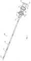
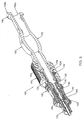
- Fig. 1 is a side profile view of a needle assembly according to the present invention.
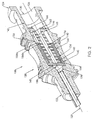
- Fig. 2 is an enlarged perspective view, in section, of the needle hub shown in Fig. 1 , with a hub valve in a closed position.
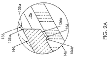
- Fig. 2A is a greatly enlarged partial side profile view of Fig. 2 , in section, showing retaining portions of the valve.
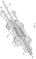
- Fig. 3 is a perspective view, in section, of the needle hub of Fig. 2 , with a syringe opening the hub valve.
- Fig. 4 is a perspective view, in section, of the needle hub of Fig. 2 , with a guide wire inserted through the hub valve.
- Fig. 5 is a perspective view, in section, of the needle hub of Fig. 2 , with a bulb opening the hub valve.
- Fig. 6 is a perspective view, in section, of an alternate embodiment of the present invention.
- distal and proximal refer to the insertion end and the connecting end, respectively, of the needle assembly according to the present invention.
- the terminology includes the words above specifically mentioned, derivatives thereof and words of similar import.
- the embodiments illustrated below are not intended to be exhaustive or to limit the invention to the precise form disclosed. These embodiments are chosen and described to best explain the principle of the invention and its application and practical use and to enable others skilled in the art to best utilize the invention.
- the needle assembly 100 includes a needle 110 having a beveled distal tip 112 and a proximal end 114.
- the needle 110 includes a hollow cannulating portion 116 that extends between the distal tip 112 and the proximal end 114.
- the needle 110 is constructed from stainless steel or some other suitable material.
- a generally hollow needle hub 120 is fixedly connected to the proximal end 114 of the needle 110.
- the hub 120 is of one-piece construction for ease of manufacture and cost issues.
- the hub 120 includes a distal end 122 that is fixedly connected to and encompasses the proximal end 114 of the needle 110.
- the hub 120 also includes an open proximal end 124 and a passageway 126 extending between the proximal end 124 and the distal end 122, and in fluid communication with the cannulating portion 116 of the needle 110.
- a longitudinal axis 127 extends between the distal end 122 and the proximal end 124 along the passageway 126 and through the needle 110 between the distal tip 112 and the proximal end 114.
- a distal end 128 of the passageway 126 is conically tapered from a larger diameter D1 to a smaller diameter D2 that is generally the same size as the diameter of the cannulating portion 116 of the needle 110.
- a proximal end 130 of the passageway 126 has a diameter D3 that is sized and tapered to accept a standard luer lock fitting, as is well known by those skilled in the art.
- the proximal end 124 also includes male threads 132 to facilitate connection of the needle assembly 100 to an external device, such as a syringe.
- a retaining ring 133 is disposed within the passageway 126 between the distal end 128 and the proximal end 130.
- the retaining ring 133 includes a tapered proximal face 133a and a straight distal face 133b that extends generally perpendicular to the length of the passageway 126.
- the hub 120 is constructed from Cyrolite® Med 2 Acrylic-Based, produced by Cyro Industries, Orange, CT, although those skilled in the art will recognize that other suitable materials may be used.
- a valve 140 is disposed within the passageway 126.
- the valve 140 includes a seal 142, a support member 144, and a plunger 146.
- the seal 142 is disposed proximate to the distal end 128 of the passageway 126 and is generally annularly shaped, with a generally tubular side wall 147 and a closeable distal portion 148 that seals the passageway 126 to prevent fluid flow therethrough.
- the distal portion 148 includes a plurality of through-openings 150 that extend generally radially from the center of the distal portion 148, preferably generally evenly radially spaced, toward the sidewall 147.
- the seal 142 is generally disposed about the longitudinal axis 127, with the longitudinal axis 127 extending through the intersection of the through-openings 150 in the distal portion 148 of the seal 142.
- three through-openings 150 are present (only one through-opening 150 is shown in Fig. 2 ), although those skilled in the art will recognize that more or less than three through-openings 150 may be used.
- the seal 142 is constructed from silicon or some other suitable material so that, when the valve 140 is opened, as will be described in more detail later herein, the through-openings 150 allow the distal portion 148 to open, allowing fluid flow through the seal 142.
- the support member 144 is disposed within the passageway 126 just proximal of the seal 142.
- the support member 144 has a generally annularly shaped cross section and includes a recessed distal portion 154 sized to allow the sidewall 147 of the seal 142 to snugly surround the recessed distal portion 154 and to bias the seal 142 to a most distal position within the passageway 126.
- the retaining ring 133 allows the support member 144 to be inserted distally into the passageway 126, but restrains the support member 144 from being removed proximally from the passageway 126. Referring now to Fig.
- the support member 144 further includes a retaining ring 156 disposed at a proximal end 158 of the support member 144.
- the retaining ring 156 includes a tapered proximal face 156a and a straight distal face 156b that extends generally perpendicular to the length of the passageway 126.
- the support member 144 is constructed from pellethane, Cyrolite®, or some other suitable material.
- the plunger 146 includes a distal portion 160 that is disposed within the support member 144 and a proximal portion 162 that is disposed within the passageway 126 proximal of the support member 144.
- the plunger 146 has a generally annularly shaped cross section.
- a most distal end 164 of the plunger 146 is generally conically tapered, preferably at an angle approximately equal to the conical taper of the distal end 128 of the passageway 126.
- a most proximal end 166 of the plunger 146 includes a flange 168 that extends approximately to the sidewall of the passageway 126.
- a plunger passageway extends between the most distal end 164 and the most proximal end 166 of the plunger 146.
- the proximal portion 162 of the plunger 146 has a smaller outer diameter than the distal portion 160 of the plunger 146, with a step defining the interface between the proximal portion 162 and the distal portion 160.
- the retaining ring 156 retains the plunger 146 within the support member 144 so that the distal portion 160 of the plunger 146 may not move proximally beyond the retaining ring 156.
- distal portion of the plunger 146 is slidable distally between the retaining ring 156 and the distal end 128 of the passageway 126.
- the plunger 146 is constructed from isoplast, or some other suitable material.
- a syringe 170 is releasably connected to the proximal end 124 of the hub 120.
- the syringe 170 includes a male luer connector 171 that is sized to sealably fit into the passageway 126 from the proximal end 130 of the passageway 126.
- the syringe 170 includes female threads 172 that enable the syringe 170 to threadably engage the male threads 132 at the proximal end 124 of the hub 120.
- the luer connector 171 engages the flange 168 and disposes the flange 168, along with the plunger 146, in a distal direction along the passageway 126.
- the distal most distal end 164 of the plunger 146 engages the distal portion 148 of the seal 144, opening valve 140 through the seal 142 along the through-openings 150.
- the passageway 126 at the proximal end 124 of the hub 120 is now in fluid communication with the hollow cannulating portion 116 of the needle 110.
- the syringe assembly 180 is inserted into a patient according to known methods.
- the physician draws back on the syringe plunger 173, drawing a suction on the passageway 126 and the hollow cannulating portion 116 of the needle 110.
- the suction draws blood from the vessel through the cannulating portion 116 of the needle 110, through the now open valve 140 and the passageway 126 and into the syringe chamber 174.
- the physician may then depress the plunger 173, forcing the blood back through the needle assembly 100 and into the vessel so that the syringe 170 may be removed from the needle assembly 100.
- the luer connector 171 is disposed away from the flange 168.
- the resiliency of the silicon or other material comprising the seal 142 allows the distal portion 148 of the seal 142 to bias the plunger 146 proximally, allowing the distal portion 148 of the seal 142 to close, shutting off fluid communication between the passageway 126 and the cannulating portion 116 of the needle 110.
- a guide wire 190 is inserted into the proximal end 124 of the hub 120 according to known techniques.
- the distal end 192 of the guide wire 190 is able to be forced through the through-openings 150 in the distal portion 148 of the seal 142 so that the guide wire 190 may be partially inserted into the blood vessel through the cannulating portion 116 of the needle 110.
- the resilience of the seal 142 seals the seal 142 around the guide wire 190 so that blood is restricted from flowing proximally through the seal 142.
- the needle assembly 100 may be removed from the patient by sliding the needle assembly 100 proximally along the guide wire 190. With the guide wire 190 in place, a catheter or other device (not shown) may be inserted into the blood vessel along the guide wire 190.
- a device other than the syringe 170 may be connected to the needle assembly 100.
- a bulb 193 may be used.
- the bulb 193 is preferably of unitary construction and is constructed from a transparent or at least a translucent material, such as nylon or Lexan.
- the bulb 193 includes a male luer fitting 194 that is configured to fit into the passageway 126 in the same manner as the luer fitting 171 on the syringe 170, as described above, and to open the valve 140 as described above.
- the bulb 193 includes a swivel lock 195 having female threads 196 that allow the bulb 193 to be threadingly connected to the needle assembly 100 via the male threads 132 at the proximal end 124 of the hub 120.
- a bulb portion 197 allows any blood that flashes into the bulb 193 through the needle assembly 110 to be easily seen due to the magnification properties of the bulbous shape of the bulb portion 197.
- the bulb 193 also includes a proximal end 198 that includes a female luer fitting 198a and a male thread 198b for connection of an exterior device, such as the syringe 170, to the bulb 193.
- the bulb 193 is releasably connected to the needle hub 120 by inserting the male luer fitting 194 into the passageway 126 and engaging the thread 196 on the swivel lock 195 with the thread 132 on the hub 120.
- the male luer fitting 194 engages the plunger 146, forcing the plunger 146 distally toward the distal end 122 of the hub 120.
- the plunger 146 engages the seal 142, opening the valve 140 through the seal 142 along the through-openings 150.
- the syringe 170 may be connected to the proximal end 198 of the bulb 193 by inserting the male luer fitting 171 into the female luer fitting 198a and engaging the female thread 172 with the male thread 198b.
- the cannulating portion 116 of the needle 110 is now in fluid communication with the syringe chamber 174.
- the needle assembly 100 is next inserted into the patient according to known techniques.
- the plunger 174 is drawn proximally, drawing blood from the patient, through the cannulating portion 116 of the needle 110, through the valve 140, and into the bulb 173, where the inserting physician can see the blood flash into the bulb portion 197 to confirm that the needle 110 is inserted properly.
- the bulb 193 is then disconnected from the needle assembly 100 and the valve 140 closes as described above.
- the guide wire 170 may now be inserted, as is also described above.
- valve 140 may be used in other devices than the needle assembly 100 as described above.
- the valve 140 may be inserted into a luer 200, as shown in Fig. 6 .
- the luer 200 may be connected to a proximal end of a catheter lumen 202 and includes a proximal luer end 204, a distal luer end 206, and a longitudinal passage 208 extending between the proximal luer end 204 and the distal luer end 206.
- a luer wall 209 forms the luer passage 208.
- the luer 200 also includes a longitudinal axis 210 extending through the passage 208 between the proximal luer end 204 and the distal luer end 206.
- the valve 140 is disposed within the longitudinal passage 208 such that the seal 142 is disposed distal of the plunger 146.
- the support member 144 is disposed between the plunger 146 and the luer wall 209. Operation of the valve 140 within the luer 200 is the same as the operation of the valve 140 within the needle hub 120 as described above. Further, the present invention is not limited to a syringe or a luer.
- valve 140 may be incorporated into any luer lock-type pathway that requires unobstructed flow when a male luer is inserted into the pathway and positive closure when the male luer is removed from the pathway. It will be appreciated by those skilled in the art that changes could be made to the embodiments described above without departing from the broad inventive concept thereof. It is understood, therefore, that this invention is not limited to the particular embodiments disclosed, but it is intended to cover modifications within the scope of the present invention as defined by the appended claims.
Landscapes
- Health & Medical Sciences (AREA)
- Life Sciences & Earth Sciences (AREA)
- Heart & Thoracic Surgery (AREA)
- Biomedical Technology (AREA)
- Engineering & Computer Science (AREA)
- Anesthesiology (AREA)
- Pulmonology (AREA)
- Hematology (AREA)
- Animal Behavior & Ethology (AREA)
- General Health & Medical Sciences (AREA)
- Public Health (AREA)
- Veterinary Medicine (AREA)
- Biophysics (AREA)
- Infusion, Injection, And Reservoir Apparatuses (AREA)
- Media Introduction/Drainage Providing Device (AREA)
Claims (10)
- Combinaison composée d'une voie de passage et d'un dispositif de valve (120, 200), dans laquelle la voie de passage (126, 208) a une première extrémité, une deuxième extrémité, un axe longitudinal (127, 210) s'étendant entre la première extrémité et la deuxième extrémité, la voie de passage (126, 208) mettant en communication de fluide la première extrémité et la deuxième extrémité, et une paroi formant la voie de passage (126, 208), et dans laquelle la valve (140) est disposée dans la voie de passage entre la première extrémité et la deuxième extrémité et comprend un élément d'obturation (142) ayant une ouverture débouchante (150) pouvant être ouverte et fermée, disposée le long de l'axe longitudinal, la valve (140) comprenant en outre un élément de support (144) disposé dans la voie de passage, et un piston plongeur (146) disposé à proximité de l'élément d'obturation (142) et pouvant coulisser entre une première position dans laquelle l'ouverture débouchante (150) est fermée de sorte que la première extrémité et la deuxième extrémité ne sont pas en communication de fluide entre elles et une deuxième position dans laquelle le piston plongeur (146) sollicite l'ouverture débouchante (150) dans une position ouverte, de sorte que la première extrémité et la deuxième extrémité sont en communication de fluide entre elles, dans laquelle l'élément d'obturation (142) est réalisé avec un matériau résilient, caractérisé en ce que:la voie de passage (126, 208) est définie par un raccord (120) ou un raccord luer (200) ayant une construction d'un seul tenant et comprend une bague de retenue (133) disposée à l'intérieur de cette dernière, et l'élément de support (144) et le piston plongeur (146) peuvent être insérés de manière distale dans la voie de passage (126, 208) de sorte que l'élément de support (144) et le piston plongeur (146) sont totalement disposés à l'intérieur de la voie de passage (125, 208) juste à proximité de l'élément d'obturation (142) et ladite bague de retenue (133) empêche l'élément de support d'être retiré de la voie de passage, et l'élément de support (144), lorsqu'il est disposé à l'intérieur de la voie de passage juste à proximité de l'élément d'obturation, sollicite l'élément d'obturation (142) dans la position la plus distale à l'intérieur de la voie de passage (126, 208), dans laquelle le piston plongeur (146) comprend une partie distale (160) qui est disposée à l'intérieur de l'élément de support (144) et une partie proximale (162) qui est disposée à proximité de l'élément de support (144) et le piston plongeur (146) est situé à l'intérieur de la voie de passage (126, 208) pour être forcé de manière distale par un raccord luer mâle (171, 194) lorsque ce dernier est inséré dans l'extrémité proximale (124) de la voie de passage.
- Dispositif selon la revendication 1, dans lequel l'élément d'étanchéité comprend une voie de passage (147) qui entoure parfaitement une partie distale évidée (154) de l'élément de support (144).
- Dispositif selon la revendication 1 ou 2, dans lequel le piston plongeur est retenu par une deuxième bague de retenue (156) à l'intérieur de l'élément de support de sorte que la partie distale du piston plongeur (146) peut coulisser de manière distale entre la bague de retenue (156) et l'extrémité distale (128) de la voie de passage (126, 208).
- Dispositif selon la revendication 3, dans lequel la seconde bague de retenue (156) est disposée au niveau d'une extrémité proximale (158) de l'élément de support (144) engage un échelon du piston plongeur définissant une interface entre ses parties distale (160) et proximale (162) pour empêcher la partie distale (160) du piston plongeur (146) de se déplacer de manière proximale au-delà de la bague de retenue (156).
- Dispositif selon l'une quelconque des revendications précédentes, comprenant une pluralité d'ouvertures débouchantes (150) s'étendant généralement de manière radiale à partir du centre d'une partie distale (148) de l'élément d'obturation (142), de préférence généralement radialement à espaces réguliers, vers une paroi latérale.
- Dispositif selon l'une quelconque des revendications précédentes, dans lequel l'élément d'obturation (142), lorsqu'il est mis en prise par le piston plongeur (146) dans une position ouverte de l'ouverture débouchante (150), sollicite le piston plongeur de manière proximale.
- Dispositif selon l'une quelconque des revendications 1 à 6, dans lequel la construction d'un seul tenant est un raccord (120).
- Dispositif selon l'une quelconque des revendications 1 à 6, dans lequel la construction d'un seul tenant est un raccord luer (200).
- Assemblage d'aiguille (100) du type ayant une aiguille creuse (110) ayant une extrémité distale pointue (112), une extrémité proximale (114), et un axe longitudinal (127) s'étendant entre l'extrémité distale et l'extrémité proximale, un raccord d'aiguille (120) ayant une extrémité de raccord distale (122), une extrémité de raccord proximale (124) ayant une ouverture, et une voie de passage avec un dispositif de valve disposé à l'intérieur de cette dernière selon l'une quelconque des revendications 1 à 8, dans lequel la voie de passage avec le dispositif de valve disposé à l'intérieur de cette dernière s'étend à travers l'assemblage d'aiguille le long de l'axe longitudinal entre l'extrémité de raccord distale et l'extrémité de raccord proximale.
- Assemblage d'aiguille (100) selon la revendication 9, comprenant en outre un réservoir (193) raccordé de manière amovible à l'extrémité proximale du raccord d'aiguille (120).
Applications Claiming Priority (3)
| Application Number | Priority Date | Filing Date | Title |
|---|---|---|---|
| US49598803P | 2003-08-18 | 2003-08-18 | |
| US10/910,684 US7470254B2 (en) | 2003-08-18 | 2004-08-03 | Needle with sealing valve |
| PCT/US2004/026502 WO2005018706A2 (fr) | 2003-08-18 | 2004-08-12 | Aiguille avec valve d'obturation |
Publications (3)
| Publication Number | Publication Date |
|---|---|
| EP1656168A2 EP1656168A2 (fr) | 2006-05-17 |
| EP1656168A4 EP1656168A4 (fr) | 2007-08-08 |
| EP1656168B1 true EP1656168B1 (fr) | 2013-12-04 |
Family
ID=34198079
Family Applications (1)
| Application Number | Title | Priority Date | Filing Date |
|---|---|---|---|
| EP04781223.5A Not-in-force EP1656168B1 (fr) | 2003-08-18 | 2004-08-12 | Aiguille avec valve d'obturation |
Country Status (5)
| Country | Link |
|---|---|
| US (1) | US7470254B2 (fr) |
| EP (1) | EP1656168B1 (fr) |
| JP (1) | JP4964592B2 (fr) |
| CA (1) | CA2535600C (fr) |
| WO (1) | WO2005018706A2 (fr) |
Cited By (1)
| Publication number | Priority date | Publication date | Assignee | Title |
|---|---|---|---|---|
| US10500376B2 (en) | 2013-06-07 | 2019-12-10 | Becton, Dickinson And Company | IV catheter having external needle shield and internal blood control septum |
Families Citing this family (118)
| Publication number | Priority date | Publication date | Assignee | Title |
|---|---|---|---|---|
| US6702789B1 (en) | 1997-03-11 | 2004-03-09 | Alcove Medical, Inc. | Catheter having insertion control mechanism and anti-bunching mechanism |
| DE20210394U1 (de) | 2002-07-04 | 2002-09-12 | Braun Melsungen Ag | Kathetereinführvorrichtung |
| US20040054350A1 (en) * | 2002-09-17 | 2004-03-18 | Shaughnessy Michael C. | Enteral feeding unit having a reflux device and reflux method |
| US20040116899A1 (en) * | 2002-12-16 | 2004-06-17 | Shaughnessy Michael C. | Bolus for non-occluding high flow enteral feeding tube |
| AR051258A1 (es) * | 2004-04-28 | 2007-01-03 | Vasogen Ireland Ltd | Dispositivo dosificador de uso medico con multiples salidas |
| US7976518B2 (en) | 2005-01-13 | 2011-07-12 | Corpak Medsystems, Inc. | Tubing assembly and signal generator placement control device and method for use with catheter guidance systems |
| ATE424879T1 (de) | 2005-07-06 | 2009-03-15 | Vascular Pathways Inc | Gerät zur intravenösen kathetereinführung und verwendungsverfahren |
| ITTO20050515A1 (it) * | 2005-07-25 | 2007-01-26 | Borla Ind | Connettore valvolare medicale |
| US20070060898A1 (en) * | 2005-09-07 | 2007-03-15 | Shaughnessy Michael C | Enteral medical treatment assembly having a safeguard against erroneous connection with an intravascular treatment system |
| US8747387B2 (en) * | 2005-10-11 | 2014-06-10 | Covidien Lp | IV catheter with in-line valve and methods related thereto |
| CN101316621B (zh) * | 2005-10-11 | 2012-01-25 | 科维蒂恩股份公司 | 具有直通阀的静脉留置针及相关方法 |
| WO2007049564A1 (fr) * | 2005-10-25 | 2007-05-03 | Terumo Kabushiki Kaisha | Ensemble aiguille a demeure |
| DE602007004718D1 (de) | 2006-03-31 | 2010-03-25 | Bard Inc C R | Katheter mit bogenförmigem übergangsbereich |
| US8308691B2 (en) | 2006-11-03 | 2012-11-13 | B. Braun Melsungen Ag | Catheter assembly and components thereof |
| JP4994775B2 (ja) | 2006-10-12 | 2012-08-08 | 日本コヴィディエン株式会社 | 針先保護具 |
| JP4909097B2 (ja) * | 2007-01-17 | 2012-04-04 | 日本コヴィディエン株式会社 | 留置針 |
| ES2438041T3 (es) * | 2007-02-08 | 2014-01-15 | Arnaldo Goncalves | Dispositivo para administración intraocular de una substancia, por ejemplo un medicamento, en un ojo humano o animal mediante una aguja hipodérmica |
| DE602008003791D1 (de) | 2007-05-07 | 2011-01-13 | Vascular Pathways Inc | Einführung eines intravenösen katheters und blutentnahmevorrichtung und anwendungsverfahren |
| WO2009002828A2 (fr) * | 2007-06-22 | 2008-12-31 | Medical Components, Inc. | Ensemble gaine arrachable à valve hémostatique |
| EP2195063B1 (fr) * | 2007-09-18 | 2019-08-07 | Medical Components, Inc. | Ensemble de gaine déchirable avec une valve hémostatique fractionnée |
| ITTO20080059A1 (it) * | 2008-01-29 | 2009-07-30 | Industrie Borla Spa | Connettore valvolare per linee medicali |
| MX2010009309A (es) * | 2008-03-14 | 2010-09-24 | Medical Components Inc | Cubierta del introductor desprendible con valvula hemostatica. |
| US9101748B2 (en) * | 2008-05-08 | 2015-08-11 | Becton, Dickinson And Company | Push-button blood control |
| US8366684B2 (en) * | 2008-05-12 | 2013-02-05 | Becton, Dickinson And Company | Intravenous catheter blood control device |
| WO2009143307A1 (fr) | 2008-05-21 | 2009-11-26 | Medical Components, Inc. | Ensemble introducteur de fil-guide vasculaire et valvule pour celui-ci |
| US8469928B2 (en) * | 2009-02-11 | 2013-06-25 | Becton, Dickinson And Company | Systems and methods for providing a flushable catheter assembly |
| USRE45896E1 (en) | 2009-02-11 | 2016-02-23 | Becton, Dickinson And Company | Systems and methods for providing a catheter assembly |
| US8361038B2 (en) | 2009-02-11 | 2013-01-29 | Becton, Dickinson And Company | Systems and methods for providing a flow control valve for a medical device |
| US8574203B2 (en) | 2009-02-11 | 2013-11-05 | Becton, Dickinson And Company | Systems and methods for providing a flushable catheter assembly |
| US8388583B2 (en) * | 2009-08-20 | 2013-03-05 | Becton, Dickinson And Company | Systems and methods for providing a flushable catheter assembly |
| US8679063B2 (en) * | 2009-02-11 | 2014-03-25 | Becton, Dickinson And Company | Systems and methods for providing a catheter assembly |
| US10384039B2 (en) | 2010-05-14 | 2019-08-20 | C. R. Bard, Inc. | Catheter insertion device including top-mounted advancement components |
| US11925779B2 (en) | 2010-05-14 | 2024-03-12 | C. R. Bard, Inc. | Catheter insertion device including top-mounted advancement components |
| US9950139B2 (en) | 2010-05-14 | 2018-04-24 | C. R. Bard, Inc. | Catheter placement device including guidewire and catheter control elements |
| US9872971B2 (en) | 2010-05-14 | 2018-01-23 | C. R. Bard, Inc. | Guidewire extension system for a catheter placement device |
| US8932258B2 (en) | 2010-05-14 | 2015-01-13 | C. R. Bard, Inc. | Catheter placement device and method |
| US8652104B2 (en) | 2010-06-25 | 2014-02-18 | Smiths Medical Asd, Inc. | Catheter assembly with seal member |
| US9028425B2 (en) * | 2010-07-15 | 2015-05-12 | Becton, Dickinson And Company | Vented blood sampling device |
| US8357119B2 (en) | 2010-07-15 | 2013-01-22 | Becton, Dickinson And Company | Catheter assembly and pierced septum valve |
| US8361020B2 (en) | 2010-07-15 | 2013-01-29 | Becton, Dickinson And Company | Catheter assembly and pierced septum valve |
| US8864715B2 (en) | 2010-09-08 | 2014-10-21 | Becton, Dickinson And Company | Assembly method for catheter with blood control |
| US8932259B2 (en) | 2010-09-13 | 2015-01-13 | Becton, Dickinson And Company | Catheter assembly |
| US8690833B2 (en) | 2011-01-31 | 2014-04-08 | Vascular Pathways, Inc. | Intravenous catheter and insertion device with reduced blood spatter |
| EP3563898B1 (fr) | 2011-02-25 | 2020-11-11 | C.R. Bard, Inc. | Dispositif d'introduction de composant médical comprenant une aiguille rétractable |
| US8641675B2 (en) | 2011-03-07 | 2014-02-04 | Becton, Dickinson And Company | Systems and methods for preventing septum damage in an intravascular device |
| US9259554B2 (en) | 2011-03-07 | 2016-02-16 | Becton, Dickinson And Company | Systems and methods to compensate for compression forces in an intravascular device |
| MY166913A (en) * | 2011-03-28 | 2018-07-24 | Terumo Corp | Catheter assembly |
| US8486024B2 (en) | 2011-04-27 | 2013-07-16 | Covidien Lp | Safety IV catheter assemblies |
| USD903101S1 (en) | 2011-05-13 | 2020-11-24 | C. R. Bard, Inc. | Catheter |
| US9028441B2 (en) | 2011-09-08 | 2015-05-12 | Corpak Medsystems, Inc. | Apparatus and method used with guidance system for feeding and suctioning |
| EP2760520A1 (fr) | 2011-09-26 | 2014-08-06 | Covidien LP | Cathéter à sécurité |
| WO2013048768A1 (fr) | 2011-09-26 | 2013-04-04 | Covidien Lp | Ensemble cathéter et aiguille de sécurité intraveineux |
| US9089671B2 (en) | 2011-10-06 | 2015-07-28 | Becton, Dickinson And Company | Systems and methods for sealing a septum within a catheter device |
| US9358364B2 (en) | 2011-10-06 | 2016-06-07 | Becton, Dickinson And Company | Activator attachment for blood control catheters |
| US9155863B2 (en) * | 2011-10-06 | 2015-10-13 | Becton, Dickinson And Company | Multiple use stretching and non-penetrating blood control valves |
| US9155876B2 (en) | 2011-10-06 | 2015-10-13 | Becton, Dickinson And Company | Port valve of a blood control catheter |
| US9155864B2 (en) | 2011-10-06 | 2015-10-13 | Becton, Dickinson And Company | Multiple use blood control valve with center and circumferential slits |
| US9126012B2 (en) | 2011-10-06 | 2015-09-08 | Becton, Dickinson And Company | Intravenous catheter with duckbill valve |
| US8834422B2 (en) | 2011-10-14 | 2014-09-16 | Covidien Lp | Vascular access assembly and safety device |
| US8702658B2 (en) * | 2011-12-29 | 2014-04-22 | William L. Spearman | IV catheter insertion device and method |
| US9579486B2 (en) | 2012-08-22 | 2017-02-28 | Becton, Dickinson And Company | Blood control IV catheter with antimicrobial properties |
| US10252023B2 (en) | 2013-01-11 | 2019-04-09 | C. R. Bard, Inc. | Curved catheter and methods for making same |
| US9522254B2 (en) | 2013-01-30 | 2016-12-20 | Vascular Pathways, Inc. | Systems and methods for venipuncture and catheter placement |
| US9750928B2 (en) | 2013-02-13 | 2017-09-05 | Becton, Dickinson And Company | Blood control IV catheter with stationary septum activator |
| US9320881B2 (en) * | 2013-02-13 | 2016-04-26 | Becton, Dickinson And Company | Septum actuator with insertion depth limiter and compression compensator |
| US9695323B2 (en) | 2013-02-13 | 2017-07-04 | Becton, Dickinson And Company | UV curable solventless antimicrobial compositions |
| US9381320B2 (en) | 2013-03-18 | 2016-07-05 | Becton, Dickinson And Company | Multiple-use intravenous catheter assembly septum and septum actuator |
| WO2015057823A1 (fr) * | 2013-10-15 | 2015-04-23 | Radux Devices, LLC | Fixation d'un instrument médical sur un instrument de valve |
| US9750925B2 (en) | 2014-01-21 | 2017-09-05 | Becton, Dickinson And Company | Ported catheter adapter having combined port and blood control valve with venting |
| WO2015133279A1 (fr) * | 2014-03-05 | 2015-09-11 | テルモ株式会社 | Ensemble de cathéter |
| SG10202007098SA (en) | 2014-04-18 | 2020-08-28 | Becton Dickinson Co | Needle capture safety interlock for catheter |
| US10376686B2 (en) | 2014-04-23 | 2019-08-13 | Becton, Dickinson And Company | Antimicrobial caps for medical connectors |
| US9675793B2 (en) | 2014-04-23 | 2017-06-13 | Becton, Dickinson And Company | Catheter tubing with extraluminal antimicrobial coating |
| US9789279B2 (en) | 2014-04-23 | 2017-10-17 | Becton, Dickinson And Company | Antimicrobial obturator for use with vascular access devices |
| JP6617397B2 (ja) * | 2014-07-03 | 2019-12-11 | ニプロ株式会社 | 隔壁部材付きハブ組立体 |
| JP6678379B2 (ja) * | 2014-07-03 | 2020-04-08 | ニプロ株式会社 | 隔壁付きハブ組立体 |
| US10232088B2 (en) | 2014-07-08 | 2019-03-19 | Becton, Dickinson And Company | Antimicrobial coating forming kink resistant feature on a vascular access device |
| WO2016037127A1 (fr) | 2014-09-05 | 2016-03-10 | C.R. Bard, Inc. | Dispositif d'insertion de cathéter comprenant une aiguille rétractable |
| US10589081B2 (en) * | 2014-10-20 | 2020-03-17 | Pedro Manuel Servin de la Mora Godinez | Peripheral IV catheter with Bi-valve secure system |
| US11511052B2 (en) | 2014-11-10 | 2022-11-29 | Becton, Dickinson And Company | Safety IV catheter with V-clip interlock and needle tip capture |
| US10383656B2 (en) | 2014-12-24 | 2019-08-20 | Medical Components, Inc. | Occuludable introducer needle |
| US11134980B2 (en) * | 2014-12-23 | 2021-10-05 | Medical Components, Inc. | Occludable introducer needle |
| USD903100S1 (en) | 2015-05-01 | 2020-11-24 | C. R. Bard, Inc. | Catheter placement device |
| WO2016187037A1 (fr) | 2015-05-15 | 2016-11-24 | C.R.Bard, Inc. | Dispositif de mise en place de cathéter comprenant un composant de protection de l'aiguille extensible |
| DK3552652T3 (da) | 2015-08-18 | 2021-07-12 | Braun Melsungen Ag | Kateterindretninger med ventiler |
| US10744305B2 (en) | 2015-10-28 | 2020-08-18 | Becton, Dickinson And Company | Ergonomic IV systems and methods |
| US10814106B2 (en) | 2015-10-28 | 2020-10-27 | Becton, Dickinson And Company | Soft push tabs for catheter adapter |
| US10493244B2 (en) | 2015-10-28 | 2019-12-03 | Becton, Dickinson And Company | Extension tubing strain relief |
| US10525237B2 (en) | 2015-10-28 | 2020-01-07 | Becton, Dickinson And Company | Ergonomic IV systems and methods |
| US10639455B2 (en) | 2015-10-28 | 2020-05-05 | Becton, Dickinson And Company | Closed IV access device with paddle grip needle hub and flash chamber |
| US10245416B2 (en) | 2015-10-28 | 2019-04-02 | Becton, Dickinson And Company | Intravenous catheter device with integrated extension tube |
| US10549072B2 (en) | 2015-10-28 | 2020-02-04 | Becton, Dickinson And Company | Integrated catheter with independent fluid paths |
| US10357636B2 (en) | 2015-10-28 | 2019-07-23 | Becton, Dickinson And Company | IV access device having an angled paddle grip |
| JP7007284B2 (ja) | 2016-02-18 | 2022-01-24 | スミスズ メディカル エーエスディー,インコーポレイティド | 閉鎖系カテーテル |
| EP3445253A1 (fr) | 2016-04-17 | 2019-02-27 | Acantha Medical, Inc. | Dispositif et procédé pour accès d'une seule main et insertion d'un article |
| US11413433B2 (en) | 2016-04-17 | 2022-08-16 | Acantha Medical, LLC | Device and method for single-handed access and insertion of an article |
| JP7051821B2 (ja) * | 2016-09-12 | 2022-04-11 | シー・アール・バード・インコーポレーテッド | カテーテル挿入装置用血液制御 |
| USD819802S1 (en) | 2016-10-05 | 2018-06-05 | Becton, Dickinson And Company | Catheter adapter |
| USD837368S1 (en) | 2016-10-05 | 2019-01-01 | Becton, Dickinson And Company | Catheter adapter grip |
| USD835262S1 (en) | 2016-10-05 | 2018-12-04 | Becton, Dickinson And Company | Intravenous catheter assembly |
| USD844781S1 (en) | 2016-10-05 | 2019-04-02 | Becton, Dickinson And Company | Needle hub |
| US10238852B2 (en) | 2016-10-05 | 2019-03-26 | Becton, Dickinson And Company | Septum housing |
| USD808013S1 (en) | 2016-10-27 | 2018-01-16 | Smiths Medical Asd, Inc. | Catheter |
| JP6953541B2 (ja) | 2017-03-01 | 2021-10-27 | シー・アール・バード・インコーポレーテッドC R Bard Incorporated | カテーテル挿入装置 |
| MA50022A (fr) * | 2017-08-30 | 2020-07-08 | Novo Nordisk As | Unité de communication d'écoulement dotée d'un conservateur |
| EP3675934A1 (fr) | 2017-08-30 | 2020-07-08 | Novo Nordisk A/S | Dispositif d'administration de médicament à usages multiples pour des médicaments avec moins de conservateurs |
| US10406326B2 (en) | 2017-08-31 | 2019-09-10 | I-V Access Technology, Inc. | Methods and devices for vascular access |
| US11324939B2 (en) | 2017-08-31 | 2022-05-10 | I-V Access Technology, Inc. | Methods and devices for vascular access |
| US20190255309A1 (en) * | 2018-02-21 | 2019-08-22 | Pfm Medical, Inc. | Valve assembly for body access device |
| WO2019173641A1 (fr) | 2018-03-07 | 2019-09-12 | Bard Access Systems, Inc. | Systèmes d'avancée de fil-guide et de reflux de sang pour un système d'introduction de dispositif médical |
| USD921884S1 (en) | 2018-07-27 | 2021-06-08 | Bard Access Systems, Inc. | Catheter insertion device |
| JP6858942B2 (ja) * | 2018-11-27 | 2021-04-14 | ニプロ株式会社 | 隔壁付きハブ組立体 |
| WO2020127328A1 (fr) | 2018-12-17 | 2020-06-25 | B. Braun Melsungen Ag | Ensembles cathéter sur aiguille et leur procédé de fabrication |
| EP4010057A4 (fr) | 2019-08-19 | 2023-10-18 | Becton, Dickinson and Company | Dispositif de placement de cathéter mi-long |
| JP2019195721A (ja) * | 2019-08-22 | 2019-11-14 | ニプロ株式会社 | 隔壁部材付きハブ組立体 |
| US11318286B2 (en) | 2020-03-23 | 2022-05-03 | I-V Access Technology, Inc. | Catheter needle assembly with enclosable needle |
| USD959650S1 (en) * | 2020-03-31 | 2022-08-02 | Naslund Medical AB | Injection instrument |
| US11607525B1 (en) | 2022-06-30 | 2023-03-21 | I-V Access Technology, Inc. | Methods and devices for vascular access |
Family Cites Families (34)
| Publication number | Priority date | Publication date | Assignee | Title |
|---|---|---|---|---|
| DE2817102C2 (de) * | 1978-04-19 | 1985-01-24 | Dr. Eduard Fresenius, Chemisch-pharmazeutische Industrie KG, 6380 Bad Homburg | Anschlußstück für Kunststoffkanülen oder Venenkatheter |
| US4512766A (en) * | 1982-12-08 | 1985-04-23 | Whitman Medical Corporation | Catheter valve |
| US4813938A (en) * | 1987-09-17 | 1989-03-21 | Raulerson J Daniel | Catheter introduction syringe |
| US4842591A (en) * | 1988-01-21 | 1989-06-27 | Luther Ronald B | Connector with one-way septum valve, and assembly |
| US5062836A (en) * | 1990-03-14 | 1991-11-05 | The Kendall Company | Placement device for a catheter and guide wire |
| US5092840A (en) * | 1990-07-16 | 1992-03-03 | Healy Patrick M | Valved medicine container |
| US5085645A (en) * | 1990-08-15 | 1992-02-04 | Becton, Dickinson And Company | Apparatus and method for a catheter adapter with valve |
| US5104381A (en) * | 1991-08-30 | 1992-04-14 | Origin Medsystems, Inc. | Pneumoneedle with removable stylet assembly |
| US5336192A (en) * | 1991-11-27 | 1994-08-09 | Palestrant Aubrey M | Self-sealing valve device for angiographic catheters |
| US5476475A (en) * | 1992-11-23 | 1995-12-19 | Applied Medical Resources | Trocar with universal seal protector |
| US5458640A (en) * | 1993-01-29 | 1995-10-17 | Gerrone; Carmen J. | Cannula valve and seal system |
| AU682670B2 (en) * | 1993-02-05 | 1997-10-16 | Becton Dickinson & Company | Syringe needle isolation device |
| US5269771A (en) * | 1993-02-24 | 1993-12-14 | Thomas Medical Products, Inc. | Needleless introducer with hemostatic valve |
| US5425465A (en) * | 1993-03-03 | 1995-06-20 | Healy; Patrick M. | Valved medication container |
| DE4311715C2 (de) * | 1993-04-08 | 1996-02-01 | Fresenius Ag | Portkanüle |
| AU1332795A (en) * | 1993-11-30 | 1995-06-19 | Medex, Inc. | Plastic needleless valve housing for standard male luer locks |
| DE4442352C1 (de) * | 1994-11-29 | 1995-12-21 | Braun Melsungen Ag | Ventilvorrichtung |
| US5954691A (en) * | 1995-06-07 | 1999-09-21 | Biolink Corporation | Hemodialysis access apparatus |
| US5584808A (en) * | 1995-06-20 | 1996-12-17 | Healy; Patrick M. | Valve mechanism |
| US5788215A (en) * | 1995-12-29 | 1998-08-04 | Rymed Technologies | Medical intravenous administration line connectors having a luer or pressure activated valve |
| US5624413A (en) * | 1996-02-23 | 1997-04-29 | Medical Components, Inc. | Method for inserting a multiple catheter assembly |
| US5817069A (en) * | 1996-02-28 | 1998-10-06 | Vadus, Inc. | Valve assembly |
| US5967490A (en) * | 1997-01-08 | 1999-10-19 | Vadus, Inc. | Catheter hubs having a valve |
| US6849068B1 (en) * | 1997-03-06 | 2005-02-01 | Medtronic Ave, Inc. | Aspiration catheter |
| US5911710A (en) * | 1997-05-02 | 1999-06-15 | Schneider/Namic | Medical insertion device with hemostatic valve |
| US6277100B1 (en) * | 1997-07-17 | 2001-08-21 | Medical Components, Inc. | Catheter guide wire introducing device and method |
| US6024729A (en) * | 1998-03-10 | 2000-02-15 | Vernay Laboratories, Inc. | Hemostasis valve assembly including guide wire seal |
| US6585229B2 (en) * | 1999-01-27 | 2003-07-01 | Nypro Inc. | Medical nozzle securing apparatus |
| US6331176B1 (en) | 1999-03-11 | 2001-12-18 | Advanced Cardiovascular Systems, Inc. | Bleed back control assembly and method |
| US6699221B2 (en) * | 2000-06-15 | 2004-03-02 | Vincent L. Vaillancourt | Bloodless catheter |
| DE20016945U1 (de) * | 2000-09-30 | 2002-02-14 | Braun Melsungen Ag | Entnahmespike |
| JP4996015B2 (ja) * | 2001-03-12 | 2012-08-08 | メディキット株式会社 | 留置用カテーテル |
| KR100452754B1 (ko) * | 2001-06-28 | 2004-10-12 | 주식회사세운메디칼상사 | 카테터용 가이드 와이어 삽입장치 |
| FR2829396B1 (fr) * | 2001-09-11 | 2003-12-26 | Sedat | Dispositif d'obturation selective de l'acces a l'interieur d'un catheter |
-
2004
- 2004-08-03 US US10/910,684 patent/US7470254B2/en active Active
- 2004-08-12 JP JP2006523957A patent/JP4964592B2/ja active Active
- 2004-08-12 WO PCT/US2004/026502 patent/WO2005018706A2/fr active Application Filing
- 2004-08-12 EP EP04781223.5A patent/EP1656168B1/fr not_active Not-in-force
- 2004-08-12 CA CA2535600A patent/CA2535600C/fr not_active Expired - Fee Related
Cited By (2)
| Publication number | Priority date | Publication date | Assignee | Title |
|---|---|---|---|---|
| US10500376B2 (en) | 2013-06-07 | 2019-12-10 | Becton, Dickinson And Company | IV catheter having external needle shield and internal blood control septum |
| US11534581B2 (en) | 2013-06-07 | 2022-12-27 | Becton, Dickinson And Company | Ported IV catheter having external needle shield and internal blood control septum |
Also Published As
| Publication number | Publication date |
|---|---|
| JP2007508854A (ja) | 2007-04-12 |
| CA2535600C (fr) | 2012-04-17 |
| WO2005018706A2 (fr) | 2005-03-03 |
| US7470254B2 (en) | 2008-12-30 |
| EP1656168A2 (fr) | 2006-05-17 |
| US20050043684A1 (en) | 2005-02-24 |
| CA2535600A1 (fr) | 2005-03-03 |
| EP1656168A4 (fr) | 2007-08-08 |
| WO2005018706A3 (fr) | 2006-09-28 |
| JP4964592B2 (ja) | 2012-07-04 |
Similar Documents
| Publication | Publication Date | Title |
|---|---|---|
| EP1656168B1 (fr) | Aiguille avec valve d'obturation | |
| US6277100B1 (en) | Catheter guide wire introducing device and method | |
| AU2008268632B2 (en) | Tearaway sheath assembly with hemostasis valve | |
| US8251923B2 (en) | Device for introducing a catheter guide wire into a vessel | |
| EP1331956B1 (fr) | Appareil d'introduction de securite et procede associe | |
| US4387879A (en) | Self-sealing connector for use with plastic cannulas and vessel catheters | |
| CA1165200A (fr) | Catheter et dispositif d'acces percutane permanent a une veine | |
| EP2262568B1 (fr) | Gaine d introduction déchirable avec vanne d interruption de flux | |
| US8083728B2 (en) | Multifunction adaptor for an open-ended catheter | |
| US4944729A (en) | Femoral arterial cannula | |
| US20050261664A1 (en) | Multifunction adaptor for an open-ended catheter | |
| US8052647B2 (en) | Vascular guide wire introducer assembly and valve therefor | |
| US20010049499A1 (en) | Splittable medical valve | |
| US20050033238A1 (en) | Bloodless percutaneous insertion system | |
| WO2022032242A1 (fr) | Dispositifs, systèmes et procédés de prélèvement sanguin | |
| KR20050004983A (ko) | 정맥 카테터 삽입 장치 | |
| WO2000048663A1 (fr) | Site d'injection depourvu d'aiguille et ensemble fil-guide |
Legal Events
| Date | Code | Title | Description |
|---|---|---|---|
| PUAI | Public reference made under article 153(3) epc to a published international application that has entered the european phase |
Free format text: ORIGINAL CODE: 0009012 |
|
| 17P | Request for examination filed |
Effective date: 20060204 |
|
| AK | Designated contracting states |
Kind code of ref document: A2 Designated state(s): AT BE BG CH CY CZ DE DK EE ES FI FR GB GR HU IE IT LI LU MC NL PL PT RO SE SI SK TR |
|
| AX | Request for extension of the european patent |
Extension state: AL HR LT LV MK |
|
| PUAK | Availability of information related to the publication of the international search report |
Free format text: ORIGINAL CODE: 0009015 |
|
| DAX | Request for extension of the european patent (deleted) | ||
| RIC1 | Information provided on ipc code assigned before grant |
Ipc: A61M 25/00 20060101AFI20061117BHEP |
|
| A4 | Supplementary search report drawn up and despatched |
Effective date: 20070705 |
|
| RIC1 | Information provided on ipc code assigned before grant |
Ipc: A61M 25/00 20060101AFI20061117BHEP Ipc: A61M 25/09 20060101ALI20070629BHEP Ipc: A61M 25/06 20060101ALI20070629BHEP |
|
| 17Q | First examination report despatched |
Effective date: 20080222 |
|
| REG | Reference to a national code |
Ref country code: DE Ref legal event code: R079 Ref document number: 602004043943 Country of ref document: DE Free format text: PREVIOUS MAIN CLASS: A61M0025000000 Ipc: A61M0025010000 |
|
| GRAP | Despatch of communication of intention to grant a patent |
Free format text: ORIGINAL CODE: EPIDOSNIGR1 |
|
| RIC1 | Information provided on ipc code assigned before grant |
Ipc: A61M 39/06 20060101ALI20130531BHEP Ipc: A61M 25/01 20060101AFI20130531BHEP Ipc: A61M 25/06 20060101ALI20130531BHEP Ipc: A61M 25/00 20060101ALI20130531BHEP Ipc: A61M 25/09 20060101ALI20130531BHEP Ipc: A61M 5/32 20060101ALI20130531BHEP Ipc: A61M 39/26 20060101ALI20130531BHEP |
|
| INTG | Intention to grant announced |
Effective date: 20130624 |
|
| GRAS | Grant fee paid |
Free format text: ORIGINAL CODE: EPIDOSNIGR3 |
|
| GRAA | (expected) grant |
Free format text: ORIGINAL CODE: 0009210 |
|
| AK | Designated contracting states |
Kind code of ref document: B1 Designated state(s): AT BE BG CH CY CZ DE DK EE ES FI FR GB GR HU IE IT LI LU MC NL PL PT RO SE SI SK TR |
|
| REG | Reference to a national code |
Ref country code: GB Ref legal event code: FG4D |
|
| REG | Reference to a national code |
Ref country code: CH Ref legal event code: EP |
|
| REG | Reference to a national code |
Ref country code: AT Ref legal event code: REF Ref document number: 643261 Country of ref document: AT Kind code of ref document: T Effective date: 20140115 Ref country code: IE Ref legal event code: FG4D |
|
| REG | Reference to a national code |
Ref country code: DE Ref legal event code: R096 Ref document number: 602004043943 Country of ref document: DE Effective date: 20140130 |
|
| REG | Reference to a national code |
Ref country code: NL Ref legal event code: VDEP Effective date: 20131204 |
|
| REG | Reference to a national code |
Ref country code: AT Ref legal event code: MK05 Ref document number: 643261 Country of ref document: AT Kind code of ref document: T Effective date: 20131204 |
|
| PG25 | Lapsed in a contracting state [announced via postgrant information from national office to epo] |
Ref country code: SE Free format text: LAPSE BECAUSE OF FAILURE TO SUBMIT A TRANSLATION OF THE DESCRIPTION OR TO PAY THE FEE WITHIN THE PRESCRIBED TIME-LIMIT Effective date: 20131204 Ref country code: NL Free format text: LAPSE BECAUSE OF FAILURE TO SUBMIT A TRANSLATION OF THE DESCRIPTION OR TO PAY THE FEE WITHIN THE PRESCRIBED TIME-LIMIT Effective date: 20131204 Ref country code: FI Free format text: LAPSE BECAUSE OF FAILURE TO SUBMIT A TRANSLATION OF THE DESCRIPTION OR TO PAY THE FEE WITHIN THE PRESCRIBED TIME-LIMIT Effective date: 20131204 |
|
| PG25 | Lapsed in a contracting state [announced via postgrant information from national office to epo] |
Ref country code: AT Free format text: LAPSE BECAUSE OF FAILURE TO SUBMIT A TRANSLATION OF THE DESCRIPTION OR TO PAY THE FEE WITHIN THE PRESCRIBED TIME-LIMIT Effective date: 20131204 Ref country code: CY Free format text: LAPSE BECAUSE OF FAILURE TO SUBMIT A TRANSLATION OF THE DESCRIPTION OR TO PAY THE FEE WITHIN THE PRESCRIBED TIME-LIMIT Effective date: 20131204 |
|
| PG25 | Lapsed in a contracting state [announced via postgrant information from national office to epo] |
Ref country code: BE Free format text: LAPSE BECAUSE OF FAILURE TO SUBMIT A TRANSLATION OF THE DESCRIPTION OR TO PAY THE FEE WITHIN THE PRESCRIBED TIME-LIMIT Effective date: 20131204 Ref country code: EE Free format text: LAPSE BECAUSE OF FAILURE TO SUBMIT A TRANSLATION OF THE DESCRIPTION OR TO PAY THE FEE WITHIN THE PRESCRIBED TIME-LIMIT Effective date: 20131204 |
|
| PG25 | Lapsed in a contracting state [announced via postgrant information from national office to epo] |
Ref country code: PT Free format text: LAPSE BECAUSE OF FAILURE TO SUBMIT A TRANSLATION OF THE DESCRIPTION OR TO PAY THE FEE WITHIN THE PRESCRIBED TIME-LIMIT Effective date: 20140404 Ref country code: SK Free format text: LAPSE BECAUSE OF FAILURE TO SUBMIT A TRANSLATION OF THE DESCRIPTION OR TO PAY THE FEE WITHIN THE PRESCRIBED TIME-LIMIT Effective date: 20131204 Ref country code: ES Free format text: LAPSE BECAUSE OF FAILURE TO SUBMIT A TRANSLATION OF THE DESCRIPTION OR TO PAY THE FEE WITHIN THE PRESCRIBED TIME-LIMIT Effective date: 20131204 Ref country code: PL Free format text: LAPSE BECAUSE OF FAILURE TO SUBMIT A TRANSLATION OF THE DESCRIPTION OR TO PAY THE FEE WITHIN THE PRESCRIBED TIME-LIMIT Effective date: 20131204 Ref country code: CZ Free format text: LAPSE BECAUSE OF FAILURE TO SUBMIT A TRANSLATION OF THE DESCRIPTION OR TO PAY THE FEE WITHIN THE PRESCRIBED TIME-LIMIT Effective date: 20131204 Ref country code: RO Free format text: LAPSE BECAUSE OF FAILURE TO SUBMIT A TRANSLATION OF THE DESCRIPTION OR TO PAY THE FEE WITHIN THE PRESCRIBED TIME-LIMIT Effective date: 20131204 |
|
| REG | Reference to a national code |
Ref country code: DE Ref legal event code: R097 Ref document number: 602004043943 Country of ref document: DE |
|
| PLBE | No opposition filed within time limit |
Free format text: ORIGINAL CODE: 0009261 |
|
| STAA | Information on the status of an ep patent application or granted ep patent |
Free format text: STATUS: NO OPPOSITION FILED WITHIN TIME LIMIT |
|
| PG25 | Lapsed in a contracting state [announced via postgrant information from national office to epo] |
Ref country code: DK Free format text: LAPSE BECAUSE OF FAILURE TO SUBMIT A TRANSLATION OF THE DESCRIPTION OR TO PAY THE FEE WITHIN THE PRESCRIBED TIME-LIMIT Effective date: 20131204 |
|
| 26N | No opposition filed |
Effective date: 20140905 |
|
| REG | Reference to a national code |
Ref country code: DE Ref legal event code: R097 Ref document number: 602004043943 Country of ref document: DE Effective date: 20140905 |
|
| PG25 | Lapsed in a contracting state [announced via postgrant information from national office to epo] |
Ref country code: SI Free format text: LAPSE BECAUSE OF FAILURE TO SUBMIT A TRANSLATION OF THE DESCRIPTION OR TO PAY THE FEE WITHIN THE PRESCRIBED TIME-LIMIT Effective date: 20131204 |
|
| REG | Reference to a national code |
Ref country code: DE Ref legal event code: R119 Ref document number: 602004043943 Country of ref document: DE |
|
| PG25 | Lapsed in a contracting state [announced via postgrant information from national office to epo] |
Ref country code: LU Free format text: LAPSE BECAUSE OF FAILURE TO SUBMIT A TRANSLATION OF THE DESCRIPTION OR TO PAY THE FEE WITHIN THE PRESCRIBED TIME-LIMIT Effective date: 20140812 Ref country code: MC Free format text: LAPSE BECAUSE OF FAILURE TO SUBMIT A TRANSLATION OF THE DESCRIPTION OR TO PAY THE FEE WITHIN THE PRESCRIBED TIME-LIMIT Effective date: 20131204 |
|
| REG | Reference to a national code |
Ref country code: CH Ref legal event code: PL |
|
| GBPC | Gb: european patent ceased through non-payment of renewal fee |
Effective date: 20140812 |
|
| PG25 | Lapsed in a contracting state [announced via postgrant information from national office to epo] |
Ref country code: IT Free format text: LAPSE BECAUSE OF FAILURE TO SUBMIT A TRANSLATION OF THE DESCRIPTION OR TO PAY THE FEE WITHIN THE PRESCRIBED TIME-LIMIT Effective date: 20131204 Ref country code: LI Free format text: LAPSE BECAUSE OF NON-PAYMENT OF DUE FEES Effective date: 20140831 Ref country code: CH Free format text: LAPSE BECAUSE OF NON-PAYMENT OF DUE FEES Effective date: 20140831 |
|
| REG | Reference to a national code |
Ref country code: IE Ref legal event code: MM4A |
|
| REG | Reference to a national code |
Ref country code: FR Ref legal event code: ST Effective date: 20150430 |
|
| REG | Reference to a national code |
Ref country code: DE Ref legal event code: R119 Ref document number: 602004043943 Country of ref document: DE Effective date: 20150303 |
|
| PG25 | Lapsed in a contracting state [announced via postgrant information from national office to epo] |
Ref country code: GB Free format text: LAPSE BECAUSE OF NON-PAYMENT OF DUE FEES Effective date: 20140812 Ref country code: DE Free format text: LAPSE BECAUSE OF NON-PAYMENT OF DUE FEES Effective date: 20150303 |
|
| PG25 | Lapsed in a contracting state [announced via postgrant information from national office to epo] |
Ref country code: FR Free format text: LAPSE BECAUSE OF NON-PAYMENT OF DUE FEES Effective date: 20140901 Ref country code: IE Free format text: LAPSE BECAUSE OF NON-PAYMENT OF DUE FEES Effective date: 20140812 |
|
| PG25 | Lapsed in a contracting state [announced via postgrant information from national office to epo] |
Ref country code: BG Free format text: LAPSE BECAUSE OF FAILURE TO SUBMIT A TRANSLATION OF THE DESCRIPTION OR TO PAY THE FEE WITHIN THE PRESCRIBED TIME-LIMIT Effective date: 20131204 |
|
| PG25 | Lapsed in a contracting state [announced via postgrant information from national office to epo] |
Ref country code: GR Free format text: LAPSE BECAUSE OF FAILURE TO SUBMIT A TRANSLATION OF THE DESCRIPTION OR TO PAY THE FEE WITHIN THE PRESCRIBED TIME-LIMIT Effective date: 20140305 |
|
| PG25 | Lapsed in a contracting state [announced via postgrant information from national office to epo] |
Ref country code: TR Free format text: LAPSE BECAUSE OF FAILURE TO SUBMIT A TRANSLATION OF THE DESCRIPTION OR TO PAY THE FEE WITHIN THE PRESCRIBED TIME-LIMIT Effective date: 20131204 Ref country code: HU Free format text: LAPSE BECAUSE OF FAILURE TO SUBMIT A TRANSLATION OF THE DESCRIPTION OR TO PAY THE FEE WITHIN THE PRESCRIBED TIME-LIMIT; INVALID AB INITIO Effective date: 20040812 |