EP1653785A1 - Zündvorrichtung für eine Hochdruckentladungslampe und Hochdruckentladungslampe mit Zündvorrichtung sowie Betriebsverfahren für eine Hochdruckentladungslampe - Google Patents
Zündvorrichtung für eine Hochdruckentladungslampe und Hochdruckentladungslampe mit Zündvorrichtung sowie Betriebsverfahren für eine Hochdruckentladungslampe Download PDFInfo
- Publication number
- EP1653785A1 EP1653785A1 EP05022448A EP05022448A EP1653785A1 EP 1653785 A1 EP1653785 A1 EP 1653785A1 EP 05022448 A EP05022448 A EP 05022448A EP 05022448 A EP05022448 A EP 05022448A EP 1653785 A1 EP1653785 A1 EP 1653785A1
- Authority
- EP
- European Patent Office
- Prior art keywords
- discharge lamp
- pressure discharge
- voltage
- ignition
- ignition device
- Prior art date
- Legal status (The legal status is an assumption and is not a legal conclusion. Google has not performed a legal analysis and makes no representation as to the accuracy of the status listed.)
- Granted
Links
Images

Classifications
-
- H—ELECTRICITY
- H05—ELECTRIC TECHNIQUES NOT OTHERWISE PROVIDED FOR
- H05B—ELECTRIC HEATING; ELECTRIC LIGHT SOURCES NOT OTHERWISE PROVIDED FOR; CIRCUIT ARRANGEMENTS FOR ELECTRIC LIGHT SOURCES, IN GENERAL
- H05B41/00—Circuit arrangements or apparatus for igniting or operating discharge lamps
- H05B41/14—Circuit arrangements
- H05B41/26—Circuit arrangements in which the lamp is fed by power derived from dc by means of a converter, e.g. by high-voltage dc
- H05B41/28—Circuit arrangements in which the lamp is fed by power derived from dc by means of a converter, e.g. by high-voltage dc using static converters
- H05B41/288—Circuit arrangements in which the lamp is fed by power derived from dc by means of a converter, e.g. by high-voltage dc using static converters with semiconductor devices and specially adapted for lamps without preheating electrodes, e.g. for high-intensity discharge lamps, high-pressure mercury or sodium lamps or low-pressure sodium lamps
- H05B41/2881—Load circuits; Control thereof
-
- Y—GENERAL TAGGING OF NEW TECHNOLOGICAL DEVELOPMENTS; GENERAL TAGGING OF CROSS-SECTIONAL TECHNOLOGIES SPANNING OVER SEVERAL SECTIONS OF THE IPC; TECHNICAL SUBJECTS COVERED BY FORMER USPC CROSS-REFERENCE ART COLLECTIONS [XRACs] AND DIGESTS
- Y02—TECHNOLOGIES OR APPLICATIONS FOR MITIGATION OR ADAPTATION AGAINST CLIMATE CHANGE
- Y02B—CLIMATE CHANGE MITIGATION TECHNOLOGIES RELATED TO BUILDINGS, e.g. HOUSING, HOUSE APPLIANCES OR RELATED END-USER APPLICATIONS
- Y02B20/00—Energy efficient lighting technologies, e.g. halogen lamps or gas discharge lamps
Definitions
- the invention relates to an ignition device according to the preamble of patent claim 1 and a high-pressure discharge lamp with such an ignition device and to an operating method for a high-pressure discharge lamp.
- EP-A 0 294 604 describes a circuit arrangement for operating a vehicle headlight high-pressure discharge lamp with a sinusoidal alternating voltage.
- the circuit arrangement comprises a series resonant circuit which generates a sinusoidal alternating voltage with a frequency of 45 kilohertz and an amplitude of up to 18000 volts, which ignites the lamp within a period of 6 milliseconds, for igniting the gas discharge in the high-pressure discharge lamp at the resonant capacitor by means of the resonant superelevation ,
- the ignition device according to the invention for a provided with a Zündangeselektrode high-pressure discharge lamp has a series resonant circuit for generating the ignition voltage for the high-pressure discharge lamp whose resonance inductance comprises the primary winding of a transformer, the secondary winding of this transformer is provided for applying the Zündoselektrode the high-pressure discharge lamp with the ignition voltage.
- the ignition device according to the invention has a simple structure.
- the ignition device according to the invention enables a complete electrical isolation between the ignition device and its power supply circuit or the operating circuit of the high-pressure discharge lamp.
- the resonant capacitance of the series resonant circuit is advantageously formed by at least two capacitors, which are connected in such a way that they prevent a direct current flow between the voltage supply circuit and the components of the igniter.
- a DC voltage isolating capacitor is also provided. to reduce the sodium loss in the discharge plasma due to the diffusion of sodium ions to the discharge vessel wall.
- the capacitance of the DC separation capacitor is dimensioned such that on the one hand the auxiliary ignition electrode is acted upon by a sufficiently high voltage to ignite the gas discharge and on the other hand, the aforementioned sodium diffusion is reduced to a sufficient extent. If the capacitance or too high leakage current of the DC separation capacitor is too large, no sufficient reduction of the sodium diffusion is achieved, and if the capacitance is too small, the auxiliary starting electrode can not be subjected to a sufficiently high voltage to ignite the gas discharge.
- the transformer of the ignition device according to the invention is advantageously designed as an autotransformer, that is, the transformer has only a single winding with a first winding section, which is designed as a primary winding, and a second winding section, which is designed as a secondary winding, wherein a connection of these winding sections as common connection is formed.
- a space-saving arrangement of the transformer and the ignition device can be ensured, so class the complete ignition device can be integrated into the lamp base of the high-pressure discharge lamp.
- the winding or the windings of the transformer of the ignition device according to the invention are preferably designed as directional layer winding or layer windings in chamber or cross winding in order to ensure the highest possible natural resonant frequency of the transformer.
- the operating method according to the invention for a high-pressure discharge lamp is characterized by providing a resonance-boosted AC voltage for igniting the gas discharge in the discharge vessel of the high-pressure discharge lamp, wherein the resonance-boosted AC voltage is generated by means of a transformer and transformed into a higher voltage, that of a starting auxiliary electrode of the high-pressure discharge lamp is supplied.
- the resonance-boosted AC voltage is generated by means of the primary winding of the transformer, which is formed as part of a series resonant circuit, and the auxiliary auxiliary voltage supplied to the higher voltage is generated by means of the secondary winding of the transformer.
- frequency modulation of the supply voltage generated by the voltage source is preferably carried out in order to take into account changes in the resonant frequency of the abovementioned series resonant circuit due to component tolerances, temperature fluctuations and aging of the components.
- an impedance connected in series with the discharge path of the high-pressure discharge lamp for example the primary winding of the aforementioned transformer, is advantageously used to stabilize the gas discharge.
- the aforementioned series resonant circuit can also be advantageously used after ignition of the gas discharge in the high-pressure discharge lamp in order to adjust its electrical power consumption to the desired value by changing the frequency of the supply voltage of the high-pressure discharge lamp.
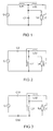
- the ignition devices shown schematically in FIGS. 1 to 9 serve to pressurize the auxiliary ignition electrode Z or Z 'of the high-pressure discharge lamp Lp with the ignition voltage required for this purpose.
- the ignition devices are each fed by an AC voltage source Q or Q ', which generates, for example, a sinusoidal or rectangular supply voltage or a sinusoidal or rectangular supply current.
- the embodiment of the ignition device according to the invention schematically illustrated in Figure 1 consists of an autotransformer L11, L12 and a capacitor C1.
- the autotransformer has a winding having a first winding portion L11 formed as a primary winding and a second winding portion L12, which is designed as a secondary winding of the transformer.
- the capacitor C1 and the primary winding section L11 are connected as a series resonant circuit connected to the AC power source Q.
- the resonant frequency of the series resonant circuit is preferably selected above 300 kHz, in particular above 1 MHz, which results in a small size and a particularly low required voltage at the auxiliary ignition electrode.
- the frequency of the supply voltage or the supply current is selected during the ignition phase near the resonance frequency of the series resonant circuit or selected such that a harmonic of the supply signal leads to an excitation of the series resonant circuit during the ignition phase.
- the center tap between the two winding sections L11, L12, which is formed as a common first terminal of the winding sections L11, L12, is connected both to the first electrode of the high-pressure discharge lamp Lp and to one terminal of the capacitor C1.
- the second terminal of the primary winding section L11 is connected to the AC voltage source Q, while the second terminal of the secondary winding section L12 is connected to the auxiliary starting electrode Z of the high-pressure discharge lamp Lp.
- the capacitor C1 is connected in parallel with the discharge path of the lamp Lp.
- the lamp Lp is, for example, a mercury-free metal halide high-pressure discharge lamp, which is provided as a light source in a vehicle headlight.
- the Entladwigsgefäß this high-pressure discharge lamp Lp consists either of a translucent ceramic, such as alumina ceramic, or quartz glass.
- the auxiliary starting electrode Z is applied for example as an electrically conductive coating on the outside of the discharge vessel or as a wire, so that a capacitive coupling between the Zündangeselektrode Z and at least one of the two disposed within the discharge vessel electrodes of the high pressure discharge lamp Lp.
- the resonance capacitor C1 has a capacitance of 94 pF (measured at a frequency of 1 kHz).
- the primary winding section L11 has 70 turns and an inductance of 100 ⁇ H (measured at a frequency of 1 kHz).
- the secondary winding section L12 has 95 turns.
- an AC voltage source Q which has a nearly sinusoidal AC voltage with an effective value of 90 V and a frequency of 1.248 MHz, which corresponds to the empirically determined resonant frequency of the resonant circuit formed from the components used.
- the AC voltage source Q is a voltage converter, for example a push-pull converter, which generates the desired AC voltage from the vehicle electrical system voltage of the motor vehicle.
- the frequency of the AC voltage provided by the AC source Q is tuned to the resonant frequency of the series resonant circuit C1, L11, so that builds up on the components C1 and L11 a resonance-elevated AC voltage with a peak value of more than 1000 volts.
- This voltage is also applied to the discharge path between the two electrodes of the high-pressure gas discharge lamp Lp, since the resonance capacitor C1 is connected in parallel to the discharge path of the lamp Lp.
- the resonance-boosted AC voltage is transformed up to a peak value of 2500 volts and fed to the auxiliary starting electrode Z.
- the ignition device After ignition of the gas discharge in the high-pressure discharge lamp Lp, the ignition device is automatically deactivated, since the high-pressure discharge lamp then strongly attenuates the resonant circuit.
- the frequency of the AC voltage generated by the AC voltage source Q is increased so far that sets the desired lamp power.
- the primary winding section L11 is used for stabilizing the discharge, that is, limiting the lamp current.
- an alternating voltage source Q For operating the abovementioned high-pressure discharge lamp Lp with a discharge vessel made of quartz glass, an alternating voltage source Q is used, which has a nearly sinusoidal alternating voltage with an effective value of 195 V and a Has a frequency of 1.234 MHz.
- the frequency of the AC voltage provided by the AC voltage source Q is tuned to the resonant frequency of the series resonant circuit C1, L11, so that builds up on the components C1 and L11 a resonance-elevated AC voltage with a peak value of 1500 volts.
- This voltage is also applied to the discharge path between the two electrodes of the high-pressure gas discharge lamp Lp, since the resonance capacitor C1 is connected in parallel to the discharge path of the lamp Lp.
- the ignition assisting electrode Z is supplied with an alternating voltage having a peak value of 4000 volts. There is therefore a voltage difference of 4000 volts between the auxiliary starting electrode Z and the electrode of the high-pressure discharge lamp Lp connected to the AC voltage source Q and one terminal of the resonance capacitor C1, which is sufficient together with the voltage difference between the electrodes for igniting the gas discharge in the lamp Lp.
- the ignition device After ignition of the gas discharge in the Hochlichentladungsiampe Lp the ignition device is automatically deactivated because the high-pressure discharge lamp then strongly attenuates the resonant circuit.
- the frequency of the AC voltage generated by the AC voltage source Q is increased so far that sets the desired lamp power.
- the primary winding section L11 is used for stabilizing the discharge, that is, limiting the lamp current.
- a frequency modulation of the alternating voltage can be carried out during the ignition phase.
- a frequency sweep of 50 kHz and a sinusoidal modulation signal of 500 Hz are suitable for this purpose.
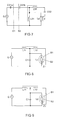
- the ignition device consists of an autotransformer L21, L22 and a capacitor C2.
- the autotransformer has a winding having a first winding portion L21 formed as a primary winding and a second winding portion L22 formed as a secondary winding of the transformer.
- the capacitor C2 and the primary winding section L21 are connected as a series resonant circuit which is connected to the AC voltage source Q.
- the center tap between the two winding sections L21, L22, which is formed as a common first terminal of the winding sections L21, L22, is connected both to the first electrode of the high-pressure discharge lamp Lp and to one terminal of the capacitor C2.
- the second terminal of the primary winding section L21 is connected to the AC power source Q and to the second electrode of the high pressure discharge lamp, while the second terminal of the secondary winding section L22 is connected to the auxiliary starting electrode Z of the high pressure discharge lamp Lp.
- the primary winding section L21 and not the resonance capacitor C2 are connected in parallel to the discharge path of the high-pressure discharge lamp Lp.
- the winding sections L21, L22 and the resonance capacitor C2 have the same dimension as the corresponding components L11, L12 and C1 of the first embodiment.
- the AC power source Q and the lamp Lp are also the same as the first embodiment.
- the capacitor C2 also prevents a DC flow through the lamp Lp.
- the resonance capacitor C2 has a capacity of 94 pF.
- the primary winding section L21 has 70 turns and an inductance of 100 ⁇ H.
- the secondary winding section L22 has 95 turns.
- the frequency of the AC voltage generated by the AC voltage source Q is linearly increased from 1.2 MHz to 1.3 MHz within 1 millisecond and then reduced again within the same time to 1.2 MHz to ensure in that the resonant frequency of the series resonant circuit C2, L21 lying in this frequency range is hit sufficiently well. This procedure is repeated until the gas discharge in the lamp Lp has ignited or a predetermined maximum period of time, For example, 100 ms, is exceeded and the AC voltage source Q is turned off. After the ignition of the gas discharge in the lamp Lp, the frequency of the alternating voltage is increased until the desired lamp power is established.
- a third embodiment of the ignition device according to the invention is shown.
- the third embodiment is largely consistent with the ignition device according to the second embodiment.
- the resonance capacity of the series resonant circuit of the ignition device is formed by two capacitors C31 and C32.
- the two resonance capacitors C31, C32 are connected in such a way that a complete potential separation between the AC voltage source Q and the components of the ignition device and the lamp Lp is ensured.
- the capacitor C31 has a capacitance of 235 pF and the capacitor C32 has a capacitance of 157 pF.
- the dimensioning and arrangement of the components L31, L32, Q, Lp and Z coincides with the dimensioning and arrangement of the components L21, L22, Q, Lp and Z of the second embodiment (see Figure 2).
- the operation also corresponds to that of the second embodiment.
- the illustrated in Figure 4 fourth embodiment of the ignition device according to the invention differs from the first embodiment only by the additional DC voltage isolation capacitor C42, which is connected between the high voltage output of the secondary winding section L42 and the auxiliary ignition Z of the high pressure discharge lamp Lp.
- the primary winding section L41 of the auto-transformer L41, L42 and the capacitor C41 form a series resonant circuit connected to the AC power source Q.
- the resonance capacitor C41 is connected in parallel with the discharge path of the high-pressure discharge lamp Lp.
- the center tap between the primary L41 and the secondary winding section L42 is connected to the capacitor C41 and to the first electrode of the high pressure discharge lamp Lp.
- the other terminal of the secondary winding section L42 is connected to the auxiliary starting electrode via the capacitor C42 Z connected.
- the second electrode of the lamp Lp is connected to the capacitor C41 and to the AC voltage source Q.
- the capacitor C42 prevents a direct current flow between the auxiliary starting electrode and the first and second electrodes of the high pressure discharge lamp Lp.
- the capacitance of the capacitor C42 can be freely selected within wide limits, without exerting a significant influence on the ignition process.
- the capacitor C42 is dimensioned such that the voltage drop across the capacitor C42 during the ignition process is smaller than the voltages that occur between the auxiliary starting electrode Z and the two electrodes of the high-pressure discharge lamp Lp. Therefore, very small capacitance values are sufficient for the capacitor C42, for example 33 pF. But also significantly larger values for the capacitance of the capacitor C42 such as 10 nF are possible.
- the operation of this embodiment corresponds to that of the first embodiment.
- the illustrated in Figure 5 fifth embodiment corresponds substantially to the illustrated in Figure 2 second embodiment of the invention. It differs from the second embodiment only by the additional DC voltage isolation capacitor C52, which is connected between the Zünclangesektrode Z and the high voltage terminal of the secondary winding section L52.
- the capacitor C5 1 and the primary winding portion L5 1 of the autotransformer L51, L52 form a series resonant circuit which is connected to the AC voltage source Q.
- the primary winding section L51 is connected in parallel to the discharge path of the high-pressure discharge lamp Lp.
- the arrangement and dimensioning of the components L51, L52, C51, Q, Lp and Z corresponds to the arrangement and dimensioning of the components L21, L22, C2, Q, Lp and Z of the second embodiment ( Figure 2) of the invention.
- the operation also corresponds to that of the second embodiment of the invention.
- FIG 6 the spatial distribution of the components of the ignition device according to the fifth embodiment ( Figure 5) is shown schematically.
- the components C51, L51, L52 and C52 of the igniter are housed in the lamp cap of the high pressure discharge lamp Lp.
- the electrical connections S2 of High-pressure discharge lamp Lp or the ignition device are connected by means of cables to the electrical terminals S1 of the AC voltage source Q.
- FIG. 7 schematically shows an alternative spatial distribution of the resonant capacitance of the series resonant circuit of the ignition device according to the invention.
- the resonant capacitance here consists of the two series-connected capacitors C51a and C51b.
- the capacitors C51a, C51b and the primary winding portion L51 of the autotransformer L51, L52 form a series resonant circuit connected to the AC power source Q here.
- the capacitors C51a, C51b here replace the capacitor C51 according to the fifth embodiment shown in FIGS. 5 and 6.
- the capacitor C51a is formed as a component of the AC voltage source or the ballast Q of the lamp Lp, while the capacitor C51b formed as part of the ignition device is housed together with the other components of the ignition device in the lamp base of the lamp Lp.
- the embodiment illustrated in Figure 7 corresponds to the fifth embodiment shown in Figures 5 and 6. For identical components, therefore, the same reference numerals have been used in Figures 5, 6 and 7.
- FIGS. 8 and 9 again show the ignition device according to the first exemplary embodiment of the invention and with the high-pressure discharge lamp Lp.
- the lamp Lp is here, however, provided with differently designed Zündangeselektroden Z1, or Z2. Therefore, the same reference numerals have been used in Figures 1, 8 and 9 for identical components.
- the auxiliary starting electrode Z1 is designed as a wire which protrudes into the interior of the outer bulb B 1 and bears against the outside of the discharge gap B2.
- the Zündisdraht Z1 is capacitively coupled to one of the electrodes disposed within the discharge vessel B2 of the high pressure discharge lamp Lp and led out of the Außcnkolben B 1 via a seal, such as a pinch seal and contacted with the high voltage terminal of the secondary winding section L 12.
- the auxiliary starting electrode Z1 consists essentially of a spring plate, which is arranged in the interior of the outer bulb B1 and capacitively coupled to one of the electrodes arranged inside the discharge vessel B2.
- the spring plate is contacted with a metallic layer on the inside of the outer bulb B2, which in turn is capacitively coupled to a second coating on the outside of the outer bulb B1.
- the two metallic coatings on the inside and outside of the outer bulb B1 face each other and form a capacitor in which the material or glass of the outer bulb forms the dielectric. This capacitor corresponds to the DC voltage isolation capacitor C52.
- the metallic coating on the outside of the outer bulb B1 is connected to the high voltage terminal of the secondary winding portion L12.
Landscapes
- Circuit Arrangements For Discharge Lamps (AREA)
- Discharge Lamps And Accessories Thereof (AREA)
- Discharge-Lamp Control Circuits And Pulse- Feed Circuits (AREA)
Abstract
Description
- Die Erfindung betrifft eine Zündvorrichtung gemäß dem Oberbegriff des Patentanspruchs 1 und eine Hochdruckentladungslampe mit einer derartigen Zündvorrichtung sowie ein Betriebsverfahren für eine Hochdruckentladungslampe.
- Die EP-A 0 294 604 beschreibt eine Schaltungsanordnung zum Betreiben einer Fahrzeugscheinwerfer-Hochdruckenttadungslampe mit einer sinusförmigen Wechselspannung. Die Schaltungsanordnung umfasst einen Serienresonanzkreis, der zum Zünden der Gasentladung in der Hochdruckentladungslampe am Resonanzkondensator mittels der Methode der Resonanzüberhöhung eine sinusförmige Wechselspannung mit einer Frequenz von 45 Kilohertz und einer Amplitude von bis zu 18000 Volt generiert, welche die Lampe innerhalb einer Zeitspanne von 6 Millisekunden zündet.
- Es ist Aufgabe der Erfindung, eine Zündvorrichtung für eine mit einer Zündhilfselektrode versehene Hochdruckentladungslampe bereitzustellen, die für den Betrieb der Hochdruckentladungslampe mit einem hochfrequenten Wechselstrom geeignet ist und einen im Vergleich zum Stand der Technik einfacheren Aufbau besitzt.
- Diese Aufgabe wird erfindungsgemäß durch die Merkmale des Patentanspruchs 1 gelöst. Besonders vorteilhafte Ausführungen der Erfindung sind in den abhängigen Patentansprüchen beschrieben.
- Die erfindungsgemäße Zündvorrichtung für eine mit einer Zündhilfselektrode versehene Hochdruckentladungslampe weist einen Serienresonanzkreis zum Erzeugen der Zündspannung für die Hochdruckentladungslampe auf, dessen Resonanzinduktivität die Primärwicklung eines Transformators umfasst, wobei die Sekundärwicklung dieses Transformators zum Beaufschlagen der Zündhilfselektrode der Hochdruckentladungslampe mit der Zündspannung vorgesehen ist. Dadurch kann für Wechselspannungen hoher Frequenzen, insbesondere für Frequenzen im Megahertzbereich, in der Primärwicklung des Transformators während der Zündphase der Hochdruckentladungslampe auf einfache Weise eine im Vergleich zur Versorgungsspannung der Zündvorrichtung resonanzüberhöhte Spannung generiert werden, die mittels der Sekundärwicklung des Transformators in die erforderliche Zündspannung der Lampe hochtransformiert und der Zündhilfselektrode der Hochdruckentladungslampe zugeführt wird. Zum Deaktivieren der Zündvorrichtung nach erfolgreicher Zündung der Gasentladung in der Hochdruckenttadungslampe genügt es, die Frequenz der Versorgungsspannung für die Zündvorrichtung und die Hochdruckentladungslampe derart zu ändern, dass ein ausreichender Frequenzabstand zu der Resonanzfrequenz des vorgenannten Serienresonanzkreises besteht. Dementsprechend besitzt die erfindungsgemäße Zündvorrichtung einen einfachen Aufbau. Ferner wird die Sekundärwicklung des Transformators während des Lampenbetriebs nicht von dem hochfrequenten Lampenstrom durchflossen, so dass keine nennenswerten Leistungsverluste in der Sekundärwicklung auftreten können. Außerdem ermöglicht die erfindungsgemäße Zündvorrichtung eine vollständige galvanische Trennung zwischen der Zündvorrichtung und ihrer Spannungsversorgungsschaltung bzw. der Betriebsschaltung der Hochdruckentladungslampe.
- Um die vorgenannte galvanische Trennung herbeizuführen, wird die Resonanzkapazität des Serienresonanzkreises vorteilhafter Weise von mindestens zwei Kondensatoren gebildet, die derart geschaltet sind, dass sie einen Gleichstromfluss zwischen der Spannungsversorgungsschaltung und den Komponenten der Zündvorrichtung verhindern.
- Vorteilhafterweise ist gemäß einiger bevorzugter Ausführungsbeispiele der Erfindung auch ein Gleichspannungstrennkondensator vorgesehen. um den Natriumverlust im Entladungsplasma bedingt durch die Diffusion von Natriumionen zur Entladungsgefäßwand zu reduzieren. Die Kapazität des Gleichspannungstrennkondensators wird dabei so dimensioniert, dass einerseits die Zündhilfselektrode mit einer ausreichend hohen Spannung zum Zünden der Gasentladung beaufschlagt wird und andererseits die vorgenannte Natriumdiffusion in hinreichendem Maß reduziert wird. Bei zu großer Kapazität oder zu hohem Leckstrom des Gleichspannungstrennkondensators wird keine ausreichende Reduktion der Natriumdiffusion erreicht und bei zu kleiner Kapazität kann die Zündhilfselektrode nicht mit ausreichend hoher Spannung zum Zünden der Gasentladung beaufschlagt werden.
- Der Transformator der erfindungsgemäßen Zündvorrichtung ist vorteilhafter Weise als Spartransformator ausgebildet, das heißt, der Transformator besitzt nur eine einzige Wicklung mit einem ersten Wicklungsabschnitt, der als Primärwicklung ausgebildet ist, und einem zweiten Wicklungsabschnitt, der als Sekundärwicklung ausgebildet ist, wobei ein Anschluss dieser Wicklungsabschnitte als gemeinsamer Anschluss ausgebildet ist. Dadurch kann eine platzsparende Anordnung des Transformators und der Zündvorrichtung gewährleistet werden, so class die komplette Zündvorrichtung in den Lampensockel der Hochdruckentladungslampe integrierbar ist. Außerdem ist die Wicklung bzw. sind die Wicklungen des Transformators der erfindungsgemäßen Zündvorrichtung vorzugsweise als gerichtete Lagenwicklung bzw. Lagenwicklungen in Kammer- oder Kreuzwicklung ausgebildet, um eine möglichst hohe Eigenresonanzfrequenz des Transformators zu gewährleisten.
- Das erfindungsgemäße Betriebsverfahren für eine Hochdruckentladungslampe zeichnet sich dadurch aus, Class eine resonanzüberhöhte Wechselspannung zum Zünden der Gasentladung in dem Entladungsgefaß der Hochdruckentladungslampe bereitgestellt wird, wobei die resonanzüberhöhte Wechselspannung mit Hilfe eines Transformators generiert wird und in eine höhere Spannung transformiert wird, die einer Zündhilfselektrode der Hochdruckentladungslampe zugeführt wird. Dadurch kann mit wesentlich geringerem Aufwand die erforderliche Zündspannung für die Hochdruckentladungslampe erzeugt werden, weil im Unterschied zum Stand der Technik nun die durch die Methode der Resonanzüberhöhung bereitzustellende Spannung nur noch ein Bruchteil der erforderlichen Hochspannung an der Zündhilfselektrode ist. Vorzugsweise wird die resonanzüberhöhte Wechselspannung mittels der Primärwicklung des Transformators generiert, die als Bestandteil eines Serienresonanzkreises ausgebildet ist, und die der Zündhilfselektrode zugeführte höhere Spannung wird mit Hilfe der Sekundärwicklung des Transformators erzeugt. Außerdem wird zum Bereitstellen der resonanzüberhöhten Wechselspannung vorzugsweise eine Frequenzmodulation der von der Spannungsquelle generierten Versorgungsspannung durchgeführt, um Änderungen der Resonanzfrequenz des oben genannten Serienresonanzkreises bedingt durch Bauteiletoleranzen, Temperaturschwankungen und Alterung der Bauteile zu berücksichtigen.
- Nach erfolgter Zündung der Gasentladung in der Hochdruckentladungslampe wird vorteilhafter Weise eine in Serie zur Entladungsstrecke der Hochdruckentladungslampe geschaltete Impedanz, beispielsweise die Primärwicklung des vorgenannten Transformators, zur Stabilisierung der Gasentladung verwendet. Der vorgenannte Serienresonanzkreis kann nach erfolgter Zündung der Gasentladung in der Hochdruckentladungslampe vorteilhafter Weise auch benutzt werden, um durch Änderung der Frequenz der Versorgungsspannung der Hochdruckentladungslampe ihre elektrische Leistungsaufnahme auf den gewünschten Wert einzustellen.
- Nachstehend wird die Erfindung anhand mehrerer bevorzugter Ausführungsbeispiele näher erläutert. Es zeigen:
- Figur 1
- Eine Schaltskizze der Zündvorrichtung gemäß dem ersten Ausführungsbeispiel der Erfindung
- Figur 2
- Eine Schaltskizze der Zündvorrichtung gemäß dem zweiten Ausführungsbeispiel der Erfindung
- Figur 3
- Eine Schaltskizze der Zündvorrichtung gemäß dem dritten Ausführungsbeispiel der Erfindung
- Figur 4
- Eine Schaltskizze der Zündvorrichtung gemäß dem vierten Ausführungsbeispiel der Erfindung
- Figur 5
- Eine Schaltskizze der Zündvorrichtung gemäß dem fünften Ausführungsbeispiel der Erfindung
- Figur 6
- Eine Schaltskizze der Zündvorrichtung gemäß dem fünften Ausführungsbeispiel der Erfindung mit einer Zuordnung der Komponenten zum Lampensockel
- Figur 7
- Eine Schaltskizze der Zündvorrichtung gemäß dem sechsten Ausführungsbeispiel der Erfindung
- Figur 8
- Eine Schaltskizze der Zündvorrichtung gemäß dem ersten Ausführungsbeispiel der Erfindung mit einer Zündhilfselektrode gemäß einer ersten Ausführungsform
- Figur 9
- Eine Schaltskizze der Zündvorrichtung gemäß dem ersten Ausführungsbeispiel der Erfindung mit einer Zündhilfselektrode gemäß einer zweiten Ausführungsform
- Die in den Figuren 1 bis 9 schematisch dargestellten Zündvorrichtungen dienen zum Beaufschlagen der Zündhilfselektrode Z bzw. Z' der Hochdruckendadungslampe Lp mit der dafür erforderlichen Zündspannung. Die Zündvorrichtungen werden jeweils von einer Wechselspannungsquelle Q bzw. Q' gespeist, die beispielsweise eine sinusförmige oder rechteckförmige Versorgungsspannung bzw. einen sinusförmigen oder rechteckförmigen Versorgungsstrom generiert.
- Das in Figur 1 schematisch dargestellte Ausführungsbeispiel der erfindungsgemäßen Zündvorrichtung besteht aus einem Spartransformator L11, L12 und einem Kondensator C1. Der Spartransformator besitzt eine Wicklung mit einem ersten Wicklungsabschnitt L11, der als Primärwicklung ausgebildet ist, und mit einem zweiten Wicklungsabschnitt L12, der als Sekundärwicklung des Transformators ausgebildet ist. Der Kondensator C1 und der Primärwicklungsabschnitt L11 sind als Serienresonanzkreis geschaltet, der an die Wechselspannungsquelle Q angeschlossen ist. Die Resonanzfrequenz des Serienresonanzkreises wird vorzugsweise oberhalb 300 kHz, insbesondere oberhalb von 1 MHz gewählt, was in einer kleinen Baugröße und einer besonders geringen erforderlichen Spannung an der Zündhilfselektrode resultiert. Die Frequenz der Versorgungsspannung bzw. des Versorgungsstroms wird während der Zündphase nahe der Resonanzfrequenz des Serienresonanzkreises gewählt bzw. derart gewählt, dass eine Oberschwingung des Versorgungssignals zu einer Anregung des Serienresonanzkreises während der Zündphase führt.
- Der Mittenabgriff zwischen den beiden Wicklungsabschnitten L11, L12, der als gemeinsamer erster Anschluss der Wicklungsabschnitte L11, L12 ausgebildet ist, ist sowohl mit der ersten Elektrode der Hochdruckentladungslampe Lp als auch mit einem Anschluss des Kondensators C1 verbunden. Der zweite Anschluss des Primärwicklungsabschnitts L11 ist mit der Wechselspannungsquelle Q verbunden, während der zweite Anschluss des Sekundärwicklungsabschnitts L12 mit der Zündhilfselektrode Z der Hochdruckentladungslampe Lp verbunden ist. Der Kondensator C1 ist parallel zur Entladungsstrecke der Lampe Lp geschaltet. Bei der Lampe Lp handelt es sich beispielsweise um eine quecksilberfreie Halogen-Metalldampf-Hochdruckentladungslampe, die als Lichtquelle in einem Fahrzeugscheinwerfer vorgesehen ist. Das Entladwigsgefäß dieser Hochdruckentladungslampe Lp besteht entweder aus einer lichtdurchlässigen Keramik, beispielsweise aus Aluminiumoxidkeramik, oder aus Quarzglas. Die Zündhilfselektrode Z ist beispielsweise als elektrisch leitfähige Beschichtung auf der Außenseite des Entladungsgefäßes aufgebracht oder als Draht ausgebildet, so dass eine kapazitive Kopplung zwischen der Zündhilfselektrode Z und mindestens einer der beiden innerhalb des Entladungsgefäßes angeordneten Elektroden der Hochdruckentladungslampe Lp besteht. Der Resonanzkondensator C1 besitzt eine Kapazität von 94 pF (bei einer Frequenz von 1 kHz gemessen). Der Primärwicklungsabschnitt L11 besitzt 70 Windungen und eine Induktivität von 100 µH (bei einer Frequenz von 1 kHz gemessen). Der Sekundärwicklungsabschnitt L12 besitzt 95 Windungen.
- Zum Betreiben der vorgenannten Hochdruckentladungslampe mit keramischen Entladungsgefäß wird eine Wechselspannungsquelle Q verwendet, die eine nahezu sinusförmige Wechselspannung mit einem Effektivwert von 90 V und einer Frequenz von 1,248 MHz besitzt, die der empirisch ermittelten Resonanzfrequenz des aus den verwendeten Bauelementen gebildeten Resonanzkreises entspricht. Bei der Wechselspannungsquelle Q handelt es sich um einen Spannungswandler, beispielsweise einen Gegentaktwandler, der aus der Bordnetzspannung des Kraftfahrzeugs die gewünschte Wechselspannung generiert. Zum Zünden der Gasentladung in der Hochdruckentladungslampe Lp wird die Frequenz der von der Wechselspannungsquelle Q bereitgestellten Wechselspannung auf die Resonanzfrequenz des Serienresonanzkreises C1, L11 abgestimmt, so dass sich an den Bauteilen C1 und L11 eine resonanzüberhöhte Wechselspannung mit einem Spitzenwert von mehr als 1000 Volt aufbaut. Diese Spannung liegt auch an der Entladungsstrecke zwischen den beiden Elektroden der Hochdruckgasentladungslampe Lp an, da der Resonanzkondensator C1 parallel zur Entladungsstrecke der Lampe Lp geschaltet ist. Mittels des Sekundärwicklungsabschnitts L12 wird die resonanzüberhöhte Wechselspannung auf einen Spitzenwert von 2500 Volt hochtransformiert und der Zündhilfselektrode Z zugeführt. Zwischen der Zündhilfselektrode Z und der mit der Wechselspannungsquelle Q und einem Anschluss des Resonanzkondensators C1 verbundenen Elektrode der Hochdruckentladungslampe Lp besteht daher eine Spannungsdifferenz von 2500 Volt, die zum Zünden der Gasentladung in der Lampe Lp ausreicht. Nach erfolgter Zündung der Gasentladung in der Hochdruckentladungslampe Lp wird die Zündvorrichtung automatisch deaktiviert, da die Hochdruckentladungslampe dann den Resonanzkreis stark bedämpft. Die Frequenz der von der Wechselspannungsquelle Q generierten Wechselspannung wird so weit erhöht, dass sich die gewünschte Lampenleistung einstellt. Während des Betriebs der Hochdruckentladungslampe Lp wird der Primärwicklungsabschnitt L11 zur Stabilisierung der Entladung, das heißt, zur Begrenzung des Lampenstroms, benutzt.
- Zum Betreiben der oben genannten Hochdruckentladungslampe Lp mit einem Entladungsgefäß aus Quarzglas wird eine Wechselspannungsquelle Q verwendet, die eine nahezu sinusförmige Wechselspannung mit einem Effektivwert von 195 V und einer Frequenz von 1,234 MHz besitzt. Zum Zünden der Gasentladung in der Hochdruckentladungslampe Lp wird die Frequenz der von der Wechselspannungsquelle Q bereitgestellten Wechselspannung auf die Resonanzfrequenz des Serienresonanzkreises C1, L11 abgestimmt, so dass sich an den Bauteilen C1 und L11 eine resonanzüberhöhte Wechselspannung mit einem Spitzenwert von 1500 Volt aufbaut. Diese Spannung liegt auch an der Entladungsstrecke zwischen den beiden Elektroden der Hochdruckgasentladungslampe Lp an, da der Resonanzkondensator C1 parallel zur Entladungsstrecke der Lampe Lp geschaltet ist. Mittels des Sekundärmicklungsabschnitts L12 wird der Zündhilfselektrode Z eine Wechselspannung mit einem Spitzenwert von 4000 Volt zugeführt. Zwischen der Zündhilfselektrode Z und der mit der Wechselspannungsquelle Q und einem Anschluss des Resonanzkondensators C1 verbundenen Elektrode der Hochdruckentladungslampe Lp besteht daher eine Spannungsdifferenz von 4000 Volt, die zusammen mit der Spannungsdifferenz zwischen den Elektroden zum Zünden der Gasentladung in der Lampe Lp ausreicht. Nach erfolgter Zündung der Gasentladung in der Hochdruckentladungsiampe Lp wird die Zündvorrichtung automatisch deaktiviert, da die Hochdruckentladungslampe dann den Resonanzkreis stark bedämpft. Die Frequenz der von der Wechselspannungsquelle Q generierten Wechselspannung wird so weit erhöht, dass sich die gewünschte Lampenleistung einstellt. Während des Betriebs der Hochdruckentladungslampe Lp wird der Primärwicklungsabschnitt L11 zur Stabilisierung der Entladung, das heißt, zur Begrenzung des Lampenstroms, benutzt.
- Um zu gewährleisten, dass die Frequenz der von der Wechselspannungsquelle generierten Wechselspannung während der Zündphase ausreichend nahe bei der Resonanzfrequenz des wegen seiner hohen Güte sehr schmalbandigen Serienresonanzkreises liegt, kann während der Zündphase eine Frequenzmodulation der Wechselspannung durchgeführt werden. Hierfür eignen sich beispielsweise bei einer Mittenfrequenz von 1,23 MHz ein Frequenzhub von 50 kHz und ein sinusförmiges Modulationssignal mit 500 Hz.
- Bei dem in Figur 2 abgebildeten zweiten Ausführungsbeispiel der erfindungsgemäßen Zündvorrichtung besteht die Zündvorrichtung aus einem Spartransformator L21, L22 und einem Kondensator C2. Der Spartransformator besitzt eine Wicklung mit einem ersten Wicklungsabschnitt L21, der als Primärwicklung ausgebildet ist, und mit einem zweiten Wicklungsabschnitt L22, der als Sekundärwicklung des Transformators ausgebildet ist. Der Kondensator C2 und der Primärwicklungsabschnitt L21 sind als Serienresonanzkreis geschaltet, der an die Wechselspannungsquelle Q angeschlossen ist. Der Mittenabgriff zwischen den beiden Wicklungsabschnitten L21, L22, der als gemeinsamer erster Anschluss der Wicklungsabschnitte L21, L22 ausgebildet ist, ist sowohl mit der ersten Elektrode der Hochdruckentladungslampe Lp als auch mit einem Anschluss des Kondensators C2 verbunden. Der zweite Anschluss des Primärwicklungsabschnitts L21 ist mit der Wechselspannungsquelle Q und mit der zweiten Elektrode der Hochdruckentladungslampe verbunden, während der zweite Anschluss des Sekundärwicklungsabschnitts L22 mit der Zündhilfselektrode Z der Hochdruckentladungslampe Lp verbunden ist. Im Unterschied zu dem ersten Ausführungsbeispiel (Figur 1) ist bei dem zweiten Ausführungsbeispiel der Primärwicklungsabschnitt L21 und nicht der Resonanzkondensator C2 parallel zur Entladungsstrecke der Hochdruckentladungslampe Lp geschaltet. Die Wicklungsabschnitte L21, L22 und der Resonanzkondensator C2 besitzen die gleiche Dimensionierung wie die entsprechenden Komponenten L11, L12 und C1 des ersten Ausführungsbeispiels. Die Wechselspannungsquelle Q und die Lampe Lp stimmen ebenfalls mit dem ersten Ausführungsbeispiel überein. Der Kondensator C2 verhindert auch einen Gleichstromfluss durch die Lampe Lp. Der Resonanzkondensator C2 besitzt eine Kapazität von 94 pF. Der Primärwicklungsabschnitt L21 besitzt 70 Windungen und eine Induktivität von 100 µH. Der Sekundärwicklungsabschnitt L22 besitzt 95 Windungen.
- Zum Zünden der Gasentladung in der Lampe Lp wird die Frequenz der von der Wechselspannungsquelle Q generierten Wechselspannung linear von 1,2 MHz bis 1,3 MHz innerhalb von 1 Millisekunde erhöht und anschließend wieder innerhalb derselben Zeitspanne auf 1,2 MHz reduziert, um zu gewährleisten, dass die in diesem Frequenzbereich liegende Resonanzfrequenz des Serienresonanzkreises C2, L21 ausreichend gut getroffen wird. Diese Prozedur wird solange wiederholt, bis die Gasentladung in der Lampe Lp gezündet hat oder eine vorgegebene maximale Zeitspanne, beispielsweise 100 ms, überschritten ist und die Wechselspannungsquelle Q abgeschaltet wird. Nach der Zündung der Gasentladung in der Lampe Lp wird die Frequenz der Wechselspannung erhöht bis sich die gewünschte Lampenleistung einstellt.
- In Figur.3 ist ein drittes Ausführungsbeispiel der erfindungsgemäßen Zündvorrichtung dargestellt. Das dritte Ausführungsbeispiel stimmt weitgehend mit der Zündvorrichtung gemäß dem zweiten Ausführungsbeispiel überein. Im Unterschied zum zweiten Ausführungsbeispiel wird beim dritten Ausführungsbeispiel der erfindungsgemäßen Zündvorrichtung die Resonanzkapazität des Serienresonanzkreises der Zündvorrichtung von zwei Kondensatoren C31 und C32 gebildet. Die beiden Resonanzkondensatoren C31, C32 sind derart geschaltet, dass eine vollständige Potentialtrennung zwischen der Wechselspannungsquelle Q und den Komponenten der Zündvorrichtung sowie der Lampe Lp gewährleistet ist. Der Kondensator C31 besitzt eine Kapazität von 235 pF und der Kondensator C32 weist eine Kapazität von 157 pF auf. Die Dimensionierung und Anordnung der Bauteile L31, L32, Q, Lp und Z stimmt mit der Dimensionierung und Anordnung der Bauteile L21, L22, Q, Lp und Z des zweiten Ausführungsbeispiels (siehe Figur 2) überein. Die Betriebsweise entspricht ebenfalls der des zweiten Ausführungsbeispiels.
- Das in Figur 4 dargestellte vierte Ausführungsbeispiel der erfindungsgemäßen Zündvorrichtung unterscheidet sich von dem ersten Ausführungsbeispiel nur durch den zusätzlichen Gleichspannungstrennungskondensator C42, der zwischen dem Hochspannungsausgang des Sekundärwicklungsabschnitts L42 und der Zündhilfselektrode Z der Hochdruckentladungslampe Lp geschaltet ist. Der Primärwicklungsabschnitt L41 des Spartransformators L41, L42 und der Kondensator C41 bilden einen Serienresonanzkreis, der an die Wechselspannungsquelle Q angeschlossen ist. Der Resonanzkondensator C41 ist parallel zur Entladungsstrecke der Hochdruckentladungslampe Lp geschaltet. Der Mittenabgriff zwischen dem Primär- L41 und dem Sekundärwicklungsabschnitt L42 ist an den Kondensator C41 und an die erste Elektrode der Hochdruckentladungslampe Lp angeschlossen. Der andere Anschluss des Sekundärwicklungsabschnitts L42 ist über den Kondensator C42 an die Zündhilfselektrode Z angeschlossen. Die zweite Elektrode der Lampe Lp ist an den Kondensator C41 und an die Wechselspannungsquelle Q angeschlossen. Der Kondensator C42 verhindert einen Gleichstromfluss zwischen der Zündhilfselektrode und der ersten sowie zweiten Elektrode der Hochdruckentladungslampe Lp. Die Kapazität des Kondensators C42 kann in weiten Grenzen frei gewählt werden, ohne einen nennenswerten Einfluss auf den Zündvorgang auszuüben. Vorzugsweise wird der Kondensator C42 so dimensioniert, dass der Spannungsabfall am Kondensator C42 während des Zündvorgangs kleiner als die sich zwischen der Zündhilfselektrode Z und den beiden Elektroden der Hochdruckentladungslampe Lp einstellenden Spannungen ist. Es genügen daher sehr kleine Kapazitätswerte für den Kondensator C42, beispielsweise 33 pF. Aber auch deutlich größere Werte für die Kapazität des Kondensators C42 wie etwa 10 nF sind möglich. Im übrigen entspricht die Betriebsweise dieses Ausführungsbeispiels der des ersten Ausführungsbeispiels.
- Das in Figur 5 dargestellte fünfte Ausführungsbeispiel entspricht im wesentlichen dem in Figur 2 abgebildeten zweiten Ausführungsbeispiel der Erfindung. Es unterscheidet sich vom zweiten Ausführungsbeispiel nur durch den zusätzlichen Gleichspannungstrennungskondensator C52, der zwischen der Zünclhilfselektrode Z und dem Hochspannungsanschluss des Sekundärwicklungsabschnitts L52 geschaltet ist. Der Kondensator C5 1 und der Primärwicklungsabschnitt L5 1 des Spartransformators L51, L52 bilden einen Serienresonanzkreis, der an die Wechselspannungsquelle Q angeschlossen ist. Der Primärwicklungsabschnitt L51 ist parallel zur Entladungsstrecke der Hochdruckentladungslampe Lp geschaltet. Die Anordnung und Dimensionierung der Bauteile L51, L52, C51, Q, Lp und Z entspricht der Anordnung und Dimensionierung der Bauteile L21, L22, C2, Q, Lp und Z des zweiten Ausführungsbeispiels (Figur 2) der Erfindung. Die Betriebsweise entspricht ebenfalls der des zweiten Ausführungsbeispiels der Erfindung.
- In Figur 6 ist die räumliche Aufteilung der Komponenten der Zündvorrichtung gemäß dem fünften Ausführungsbeispiel (Figur 5) schematisch dargestellt. Die Komponenten C51, L51, L52 und C52 der Zündvorrichtung sind im Lampensockel der Hochdruckentladungslampe Lp untergebracht. Die elektrischen Anschlüsse S2 der Hochdruckentladungslampe Lp bzw. der Zündvorrichtung sind mittels Kabel mit den elektrischen Anschlüssen S1 der Wechselspannungsquelle Q verbunden.
- In Figur 7 ist eine alternative räumliche Aufteilung der Resonanzkapazität des Serienresonanzkreises der erfindungsgemäßen Zündvorrichtung schematisch dargestellt. Die Resonanzkapazität besteht hier aus den beiden in Serie geschalteten Kondensatoren C51a und C51b. Die Kondensatoren C51a, C51b und der Primärwicklungsabschnitt L51 des Spartransformators L51, L52 bilden hier einen Serienresonanzkreis, der an die Wechselspannungsquelle Q angeschlossen ist. Die Kondensatoren C51a, C51 b ersetzen hier den Kondensator C51 gemäß dem in den Figuren 5 und 6 dargestellten fünften Ausführungsbeispiel. Der Kondensator C51a ist als Bestandteil der Wechselspannungsquelle bzw. des Vorschaltgerätes Q der Lampe Lp ausgebildet, während der Kondensator C51b als Bestandteil der Zündvorrichtung ausgebildet zusammen mit den anderen Komponenten der Zündvorrichtung in dem Lampensockel der Lampe Lp untergebracht ist. In allen anderen Details entspricht das in Figur 7 dargestellte Ausführungsbeispiel dem in den Figuren 5 und 6 abgebildeten fünften Ausführungsbeispiel. Für identische Bauteile wurden daher in den Figuren 5, 6 und 7 dieselben Bezugszeichen verwendet.
- In den Figuren 8 und 9 ist wieder die Zündvorrichtung gemäß dem ersten Ausführungsbeispiel der Erfindung und mit der Hochdruckentladungslampe Lp dargestellt. Die Lampe Lp ist hier allerdings mit unterschiedlich ausgeführten Zündhilfselektroden Z1, bzw. Z2 versehen. Daher wurden in den Figuren 1, 8 und 9 für identische Bauteile dieselben Bezugszeichen verwendet.
- Bei der in Figur 8 schematisch dargestellten Hochdruckentladungslampe Lp ist die Zündhilfselektrode Z1 als Draht ausgebildet, der in den Innenraum des Außenkolbens B 1 hineinragt und an der Außenseite des Entladungsgelaßes B2 anliegt. Der Zündhilfsdraht Z1 ist kapazitiv an eine der Elektroden der innerhalb des Entladungsgefäßes B2 der Hochdruckentladungslampe Lp angeordneten gekoppelt und über eine Dichtung, beispielsweise eine Quetschdichtung, aus dem Außcnkolben B 1 herausgeführt und mit dem Hochspannungsanschluss des Sekundärwicklungsabschnitts L 12 kontaktiert.
- Bei der in Figur 9 schematisch dargestellten Hochdruckentladungslampe Lp besteht die Zündhilfselektrode Z1 im wesentlichen aus einem Federblech, das im Innenraum des Außenkolbens B1 angeordnet und kapazitiv an eine der innerhalb des Entladungsgefäßes B2 angeordnete Elektrode gekoppelt ist. Das Federblech ist mit einer metallischen Schicht auf der Innenseite des Außenkolbens B2 kontaktiert, die wiederum kapazitiv an eine zweite Beschichtung auf der Außenseite des Außenkolbens B1 gekoppelt ist. Die beiden metallischen Beschichtungen auf der Innen- und Außenseite des Außenkolbens B1 liegen einander gegenüber und bilden einen Kondensator, bei dem das Material bzw. Glas des Außenkolbens das Dielektrikum bildet. Dieser Kondensator entspricht dem Gleichspannungstrennungskondensator C52. Die metallische Beschichtung auf der Außenseite des Außenkolbens B1 ist mit dem Hochspannungsanschluss des Sekundärwicklungsabschnitts L12 verbunden.
Claims (15)
- Zündvorrichtung für eine mit einer Zündhilfselektrode (Z) versehene Hochdruckentladungslampe (Lp), wobei die Zündvorrichtung einen Serienresonanzkreis zum Erzeugen der Zündspannung für die Hochdruckentladungslampe (Lp) aufweist, dadurch gekennzeichnet, dass die Resonanzindulctivität des Serienresonanzkreises die Primärwicklung (L11) eines Transformators umfasst, dessen Sekundärwicklung (L12) zum Beaufschlagen der Zündhilfselektrode (Z) der Hochdruckentladungslampe (Lp) mit der Zündspannung vorgesehen ist.
- Zündvorrichtung nach Anspruch 1, dadurch gekennzeichnet, dass der Transformator als Spartransformator (L11, L12) ausgebildet ist.
- Zündvorrichtung nach Anspruch 1 oder 2, dadurch gekennzeichnet, dass die Wicklung bzw. Wicklungen des Transformators als gerichtete Lagenwicklung bzw. Lagenwicklungen in Kammer- oder Kreuzwicklung ausgebildet ist bzw. sind.
- Zündvorrichtung nach Anspruch 1 oder 2, dadurch gekennzeichnet, dass die Resonanzkapazität des Serienresonanzkreises von mindestens zwei Kondensatoren (C31, C32) gebildet wird, die derart geschaltet sind, dass sie eine galvanische Trennung der Zündvorrichtung von ihrer Spannungsversorgungsschaltung (Q) bewirken.
- Zündvorrichtung nach Anspruch 1, dadurch gekennzeichnet, dass ein Gleichspannungstrennkondensator (C42) vorgesehen ist.
- Hochdruckentladungslampe (Lp) mit einer Zündhilfselektrode (Z), einem Lampensockel und einer im Innenraum des Lampensockels angeordneten Zündvorrichtung gemäß einem oder mehreren der Ansprüche I bis 5.
- Hochdruckentladungslampe nach Anspruch 6, wobei die Hochdruckentladungslampe (Lp) ein Entladungsgefäß (B2) mit zwei darin angeordneten Elektroden zum Erzeugen einer Gasentladung aufweist, dadurch gekennzeichnet, dass eine Primär- (L11) und Sekundärwicklung (L12) des Transformators an einem ihrer Anschlüsse miteinander elektrisch leitend verbunden sind und dieser gemeinsame, erste Anschluss mit einer Elektrode sowie einem Anschluss eines Kondensators (C1) der Resonanzkapazität verbunden ist, und der andere, zweite Anschluss der Sekundärwicklung (L12) an die Zündhilfselektrode (Z) gekoppelt ist.
- Hochdruckentladungslampe nach Anspruch 7, dadurch gekennzeichnet, dass der zweite Anschluss der Sekundärwicklung (L12) mit der Zündhilfselektrode (Z) elektrisch leitend verbunden ist.
- Hochdruckentladungslampe nach Anspruch 7, dadurch gekennzeichnet, dass der zweite Anschluss der Sekundärwicklung über einen Gleichspannungstrennungskondensator an die Zündhilfselektrode angeschlossen ist.
- Hochdruckentladungslampe nach Anspruch 9 mit einem das Entladungsgefäß (B2) umgebenden Außenkolben (B1), dadurch gekennzeichnet, dass der Gleichspannungstrennungskondensator von elektrisch leitfähigen Beschichtungen auf der Innen- und Außenseite des Außenkolbens (B1) gebildet wird, wobei das Material des Außenkolbens (B1) als Dielektrikum dient.
- Verfahren zum Betreiben einer Hochdruckentladungslampe, wobei eine resonanzüberhöhte Wechselspannung zum Zünden der Gasentladung in dem Entladungsgefäß der Hochdruckentladungslampe bereitgestellt wird, dadurch gekennzeichnet, dass die resonanzüberhöhte Wechselspannung mit Hilfe eines Transformators (L11, L12) generiert und in eine höhere Spannung transformiert wird, die einer Zündhilfselektrode (Z) der Hochdruckentladungslampe (Lp) zugeführt wird.
- Verfahren nach Anspruch 11, dadurch gekennzeichnet, dass die resonanzüberhöhte Wechselspannung mit Hilfe der Primärwicklung (L11) des Transformators, die als Bestandteil eines Serienresonanzkreises ausgebildet ist, generiert wird und die höhere Spannung mit Hilfe der Sekundärwicklung (L12) des Transformators erzeugt wird.
- Verfahren nach Anspruch 11 oder 12, dadurch gekennzeichnet, dass nach erfolgter Zündung der Gasentladung in der Hochdruckentladungslampe eine in Serie zur Entladungsstrecke der Hochdruckentladungslampe geschaltete Impedanz des Serienresonanzkreises zur Stabilisierung der Gasentladung verwendet wird.
- Verfahren nach Anspruch 13, dadurch gekennzeichnet, dass die gewünschte elektrische Leistungsaufnahme der Hochdruckentladungslampe durch Änderung der Frequenz ihrer Versorgungsspannung eingestellt wird.
- Verfahren nach Anspruch 11, dadurch gekennzeichnet, dass zum Bereitstellen der resonanzüberhöhten Wechselspannung eine Frequenzmodulation der von einer Spannungsquelle generierten Versorgungsspannung durchgeführt wird.
Applications Claiming Priority (1)
| Application Number | Priority Date | Filing Date | Title |
|---|---|---|---|
| DE102004052299A DE102004052299A1 (de) | 2004-10-27 | 2004-10-27 | Zündvorrichtung für eine Hochdruckentlandungslampe und Hochdruckentladungslampe mit Zündvorrichtung sowie Betriebsverfahren für eine Hochdruckentladungslampe |
Publications (2)
| Publication Number | Publication Date |
|---|---|
| EP1653785A1 true EP1653785A1 (de) | 2006-05-03 |
| EP1653785B1 EP1653785B1 (de) | 2009-07-29 |
Family
ID=35295411
Family Applications (1)
| Application Number | Title | Priority Date | Filing Date |
|---|---|---|---|
| EP05022448A Not-in-force EP1653785B1 (de) | 2004-10-27 | 2005-10-14 | Zündvorrichtung für eine Hochdruckentladungslampe und Hochdruckentladungslampe mit Zündvorrichtung sowie Betriebsverfahren für eine Hochdruckentladungslampe |
Country Status (7)
| Country | Link |
|---|---|
| US (1) | US7378800B2 (de) |
| EP (1) | EP1653785B1 (de) |
| JP (1) | JP4915642B2 (de) |
| CN (1) | CN1805642B (de) |
| AT (1) | ATE438285T1 (de) |
| DE (2) | DE102004052299A1 (de) |
| ES (1) | ES2328706T3 (de) |
Cited By (1)
| Publication number | Priority date | Publication date | Assignee | Title |
|---|---|---|---|---|
| WO2007004191A1 (en) * | 2005-07-06 | 2007-01-11 | Koninklijke Philips Electronics N.V. | Gas discharge lamp ignition |
Families Citing this family (6)
| Publication number | Priority date | Publication date | Assignee | Title |
|---|---|---|---|---|
| US20090085491A1 (en) * | 2005-04-14 | 2009-04-02 | Patent-Treuhand-Gesellschaft Fur Elektrische Gluhlampen Mbh | Starter auxillary electrode starting device with an arc gap |
| JP5225168B2 (ja) * | 2009-03-23 | 2013-07-03 | 三菱電機株式会社 | 点弧補助電極付き放電灯の点灯装置 |
| WO2010121964A1 (en) | 2009-04-24 | 2010-10-28 | Osram Gesellschaft mit beschränkter Haftung | Lamp-coupler-unit for electrodeless high intensity discharge (ehid) lamps with a data memory and communication and an impedance-controlled feedthrough and electrodeless high intensity discharge system with such lamp-coupler-unit |
| US20140167635A1 (en) * | 2010-09-22 | 2014-06-19 | Joachim Mühlschlegel | Method for Starting a High-Pressure Discharge Lamp |
| US8339044B2 (en) | 2010-12-28 | 2012-12-25 | General Electric Company | Mercury-free ceramic metal halide lamp with improved lumen run-up |
| CN106714432A (zh) * | 2016-12-29 | 2017-05-24 | 吴文武 | 不用启辉器的纯电感镇流器 |
Citations (4)
| Publication number | Priority date | Publication date | Assignee | Title |
|---|---|---|---|---|
| EP0868833A1 (de) * | 1996-10-23 | 1998-10-07 | Patent-Treuhand-Gesellschaft für elektrische Glühlampen mbH | Hochdruckentladungslampe mit einer zündhilfselektrode sowie schaltungsanordnung und verfahren zum betrieb |
| US6104141A (en) * | 1997-09-01 | 2000-08-15 | U.S. Philips Corporation | Inventer-ballast using a piezoelectric transformer |
| EP1241925A2 (de) * | 2001-03-13 | 2002-09-18 | Ushiodenki Kabushiki Kaisha | Lichtquellenvorrichtung |
| EP1345478A2 (de) * | 2002-03-12 | 2003-09-17 | Patent-Treuhand-Gesellschaft für elektrische Glühlampen mbH | Schaltungsanordnung zur Zündung von Hochdruck-Entladungslampen |
Family Cites Families (16)
| Publication number | Priority date | Publication date | Assignee | Title |
|---|---|---|---|---|
| US2508114A (en) * | 1947-12-05 | 1950-05-16 | Gen Electric | Tantalum electrode for electric discharge devices |
| US3727089A (en) * | 1970-06-24 | 1973-04-10 | S Chow | Small sized stroboscopic tube for photographic use |
| JPS56109495A (en) * | 1980-01-31 | 1981-08-29 | Nippon Electric Co | Device for firing discharge lamp |
| DE3575258D1 (de) * | 1984-11-06 | 1990-02-08 | Philips Nv | Hochdruckentladungslampe. |
| GB2172451B (en) * | 1985-02-07 | 1989-06-14 | El Co Villamos Keszulekek Es S | Circuit system for igniting and lighting a high-pressure discharge lamp particulary a sodium vapour lamp |
| DE3719356A1 (de) | 1987-06-10 | 1988-12-29 | Patent Treuhand Ges Fuer Elektrische Gluehlampen Mbh | Schaltungsanordnung zum betrieb einer entladungslampe an einer niedervolt-gleichspannungsquelle |
| JP3396908B2 (ja) * | 1993-04-09 | 2003-04-14 | 松下電器産業株式会社 | ラインフィルタ |
| JPH06311754A (ja) * | 1993-04-23 | 1994-11-04 | Matsushita Electric Works Ltd | インバータ装置 |
| CA2145894A1 (en) * | 1994-04-18 | 1995-10-19 | Louis R. Nerone | External metallization configuration for an electrodeless fluorescent lamp |
| JP3355976B2 (ja) * | 1997-02-05 | 2002-12-09 | ウシオ電機株式会社 | 放電ランプ点灯装置 |
| DE19923265A1 (de) * | 1999-05-20 | 2000-11-23 | Patent Treuhand Ges Fuer Elektrische Gluehlampen Mbh | Schaltungsanordnung zur Zündung und zum Betrieb von Hochdrucklampen |
| DE19923237A1 (de) * | 1999-05-20 | 2000-11-23 | Patent Treuhand Ges Fuer Elektrische Gluehlampen Mbh | Schaltungsanordnung, zugeordnetes elektrisches System sowie Entladungslampe mit derartiger Schaltungsanordnung und Verfahren zu ihrem Betrieb |
| JP3291275B2 (ja) * | 1999-09-30 | 2002-06-10 | 松下電工株式会社 | 放電灯点灯装置 |
| AU2003283756A1 (en) * | 2003-01-14 | 2004-08-10 | Koninklijke Philips Electronics N.V. | Circuit arrangment |
| DE10331435A1 (de) * | 2003-07-10 | 2005-02-10 | Patent-Treuhand-Gesellschaft für elektrische Glühlampen mbH | Zündvorrichtung für eine Hochdruckentladungslampe und Beleuchtungssystem |
| DE10333729A1 (de) * | 2003-07-23 | 2005-03-10 | Patent Treuhand Ges Fuer Elektrische Gluehlampen Mbh | Vorschaltgerät für mindestens eine Hochdruckentladungslampe, Betriebsverfahren und Beleuchtungssytem für eine Hochdruckentladungslampe |
-
2004
- 2004-10-27 DE DE102004052299A patent/DE102004052299A1/de not_active Withdrawn
-
2005
- 2005-10-14 AT AT05022448T patent/ATE438285T1/de not_active IP Right Cessation
- 2005-10-14 EP EP05022448A patent/EP1653785B1/de not_active Not-in-force
- 2005-10-14 ES ES05022448T patent/ES2328706T3/es active Active
- 2005-10-14 DE DE502005007770T patent/DE502005007770D1/de active Active
- 2005-10-18 US US11/251,885 patent/US7378800B2/en not_active Expired - Fee Related
- 2005-10-27 CN CN2005101283314A patent/CN1805642B/zh not_active Expired - Fee Related
- 2005-10-27 JP JP2005312860A patent/JP4915642B2/ja not_active Expired - Fee Related
Patent Citations (4)
| Publication number | Priority date | Publication date | Assignee | Title |
|---|---|---|---|---|
| EP0868833A1 (de) * | 1996-10-23 | 1998-10-07 | Patent-Treuhand-Gesellschaft für elektrische Glühlampen mbH | Hochdruckentladungslampe mit einer zündhilfselektrode sowie schaltungsanordnung und verfahren zum betrieb |
| US6104141A (en) * | 1997-09-01 | 2000-08-15 | U.S. Philips Corporation | Inventer-ballast using a piezoelectric transformer |
| EP1241925A2 (de) * | 2001-03-13 | 2002-09-18 | Ushiodenki Kabushiki Kaisha | Lichtquellenvorrichtung |
| EP1345478A2 (de) * | 2002-03-12 | 2003-09-17 | Patent-Treuhand-Gesellschaft für elektrische Glühlampen mbH | Schaltungsanordnung zur Zündung von Hochdruck-Entladungslampen |
Cited By (2)
| Publication number | Priority date | Publication date | Assignee | Title |
|---|---|---|---|---|
| WO2007004191A1 (en) * | 2005-07-06 | 2007-01-11 | Koninklijke Philips Electronics N.V. | Gas discharge lamp ignition |
| US8022644B2 (en) | 2005-07-06 | 2011-09-20 | Koninklijke Philips Electronics N.V. | Gas discharge lamp ignition |
Also Published As
| Publication number | Publication date |
|---|---|
| US7378800B2 (en) | 2008-05-27 |
| DE502005007770D1 (de) | 2009-09-10 |
| EP1653785B1 (de) | 2009-07-29 |
| ES2328706T3 (es) | 2009-11-17 |
| CN1805642A (zh) | 2006-07-19 |
| JP2006128113A (ja) | 2006-05-18 |
| ATE438285T1 (de) | 2009-08-15 |
| DE102004052299A1 (de) | 2006-05-04 |
| US20060087251A1 (en) | 2006-04-27 |
| CN1805642B (zh) | 2010-09-29 |
| JP4915642B2 (ja) | 2012-04-11 |
Similar Documents
| Publication | Publication Date | Title |
|---|---|---|
| DE102018204587B4 (de) | Verfahren zur Zündung eines Plasmas in einer Plasmakammer und Zündschaltung | |
| EP0868833B1 (de) | Hochdruckentladungslampe mit einer zündhilfselektrode sowie schaltungsanordnung und verfahren zum betrieb | |
| EP1653785B1 (de) | Zündvorrichtung für eine Hochdruckentladungslampe und Hochdruckentladungslampe mit Zündvorrichtung sowie Betriebsverfahren für eine Hochdruckentladungslampe | |
| EP1869951A1 (de) | Hochdruckgasentladungslampeimpulszündvorrichtung mit piezoelektrischem transformator | |
| EP1659835B1 (de) | Hochdruckentladungslampe mit Impulszündvorrichtung und Betriebsverfahren für eine Hochdruckentladungslampe | |
| EP2100484A1 (de) | Zündvorrichtung für eine hochdruckentladungslampe und hochdruckentladungslampe mit zündvorrichtung | |
| EP1869954A1 (de) | Vorrichtung zum betreiben oder zünden einer hochdruckentladungslampe, lampensockel und beleuchtungssystem mit einer derartigen vorrichtung sowie verfahren zum betreiben einer hochdruckentladungslampe | |
| EP0914754A1 (de) | Zündvorrichtung für eine entladungslampe und verfahren zum zünden einer entladungslampe | |
| DE102014116586B4 (de) | Korona-Zündsystem für einen Verbrennungsmotor | |
| EP2529597B1 (de) | Verfahren zum betreiben einer gasentladungslampe und gasentladungslampensystem | |
| EP1243165B1 (de) | Schaltungsanordnung zum betreiben einer gasentladungslampe | |
| EP1894448B1 (de) | Vorrichtung und verfahren zum betreiben einer hochdruckentladungslampe | |
| EP1496725A2 (de) | Zündvorrichtung mit einem piezoelektrischen Transformator für eine Hochdruckentladungslampe | |
| EP2257134B1 (de) | Schaltungsanordnung zum Betreiben einer Reihenschaltung von mindestens zwei Niederdruck-Gasentladungslampen und entsprechendes Verfahren | |
| DE102005035745A1 (de) | Zündschaltung zum Zünden einer Entladungslampe und Verfahren zum Zünden der Entladungslampe | |
| WO2004054327A1 (de) | Elektrische schaltung zum zünden einer entladungslampe und verfahren zum zünden der entladungslampe | |
| EP2448376A2 (de) | Elektronisches Vorschaltgerät und Beleuchtungsgerät | |
| EP1869952A1 (de) | Zündhilfselektrodezündvorrichtung mit funkenstrecke | |
| DE102008051824A1 (de) | Zündvorrichtung für eine Entladungslampe sowie Entladungslampe | |
| DE102006028821A1 (de) | Vorrichtung und Verfahren zum Betreiben einer Hochdruckentladungslampe | |
| DE102005023798A1 (de) | Vorrichtung zum Betreiben oder Zünden einer Hochdruckentladungslampe, Lampensockel und Beleuchtungssystem mit einer derartigen Vorrichtung sowie Verfahren zum Betreiben einer Hochdruckentladungslampe | |
| DE102005020773A1 (de) | Vorrichtung zum Betreiben oder Zünden einer Hochdruckentladungslampe, Lampensockel und Beleuchtungssystem mit einer derartigen Vorrichtung sowie Verfahren zum Betreiben einer Hochdruckentladungslampe | |
| DD149987A5 (de) | Steuerstromkreis fuer gasentladungslampen | |
| DE102010029146A1 (de) | Schaltungsanordnung zum Zünden von Hochdruckentladungslampen | |
| DE102009052702A1 (de) | Schaltungsanordnung zum Betreiben einer Entladungslampe |
Legal Events
| Date | Code | Title | Description |
|---|---|---|---|
| PUAI | Public reference made under article 153(3) epc to a published international application that has entered the european phase |
Free format text: ORIGINAL CODE: 0009012 |
|
| AK | Designated contracting states |
Kind code of ref document: A1 Designated state(s): AT BE BG CH CY CZ DE DK EE ES FI FR GB GR HU IE IS IT LI LT LU LV MC NL PL PT RO SE SI SK TR |
|
| AX | Request for extension of the european patent |
Extension state: AL BA HR MK YU |
|
| 17P | Request for examination filed |
Effective date: 20060606 |
|
| R17C | First examination report despatched (corrected) |
Effective date: 20060706 |
|
| AKX | Designation fees paid |
Designated state(s): AT BE BG CH CY CZ DE DK EE ES FI FR GB GR HU IE IS IT LI LT LU LV MC NL PL PT RO SE SI SK TR |
|
| 17Q | First examination report despatched |
Effective date: 20060706 |
|
| RAP1 | Party data changed (applicant data changed or rights of an application transferred) |
Owner name: OSRAM GESELLSCHAFT MIT BESCHRAENKTER HAFTUNG |
|
| GRAP | Despatch of communication of intention to grant a patent |
Free format text: ORIGINAL CODE: EPIDOSNIGR1 |
|
| GRAS | Grant fee paid |
Free format text: ORIGINAL CODE: EPIDOSNIGR3 |
|
| GRAA | (expected) grant |
Free format text: ORIGINAL CODE: 0009210 |
|
| STAA | Information on the status of an ep patent application or granted ep patent |
Free format text: STATUS: THE PATENT HAS BEEN GRANTED |
|
| AK | Designated contracting states |
Kind code of ref document: B1 Designated state(s): AT BE BG CH CY CZ DE DK EE ES FI FR GB GR HU IE IS IT LI LT LU LV MC NL PL PT RO SE SI SK TR |
|
| REG | Reference to a national code |
Ref country code: GB Ref legal event code: FG4D Free format text: NOT ENGLISH |
|
| REG | Reference to a national code |
Ref country code: CH Ref legal event code: EP |
|
| REG | Reference to a national code |
Ref country code: IE Ref legal event code: FG4D |
|
| REF | Corresponds to: |
Ref document number: 502005007770 Country of ref document: DE Date of ref document: 20090910 Kind code of ref document: P |
|
| REG | Reference to a national code |
Ref country code: ES Ref legal event code: FG2A Ref document number: 2328706 Country of ref document: ES Kind code of ref document: T3 |
|
| REG | Reference to a national code |
Ref country code: SE Ref legal event code: TRGR |
|
| PG25 | Lapsed in a contracting state [announced via postgrant information from national office to epo] |
Ref country code: IS Free format text: LAPSE BECAUSE OF FAILURE TO SUBMIT A TRANSLATION OF THE DESCRIPTION OR TO PAY THE FEE WITHIN THE PRESCRIBED TIME-LIMIT Effective date: 20091129 Ref country code: FI Free format text: LAPSE BECAUSE OF FAILURE TO SUBMIT A TRANSLATION OF THE DESCRIPTION OR TO PAY THE FEE WITHIN THE PRESCRIBED TIME-LIMIT Effective date: 20090729 Ref country code: LT Free format text: LAPSE BECAUSE OF FAILURE TO SUBMIT A TRANSLATION OF THE DESCRIPTION OR TO PAY THE FEE WITHIN THE PRESCRIBED TIME-LIMIT Effective date: 20090729 |
|
| PG25 | Lapsed in a contracting state [announced via postgrant information from national office to epo] |
Ref country code: SI Free format text: LAPSE BECAUSE OF FAILURE TO SUBMIT A TRANSLATION OF THE DESCRIPTION OR TO PAY THE FEE WITHIN THE PRESCRIBED TIME-LIMIT Effective date: 20090729 Ref country code: PL Free format text: LAPSE BECAUSE OF FAILURE TO SUBMIT A TRANSLATION OF THE DESCRIPTION OR TO PAY THE FEE WITHIN THE PRESCRIBED TIME-LIMIT Effective date: 20090729 Ref country code: LV Free format text: LAPSE BECAUSE OF FAILURE TO SUBMIT A TRANSLATION OF THE DESCRIPTION OR TO PAY THE FEE WITHIN THE PRESCRIBED TIME-LIMIT Effective date: 20090729 |
|
| REG | Reference to a national code |
Ref country code: HU Ref legal event code: AG4A Ref document number: E006539 Country of ref document: HU |
|
| REG | Reference to a national code |
Ref country code: IE Ref legal event code: FD4D |
|
| PG25 | Lapsed in a contracting state [announced via postgrant information from national office to epo] |
Ref country code: PT Free format text: LAPSE BECAUSE OF FAILURE TO SUBMIT A TRANSLATION OF THE DESCRIPTION OR TO PAY THE FEE WITHIN THE PRESCRIBED TIME-LIMIT Effective date: 20091129 Ref country code: BG Free format text: LAPSE BECAUSE OF FAILURE TO SUBMIT A TRANSLATION OF THE DESCRIPTION OR TO PAY THE FEE WITHIN THE PRESCRIBED TIME-LIMIT Effective date: 20091029 |
|
| PG25 | Lapsed in a contracting state [announced via postgrant information from national office to epo] |
Ref country code: RO Free format text: LAPSE BECAUSE OF FAILURE TO SUBMIT A TRANSLATION OF THE DESCRIPTION OR TO PAY THE FEE WITHIN THE PRESCRIBED TIME-LIMIT Effective date: 20090729 Ref country code: EE Free format text: LAPSE BECAUSE OF FAILURE TO SUBMIT A TRANSLATION OF THE DESCRIPTION OR TO PAY THE FEE WITHIN THE PRESCRIBED TIME-LIMIT Effective date: 20090729 Ref country code: CZ Free format text: LAPSE BECAUSE OF FAILURE TO SUBMIT A TRANSLATION OF THE DESCRIPTION OR TO PAY THE FEE WITHIN THE PRESCRIBED TIME-LIMIT Effective date: 20090729 Ref country code: DK Free format text: LAPSE BECAUSE OF FAILURE TO SUBMIT A TRANSLATION OF THE DESCRIPTION OR TO PAY THE FEE WITHIN THE PRESCRIBED TIME-LIMIT Effective date: 20090729 Ref country code: IE Free format text: LAPSE BECAUSE OF FAILURE TO SUBMIT A TRANSLATION OF THE DESCRIPTION OR TO PAY THE FEE WITHIN THE PRESCRIBED TIME-LIMIT Effective date: 20090729 |
|
| PG25 | Lapsed in a contracting state [announced via postgrant information from national office to epo] |
Ref country code: SK Free format text: LAPSE BECAUSE OF FAILURE TO SUBMIT A TRANSLATION OF THE DESCRIPTION OR TO PAY THE FEE WITHIN THE PRESCRIBED TIME-LIMIT Effective date: 20090729 Ref country code: MC Free format text: LAPSE BECAUSE OF NON-PAYMENT OF DUE FEES Effective date: 20091031 |
|
| REG | Reference to a national code |
Ref country code: CH Ref legal event code: PL |
|
| PLBE | No opposition filed within time limit |
Free format text: ORIGINAL CODE: 0009261 |
|
| STAA | Information on the status of an ep patent application or granted ep patent |
Free format text: STATUS: NO OPPOSITION FILED WITHIN TIME LIMIT |
|
| 26N | No opposition filed |
Effective date: 20100503 |
|
| PG25 | Lapsed in a contracting state [announced via postgrant information from national office to epo] |
Ref country code: LI Free format text: LAPSE BECAUSE OF NON-PAYMENT OF DUE FEES Effective date: 20091031 Ref country code: GR Free format text: LAPSE BECAUSE OF FAILURE TO SUBMIT A TRANSLATION OF THE DESCRIPTION OR TO PAY THE FEE WITHIN THE PRESCRIBED TIME-LIMIT Effective date: 20091030 Ref country code: CH Free format text: LAPSE BECAUSE OF NON-PAYMENT OF DUE FEES Effective date: 20091031 |
|
| PG25 | Lapsed in a contracting state [announced via postgrant information from national office to epo] |
Ref country code: AT Free format text: LAPSE BECAUSE OF NON-PAYMENT OF DUE FEES Effective date: 20091014 |
|
| PGFP | Annual fee paid to national office [announced via postgrant information from national office to epo] |
Ref country code: HU Payment date: 20101217 Year of fee payment: 6 |
|
| PGFP | Annual fee paid to national office [announced via postgrant information from national office to epo] |
Ref country code: IT Payment date: 20101027 Year of fee payment: 6 Ref country code: GB Payment date: 20101018 Year of fee payment: 6 Ref country code: BE Payment date: 20101117 Year of fee payment: 6 |
|
| PG25 | Lapsed in a contracting state [announced via postgrant information from national office to epo] |
Ref country code: LU Free format text: LAPSE BECAUSE OF NON-PAYMENT OF DUE FEES Effective date: 20091014 |
|
| PG25 | Lapsed in a contracting state [announced via postgrant information from national office to epo] |
Ref country code: TR Free format text: LAPSE BECAUSE OF FAILURE TO SUBMIT A TRANSLATION OF THE DESCRIPTION OR TO PAY THE FEE WITHIN THE PRESCRIBED TIME-LIMIT Effective date: 20090729 |
|
| PG25 | Lapsed in a contracting state [announced via postgrant information from national office to epo] |
Ref country code: CY Free format text: LAPSE BECAUSE OF FAILURE TO SUBMIT A TRANSLATION OF THE DESCRIPTION OR TO PAY THE FEE WITHIN THE PRESCRIBED TIME-LIMIT Effective date: 20090729 |
|
| PGFP | Annual fee paid to national office [announced via postgrant information from national office to epo] |
Ref country code: ES Payment date: 20111108 Year of fee payment: 7 Ref country code: FR Payment date: 20111024 Year of fee payment: 7 Ref country code: SE Payment date: 20111020 Year of fee payment: 7 Ref country code: NL Payment date: 20111020 Year of fee payment: 7 |
|
| REG | Reference to a national code |
Ref country code: DE Ref legal event code: R081 Ref document number: 502005007770 Country of ref document: DE Owner name: OSRAM GMBH, DE Free format text: FORMER OWNER: OSRAM GESELLSCHAFT MIT BESCHRAENKTER HAFTUNG, 81543 MUENCHEN, DE Effective date: 20111213 |
|
| BERE | Be: lapsed |
Owner name: OSRAM G.M.B.H. Effective date: 20111031 |
|
| PG25 | Lapsed in a contracting state [announced via postgrant information from national office to epo] |
Ref country code: BE Free format text: LAPSE BECAUSE OF NON-PAYMENT OF DUE FEES Effective date: 20111031 Ref country code: HU Free format text: LAPSE BECAUSE OF NON-PAYMENT OF DUE FEES Effective date: 20111015 |
|
| REG | Reference to a national code |
Ref country code: DE Ref legal event code: R081 Ref document number: 502005007770 Country of ref document: DE Owner name: OSRAM GMBH, DE Free format text: FORMER OWNER: OSRAM AG, 81543 MUENCHEN, DE Effective date: 20130205 |
|
| REG | Reference to a national code |
Ref country code: NL Ref legal event code: V1 Effective date: 20130501 |
|
| GBPC | Gb: european patent ceased through non-payment of renewal fee |
Effective date: 20121014 |
|
| REG | Reference to a national code |
Ref country code: FR Ref legal event code: ST Effective date: 20130628 |
|
| PG25 | Lapsed in a contracting state [announced via postgrant information from national office to epo] |
Ref country code: SE Free format text: LAPSE BECAUSE OF NON-PAYMENT OF DUE FEES Effective date: 20121015 Ref country code: GB Free format text: LAPSE BECAUSE OF NON-PAYMENT OF DUE FEES Effective date: 20121014 |
|
| PG25 | Lapsed in a contracting state [announced via postgrant information from national office to epo] |
Ref country code: IT Free format text: LAPSE BECAUSE OF NON-PAYMENT OF DUE FEES Effective date: 20121014 Ref country code: NL Free format text: LAPSE BECAUSE OF NON-PAYMENT OF DUE FEES Effective date: 20130501 Ref country code: FR Free format text: LAPSE BECAUSE OF NON-PAYMENT OF DUE FEES Effective date: 20121031 |
|
| REG | Reference to a national code |
Ref country code: DE Ref legal event code: R081 Ref document number: 502005007770 Country of ref document: DE Owner name: OSRAM GMBH, DE Free format text: FORMER OWNER: OSRAM GMBH, 81543 MUENCHEN, DE Effective date: 20130823 |
|
| REG | Reference to a national code |
Ref country code: ES Ref legal event code: FD2A Effective date: 20140527 |
|
| PG25 | Lapsed in a contracting state [announced via postgrant information from national office to epo] |
Ref country code: ES Free format text: LAPSE BECAUSE OF NON-PAYMENT OF DUE FEES Effective date: 20121015 |
|
| PGFP | Annual fee paid to national office [announced via postgrant information from national office to epo] |
Ref country code: DE Payment date: 20171019 Year of fee payment: 13 |
|
| REG | Reference to a national code |
Ref country code: DE Ref legal event code: R119 Ref document number: 502005007770 Country of ref document: DE |
|
| PG25 | Lapsed in a contracting state [announced via postgrant information from national office to epo] |
Ref country code: DE Free format text: LAPSE BECAUSE OF NON-PAYMENT OF DUE FEES Effective date: 20190501 |