EP1653031B1 - Falttürenscharnier - Google Patents
Falttürenscharnier Download PDFInfo
- Publication number
- EP1653031B1 EP1653031B1 EP05018881.2A EP05018881A EP1653031B1 EP 1653031 B1 EP1653031 B1 EP 1653031B1 EP 05018881 A EP05018881 A EP 05018881A EP 1653031 B1 EP1653031 B1 EP 1653031B1
- Authority
- EP
- European Patent Office
- Prior art keywords
- folding door
- door hinge
- hinge
- section
- transmission device
- Prior art date
- Legal status (The legal status is an assumption and is not a legal conclusion. Google has not performed a legal analysis and makes no representation as to the accuracy of the status listed.)
- Expired - Lifetime
Links
Images

Classifications
-
- E—FIXED CONSTRUCTIONS
- E05—LOCKS; KEYS; WINDOW OR DOOR FITTINGS; SAFES
- E05D—HINGES OR SUSPENSION DEVICES FOR DOORS, WINDOWS OR WINGS
- E05D5/00—Construction of single parts, e.g. the parts for attachment
- E05D5/02—Parts for attachment, e.g. flaps
- E05D5/06—Bent flaps
- E05D5/065—Bent flaps specially adapted for cabinets or furniture
-
- E—FIXED CONSTRUCTIONS
- E05—LOCKS; KEYS; WINDOW OR DOOR FITTINGS; SAFES
- E05D—HINGES OR SUSPENSION DEVICES FOR DOORS, WINDOWS OR WINGS
- E05D15/00—Suspension arrangements for wings
- E05D15/26—Suspension arrangements for wings for folding wings
- E05D15/264—Suspension arrangements for wings for folding wings for bi-fold wings
-
- E—FIXED CONSTRUCTIONS
- E05—LOCKS; KEYS; WINDOW OR DOOR FITTINGS; SAFES
- E05D—HINGES OR SUSPENSION DEVICES FOR DOORS, WINDOWS OR WINGS
- E05D7/00—Hinges or pivots of special construction
- E05D7/04—Hinges adjustable relative to the wing or the frame
- E05D7/0407—Hinges adjustable relative to the wing or the frame the hinges having two or more pins and being specially adapted for cabinets or furniture
-
- E—FIXED CONSTRUCTIONS
- E05—LOCKS; KEYS; WINDOW OR DOOR FITTINGS; SAFES
- E05D—HINGES OR SUSPENSION DEVICES FOR DOORS, WINDOWS OR WINGS
- E05D7/00—Hinges or pivots of special construction
- E05D7/04—Hinges adjustable relative to the wing or the frame
- E05D7/0415—Hinges adjustable relative to the wing or the frame with adjusting drive means
- E05D7/0423—Screw-and-nut mechanisms
-
- F—MECHANICAL ENGINEERING; LIGHTING; HEATING; WEAPONS; BLASTING
- F21—LIGHTING
- F21V—FUNCTIONAL FEATURES OR DETAILS OF LIGHTING DEVICES OR SYSTEMS THEREOF; STRUCTURAL COMBINATIONS OF LIGHTING DEVICES WITH OTHER ARTICLES, NOT OTHERWISE PROVIDED FOR
- F21V5/00—Refractors for light sources
- F21V5/008—Combination of two or more successive refractors along an optical axis
-
- E—FIXED CONSTRUCTIONS
- E05—LOCKS; KEYS; WINDOW OR DOOR FITTINGS; SAFES
- E05Y—INDEXING SCHEME ASSOCIATED WITH SUBCLASSES E05D AND E05F, RELATING TO CONSTRUCTION ELEMENTS, ELECTRIC CONTROL, POWER SUPPLY, POWER SIGNAL OR TRANSMISSION, USER INTERFACES, MOUNTING OR COUPLING, DETAILS, ACCESSORIES, AUXILIARY OPERATIONS NOT OTHERWISE PROVIDED FOR, APPLICATION THEREOF
- E05Y2201/00—Constructional elements; Accessories therefor
- E05Y2201/60—Suspension or transmission members; Accessories therefor
- E05Y2201/622—Suspension or transmission members elements
- E05Y2201/71—Toothed gearing
- E05Y2201/722—Racks
-
- E—FIXED CONSTRUCTIONS
- E05—LOCKS; KEYS; WINDOW OR DOOR FITTINGS; SAFES
- E05Y—INDEXING SCHEME ASSOCIATED WITH SUBCLASSES E05D AND E05F, RELATING TO CONSTRUCTION ELEMENTS, ELECTRIC CONTROL, POWER SUPPLY, POWER SIGNAL OR TRANSMISSION, USER INTERFACES, MOUNTING OR COUPLING, DETAILS, ACCESSORIES, AUXILIARY OPERATIONS NOT OTHERWISE PROVIDED FOR, APPLICATION THEREOF
- E05Y2900/00—Application of doors, windows, wings or fittings thereof
- E05Y2900/20—Application of doors, windows, wings or fittings thereof for furniture, e.g. cabinets
Definitions
- the present invention relates to a folding door hinge for movable furniture parts, with at least one designed as a hinge arm stop member, wherein the hinge arm has a first region for attachment to a furniture part and a contrast angled and length-adjustable second area, wherein the second region of the hinge arm has two mutually displaceable hinge arm ,
- Faltttenscharniere be used to pivotally connect two movable furniture parts, which form, for example, the door in the region of a recessed corner of a kitchen or the like. They are therefore suitable to overlap an obtuse angle.
- a so-called skew adjustment is already known. This is carried out in the prior art in the angled length-adjustable second region of the stop member as a combination of slot and clamping screw. In the slot fine teeth must be provided so that the lock can be stably maintained. For an adjustment, the clamping screw must first be loosened, then the adjustment made and then the clamping screw tightened again. This is very expensive.
- Such generic folding door hinges are for example in the EP 0 463 439 A1 the applicant and in the DE 92 03 048 U1 described.
- the object of the invention is therefore to improve the described skew adjustment for folding door hinges to the effect that the simplest possible and continuous adjustment is possible.
- the transmission device Due to the transmission device for converting a rotational movement into a longitudinal movement, it is no longer necessary for oblique adjustment to loosen and tighten a clamping screw.
- the folding door hinge and the attached furniture parts remain in a stable position to each other during the entire adjustment process.
- the transmission device according to the invention also allows a stepless oblique adjustment. It is particularly advantageous if the transmission device is self-locking, so it remains without further action in each once set position.
- the transmission device is conveniently arranged directly in the second region of the stop member, in which the length adjustment should also be made.
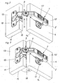
- Fig. 1 shows a corner cabinet 16, the recessed corner 29 of the movable furniture parts 4 and 11 is closed. Between these two furniture parts a folding door hinge is arranged for this purpose in the area A. This connects the two furniture parts 4 and 11 with each other such that when mounting the stop members 1 and 10 of the folding door hinge on the respective rear sides 12 and 13 of the furniture parts 4 and 11 the rear sides 12 and 13 opposite front sides 14 and 15 of the furniture parts 4 and 11 in at least one end position, here the closed position, an angle ⁇ of substantially 90 ° with each other. In differently shaped corner cabinets 16 or the like, another angle smaller 180 ° between the two front sides 14 and 15 may be provided. In comparison of the FIGS. 2 and 3 is shown the essential task of skew adjustment.
- Fig. 3 shows, albeit in a perspective view, the angle ⁇ between the fronts 14 and 15 of the furniture parts 4 and 11th
- a stop parts of the hinge arm 1 and the hinge cup 10 is provided as a stop parts of the hinge arm 1 and the hinge cup 10 .
- the pivotable connection between the hinge arm and pot or the stop members can, as known in the art, are executed.
- the hinge arm 1 can be clipped on a base plate 17 as in this embodiment.
- these embodiments of the stop members are to be regarded as examples only.
- Essential for a Faltten hinge is that a stop member - here the hinge arm 1 - has a first region 2 for attachment to a furniture part 4 or the like and a contrast angled second region 3, which in turn is adjustable in length.
- the length adjustment of the area 3 is achieved by the transmission device 5 according to the invention for converting a rotational movement into a longitudinal movement.
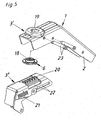
- the transmission device 5 has in the embodiment according to the Fig. 2 to 5 as an essential component of a spiral gate 6.
- the second region 3 of the stop member 1 is constructed in two parts. It has two mutually displaceable, substantially U-shaped profiles 3 'and 3 "in the component 3" are two guide slots 22, in which engage the guide pins 23 of the component 3', arranged. In the fully assembled arrangement, the two components 3 'and 3 "along the guide slots 22 against each other, which is a prerequisite for the length adjustment in the area 3 of the stop member 1.
- the guide housing 19 of the component 3 'mounted spiral gate 6 in the provided on the component 3 "toothing 20 a.
- the spiral backdrop 6 is rotated by means of the slots 18, in which, for example, a screwdriver can be inserted.
- the two components 3 'and 3 are displaced relative to each other as a result of the rotation of the helical connecting links 6 in the toothing 20.
- a marking 21, for example on the component 3". it is additionally possible to use a marking 21, for example on the component 3". , be provided.
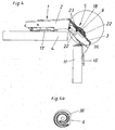
- Fig. 4 the area 3 is shown in section H cut.
- Fig. 4a shows a view from below of the spiral sliding gate 30 with which the spiral gate 6 engages the toothing 20.
- a self-locking embodiment of this embodiment can be achieved by a correspondingly close fit of the two components 3 'and 3 "on each other in interaction with the spiral gate 6 itself Region 2 and the second region 3 of the stop member 1 is here substantially 45 °. However, other angles, for example between 40 ° and 50 °, can be provided.
- the embodiment is favorably by a correspondingly close fit of the components 3 'and 3 "successive and the associated friction self-locking executed.
- the once set by means of the transmission device 5 for converting a rotational movement into a longitudinal movement length of the second region 3 then remains unchanged until the next targeted adjustment.
Landscapes
- Engineering & Computer Science (AREA)
- Mechanical Engineering (AREA)
- General Engineering & Computer Science (AREA)
- Hinges (AREA)
- Extensible Doors And Revolving Doors (AREA)
Description
- Die vorliegende Erfindung betrifft ein Falttürenscharnier für bewegbare Möbelteile, mit mindestens einem als Scharnierarm ausgebildeten Anschlagteil, wobei der Scharnierarm einen ersten Bereich zur Befestigung an einem Möbelteil und einen demgegenüber abgewinkelten und längenverstellbaren zweiten Bereich aufweist, wobei der zweite Bereich des Scharnierarmes zwei gegeneinander verschiebbare Scharnierarmteile aufweist.
- Falttürenscharniere werden dazu eingesetzt, zwei bewegbare Möbelteile, welche zum Beispiel die Tür im Bereich einer zurückspringenden Ecke einer Einbauküche oder dergleichen bilden, schwenkbar zu verbinden. Sie sind daher dazu geeignet, einen überstumpfen Winkel zu übergreifen. Um ein Falttürenscharnier für verschiedene Paneldicken der Möbelteile verwenden zu können, ist bereits eine so genannte Schrägverstellung bekannt. Diese ist beim Stand der Technik in dem abgewinkelten längenverstellbaren zweiten Bereich des Anschlagteiles als eine Kombination von Langloch und Klemmschraube ausgeführt. In dem Langloch müssen feine Verzahnungen vorgesehen sein, damit die Arretierung stabil aufrechterhalten werden kann. Für eine Verstellung muss die Klemmschraube zuerst gelöst werden, dann die Verstellung vorgenommen und anschließend die Klemmschraube wieder angezogen werden. Dies ist sehr aufwendig. Darüber hinaus müssen in der Regel gleichzeitig mindestens zwei Scharniere in gleicher Weise eingestellt werden, was durch die Notwendigkeit des Lösens der Klemmschrauben zu einem labilen Zwischenzustand führt. Ein weiterer Nachteil besteht darin, dass durch die Notwendigkeit der Verzahnung im Langloch eine stufenlose Verstellung nicht möglich ist.
- Solche gattungsgemäßen Falttürenscharniere sind beispielsweise in der
EP 0 463 439 A1 der Anmelderin sowie in derDE 92 03 048 U1 beschrieben. - Aufgabe der Erfindung ist es daher, die geschilderte Schrägverstellung für Falttürenscharniere dahingehend zu verbessern, dass eine möglichst einfache und stufenlose Verstellung möglich ist.
- Dies wird erfindungsgemäß durch die Merkmale des Patentanspruchs 1 gelöst. Weitere vorteilhafte Ausgestaltungen der Erfindung sind in den abhängigen Unteransprüchen angegeben.
- Durch die Übertragungseinrichtung zur Umwandlung einer Drehbewegung in eine Längsbewegung ist es zur Schrägverstellung nicht mehr notwendig, eine Klemmschraube zu lösen und wieder anzuziehen. Das Falttürenscharnier sowie die daran befestigten Möbelteile bleiben während des gesamten Verstellvorgangs in einer stabilen Lage zueinander. Darüber hinaus ermöglicht die erfindungsgemäße Übertragungseinrichtung auch eine stufenlose Schrägverstellung. Hierbei ist es besonders günstig, wenn die Übertragungseinrichtung selbsthemmend ausgebildet ist, sie also ohne weiteres Zutun in jeder einmal eingestellten Stellung verbleibt. Die Übertragungseinrichtung ist günstigerweise direkt im zweiten Bereich des Anschlagteiles angeordnet, in dem die Längenverstellung auch vorgenommen werden soll.
- Verschiedene Ausgestaltungsformen sowie weitere Vorteile der Erfindung werden anhand der beigelegten Figuren erläutert. Dabei zeigen:
- Fig. 1
- eine typische Einbausituation für ein Falttürenscharnier,
- Fig. 2 bis 5
- ein Ausführungsbeispiel der Erfindung,
-
Fig. 1 zeigt einen Eckschrank 16, dessen zurückspringende Ecke 29 von den bewegbaren Möbelteilen 4 und 11 verschließbar ist. Zwischen diesen beiden Möbelteilen ist hierzu im Bereich A ein Falttürenscharnier angeordnet. Dies verbindet die beiden Möbelteile 4 und 11 derart miteinander, dass bei Montage der Anschlagteile 1 und 10 des Falttürenscharniers auf den jeweiligen Rückseiten 12 und 13 der Möbelteile 4 und 11 die den Rückseiten 12 und 13 gegenüberliegenden Frontseiten 14 und 15 der Möbelteile 4 und 11 in zumindest einer Endlage, hier der Schließstellung, einen Winkel α von im Wesentlichen 90° miteinander einschließen. Bei anders geformten Eckschränken 16 oder dergleichen kann auch ein anderer Winkel kleiner 180° zwischen den beiden Frontseiten 14 und 15 vorgesehen sein. Im Vergleich derFiguren 2 und 3 ist die wesentliche Aufgabe der Schrägverstellung gezeigt. So kann mittels der Schrägverstellung der Abstand der Möbelteile 4 und 11 zueinander eingestellt werden um damit zum Beispiel eine Anpassung an verschiedene Paneeldicken der Möbelteile zu ermöglichen.Fig. 3 zeigt, wenn auch in einer perspektivischen Darstellung, den Winkel α zwischen den Fronten 14 und 15 der Möbelteile 4 und 11. - In diesem Ausführungsbeispiel als Anschlagteile der Scharnierarm 1 und der Scharniertopf 10 vorgesehen. Die schwenkbare Verbindung zwischen Scharnierarm und -topf bzw. den Anschlagteilen kann, wie beim Stand der Technik bekannt, ausgeführt werden. Der Scharnierarm 1 kann wie in diesem Ausführungsbeispiel auf eine Grundplatte 17 aufklipsbar sein. Diese Ausgestaltungsformen der Anschlagteile sind jedoch nur als Beispiele anzusehen. Wesentlich für ein Falttürenscharnier ist, dass ein Anschlagteil - hier der Scharnierarm 1 - einen ersten Bereich 2 zur Befestigung an einem Möbelteil 4 oder dergleichen und einen demgegenüber abgewinkelten zweiten Bereich 3 aufweist, welcher wiederum längenverstellbar ist. Die Längenverstellung des Bereiches 3 wird durch die erfindungsgemäße Übertragungseinrichtung 5 zur Umwandlung einer Drehbewegung in eine Längsbewegung erreicht.
- Die Übertragungseinrichtung 5 weist im Ausführungsbeispiel gemäß den
Fig. 2 bis 5 als einen wesentlichen Bauteil eine spiralförmige Kulisse 6 auf. Der zweite Bereich 3 des Anschlagteiles 1 ist zweiteilig aufgebaut. Er weist zwei gegeneinander verschiebbare, im Wesentlichen U-förmige Profile 3' und 3" auf. Im Bauteil 3" sind zwei Führungsschlitze 22, in die die Führungsstifte 23 des Bauteils 3' eingreifen, angeordnet. In fertig montierter Anordnung sind so die beiden Bauteile 3' und 3" entlang der Führungsschlitze 22 gegeneinander verschiebbar, was eine Voraussetzung für die Längenverstellung im Bereich 3 des Anschlagteiles 1 ist. Um die gewünschte stufenlose und sehr einfach durchzuführende Längenverstellung erfindungsgemäß zu ermöglichen, greift in diesem Ausführungsbeispiel die in dem Führungsgehäuse 19 des Bauteils 3' gelagerte spiralförmige Kulisse 6 in die am Bauteil 3" vorgesehene Verzahnung 20 ein. Gedreht wird die spiralförmige Kulisse 6 mit Hilfe der Schlitze 18, in die zum Beispiel ein Schraubendreher eingeführt werden kann. Durch die Drehung der spiralförmigen Kulissen 6 in der Verzahnung 20 werden die beiden Bauteile 3' und 3" relativ zueinander verschoben. Um diese Art der Längen- bzw. Schrägverstellung genau vornehmen zu können, kann zusätzlich eine Markierung 21, zum Beispiel am Bauteil 3", vorgesehen sein. InFig. 4 ist der Bereich 3 im Ausschnitt H geschnitten dargestellt.Fig. 4a zeigt eine Ansicht von unten auf die spiralförmigen Kulissengänge 30 mit denen die spiralförmige Kulisse 6 in die Verzahnung 20 eingreift. Eine selbsthemmende Ausbildung dieses Ausführungsbeispiels kann durch einen entsprechend engen Sitz der beiden Bauteile 3' und 3" aufeinander im Zusammenspiel mit der spiralförmigen Kulisse 6 selbst erreicht werden. Die Abwinkelung zwischen dem ersten Bereich 2 und dem zweiten Bereich 3 des Anschlagteils 1 beträgt hier im Wesentlichen 45°. Es können aber auch andere Winkel, zum Beispiel zwischen 40° und 50°, vorgesehen sein. - Das Ausführungsbeispiel ist günstigerweise durch einen entsprechend engen Sitz der Bauteile 3' und 3" aufeinander und die damit verbundene Reibung selbsthemmend ausgeführt. Die einmal mittels der Übertragungseinrichtung 5 zur Umwandlung einer Drehbewegung in eine Längsbewegung eingestellte Länge des zweiten Bereiches 3 bleibt dann unverändert bis zur nächsten gezielten Verstellung erhalten.
Claims (6)
- Falttürenscharnier für bewegbare Möbelteile (4, 11), mit mindestens einem als Schamierarm ausgebildeten Anschlagteil (1), wobei der Scharnierarm (1) einen ersten Bereich (2) zur Befestigung an einem Möbelteil (4) und einen demgegenüber abgewinkelten und längenverstellbaren zweiten Bereich (3) aufweist, wobei der erste und der zweite Bereich (2, 3) einen Winkel zwischen 40° und 50°, insbesondere von im Wesentlichen 45°, miteinander einschließen, wobei der zweite Bereich (3) des Scharnierarmes (1) zwei gegeneinander verschiebbare Bauteile (3', 3") aufweist, dadurch gekennzeichnet, dass das Falttürenscharnier zur Längenverstellung des zweiten Bereiches (3) eine Übertragungseinrichtung (5) mit einer Aufnahme (18, 18') für ein Betätigungswerkzeug aufweist, wobei durch Drehung der Aufnahme (18, 18') mittels des Betätigungswerkzeuges die beiden Bauteile (3', 3") gegeneinander linear verschiebbar sind, wobei die Übertragungseinrichtung (5) eine an einem Bauteil (3') angeordnete, spiralförmige Kulisse (6) aufweist, welche durch Drehung der Aufnahme (18, 18') verdrehbar ist und welche in eine am anderen Bauteil (3") vorgesehene Verzahnung (20) eingreift.
- Falttürenscharnier nach Anspruch 1, dadurch gekennzeichnet, dass die Übertragungseinrichtung (5) selbsthemmend ausgebildet ist.
- Falttürenscharnier nach einem der Ansprüche 1 oder 2, dadurch gekennzeichnet, dass die Übertragungseinrichtung (5) im zweiten Bereich (3) des Anschlagteiles (1) angeordnet ist.
- Falttürenscharnier nach einem der Ansprüche 1 bis 3 mit einem als Scharnierarm (1) und einem als Scharniertopf (10) ausgebildeten Anschlagteil, dadurch gekennzeichnet, dass es dazu geeignet ist, zwei zueinander bewegliche Möbelteile (4, 11) miteinander derart zu verbinden, dass bei Montage des Scharnierarmes (1) und des Scharniertopfes (10) auf den jeweiligen Rückseiten (12, 13) der Möbelteile (4, 11) die den Rückseiten (12, 13) gegenüber liegenden Frontseiten (14, 15) der Möbelteile (4, 11) in zumindest einer Endlage einen Winkel (α) kleiner 180°, vorzugsweise einen Winkel von im Wesentlichen 90°, miteinander einschließen.
- Falttürenscharnier nach einem der Ansprüche 1 bis 4, dadurch gekennzeichnet, dass es einen als Scharniertopf (10) ausgebildeten Anschlagteil (10) aufweist.
- Falttürenscharnier nach einem der Ansprüche 1 bis 5, dadurch gekennzeichnet, dass die beiden Bauteile (3', 3") im Wesentlichen als U-förmige Profile ausgebildet sind.
Priority Applications (1)
| Application Number | Priority Date | Filing Date | Title |
|---|---|---|---|
| SI200531887T SI1653031T1 (sl) | 2004-10-28 | 2005-08-31 | Zgibni šarnir vrat |
Applications Claiming Priority (1)
| Application Number | Priority Date | Filing Date | Title |
|---|---|---|---|
| AT0181504A AT501396B1 (de) | 2004-10-28 | 2004-10-28 | Falttürenscharnier |
Publications (3)
| Publication Number | Publication Date |
|---|---|
| EP1653031A2 EP1653031A2 (de) | 2006-05-03 |
| EP1653031A3 EP1653031A3 (de) | 2008-06-04 |
| EP1653031B1 true EP1653031B1 (de) | 2014-06-11 |
Family
ID=35781470
Family Applications (1)
| Application Number | Title | Priority Date | Filing Date |
|---|---|---|---|
| EP05018881.2A Expired - Lifetime EP1653031B1 (de) | 2004-10-28 | 2005-08-31 | Falttürenscharnier |
Country Status (6)
| Country | Link |
|---|---|
| US (1) | US8707517B2 (de) |
| EP (1) | EP1653031B1 (de) |
| CN (1) | CN1766270B (de) |
| AT (1) | AT501396B1 (de) |
| ES (1) | ES2496103T3 (de) |
| SI (1) | SI1653031T1 (de) |
Families Citing this family (16)
| Publication number | Priority date | Publication date | Assignee | Title |
|---|---|---|---|---|
| US20110017692A1 (en) * | 2009-07-24 | 2011-01-27 | Slam Brands, Inc. | Hinge apparatuses, structures, and systems for structurally rigid and durable, folding support furniture |
| JP5606058B2 (ja) * | 2009-12-24 | 2014-10-15 | 株式会社陽洋 | 隠し蝶番 |
| CN102116121B (zh) * | 2011-01-31 | 2012-07-25 | 冯志平 | 一种折叠门 |
| CN102720416B (zh) * | 2012-05-21 | 2014-10-15 | 品谱五金家居(深圳)有限公司 | 中间铰链组件 |
| JP6013588B2 (ja) * | 2013-11-11 | 2016-10-25 | スガツネ工業株式会社 | ヒンジ装置及びヒンジ装置基部 |
| DE202014102477U1 (de) * | 2014-05-27 | 2015-08-28 | Grass Gmbh & Co. Kg | Verstellbarer Steuerhebel |
| DE102015226543A1 (de) * | 2015-12-22 | 2017-06-22 | Rolls-Royce Deutschland Ltd & Co Kg | Triebwerksverkleidung |
| DE202016006655U1 (de) * | 2016-10-28 | 2018-02-01 | Hetal-Werke Franz Hettich Gmbh & Co. Kg | Eckschrank |
| DE202016006656U1 (de) * | 2016-10-28 | 2018-02-01 | Hetal-Werke Franz Hettich Gmbh & Co. Kg | Steuervorrichtung zur Bewegungssteuerung einer Eckschranktür eines Eckschranks |
| AT519898B1 (de) * | 2017-05-11 | 2019-12-15 | Blum Gmbh Julius | Beschlag für eine Falttür |
| CN108716330A (zh) * | 2018-05-17 | 2018-10-30 | 青岛海尔股份有限公司 | 冰箱及其铰链装置 |
| US11124999B2 (en) | 2019-11-11 | 2021-09-21 | Snap-On Incorporated | Adjustable door hinge mechanism |
| CN111088917A (zh) * | 2020-01-17 | 2020-05-01 | 广东星徽精密制造股份有限公司 | 一种铰链快速拆卸锁离调节装置 |
| CN111809993B (zh) * | 2020-07-14 | 2021-12-17 | 杭州宏利工贸有限公司 | 一种不锈钢铰链 |
| AT524607B1 (de) * | 2020-12-17 | 2024-02-15 | Blum Gmbh Julius | Anordnung zur Führung eines bewegbaren Möbelteils |
| TWI783789B (zh) * | 2021-11-23 | 2022-11-11 | 富世達股份有限公司 | 前後滑動式鉸鏈 |
Citations (1)
| Publication number | Priority date | Publication date | Assignee | Title |
|---|---|---|---|---|
| EP1367203A2 (de) * | 2002-05-29 | 2003-12-03 | Arturo Salice S.p.A. | Scharnier |
Family Cites Families (16)
| Publication number | Priority date | Publication date | Assignee | Title |
|---|---|---|---|---|
| BR7706984A (pt) * | 1976-10-22 | 1978-06-27 | Heinze R | Dobradica para moveis |
| DE3521051A1 (de) * | 1985-06-12 | 1986-12-18 | Arturo Salice S.P.A., Novedrate, Como | Scharnierarm fuer ein moebelscharnier mit befestigungsplatte |
| CN2094650U (zh) * | 1990-01-24 | 1992-01-29 | 刘东英 | 无级变速器 |
| AT397407B (de) * | 1990-06-25 | 1994-04-25 | Blum Gmbh Julius | Scharnier |
| US5201096A (en) * | 1990-06-25 | 1993-04-13 | Julius Blum Gesellschaft M.B.H. | Hinge |
| DE9203048U1 (de) * | 1992-03-07 | 1992-04-23 | Paul Hettich GmbH & Co, 4983 Kirchlengern | Eckschrankscharnier |
| US5283929A (en) * | 1992-06-01 | 1994-02-08 | Lin Tsong Chi | Hinge |
| AT1214U1 (de) * | 1995-12-18 | 1996-12-27 | Blum Gmbh Julius | Scharnier |
| AT407277B (de) * | 1998-08-11 | 2001-02-26 | Blum Gmbh Julius | Scharnier |
| AT409157B (de) * | 1999-02-17 | 2002-06-25 | Blum Gmbh Julius | Scharnier |
| CN2406023Y (zh) * | 2000-02-21 | 2000-11-15 | 伍志勇 | 家具用暗铰链 |
| FR2829792B3 (fr) * | 2001-09-14 | 2003-09-05 | Alias S R L | Charniere invisible reglable pour portes, fermetures ou analogues |
| DE10210017C1 (de) * | 2002-03-07 | 2003-07-31 | Grass Gmbh Hoechst | Möbelscharnier mit Verstelleinrichtung |
| AT6168U1 (de) * | 2002-07-15 | 2003-05-26 | Blum Gmbh Julius | Scharnier |
| AT6963U1 (de) * | 2003-02-21 | 2004-06-25 | Blum Gmbh Julius | Scharnier |
| AT6962U1 (de) * | 2003-02-21 | 2004-06-25 | Blum Gmbh Julius | Scharnier |
-
2004
- 2004-10-28 AT AT0181504A patent/AT501396B1/de not_active IP Right Cessation
-
2005
- 2005-08-31 ES ES05018881.2T patent/ES2496103T3/es not_active Expired - Lifetime
- 2005-08-31 SI SI200531887T patent/SI1653031T1/sl unknown
- 2005-08-31 EP EP05018881.2A patent/EP1653031B1/de not_active Expired - Lifetime
- 2005-10-18 US US11/251,935 patent/US8707517B2/en active Active
- 2005-10-20 CN CN2005101164226A patent/CN1766270B/zh not_active Expired - Lifetime
Patent Citations (1)
| Publication number | Priority date | Publication date | Assignee | Title |
|---|---|---|---|---|
| EP1367203A2 (de) * | 2002-05-29 | 2003-12-03 | Arturo Salice S.p.A. | Scharnier |
Also Published As
| Publication number | Publication date |
|---|---|
| AT501396A1 (de) | 2006-08-15 |
| SI1653031T1 (sl) | 2014-10-30 |
| ES2496103T3 (es) | 2014-09-18 |
| US8707517B2 (en) | 2014-04-29 |
| AT501396B1 (de) | 2007-10-15 |
| CN1766270B (zh) | 2012-08-29 |
| EP1653031A3 (de) | 2008-06-04 |
| US20060090295A1 (en) | 2006-05-04 |
| EP1653031A2 (de) | 2006-05-03 |
| CN1766270A (zh) | 2006-05-03 |
Similar Documents
| Publication | Publication Date | Title |
|---|---|---|
| EP3612700B1 (de) | Möbelplatte mit einem klappenbeschlag und möbelkorpus sowie möbel mit einer derartigen möbelplatte | |
| EP2222202B1 (de) | Schubkasten mit Frontverstellung | |
| EP2527576B1 (de) | Scharnier insbesondere für eine Verschiebevorrichtung | |
| EP0761130B1 (de) | Halterungs-Beschlag für Frontblenden von Schubladen | |
| EP2704604B1 (de) | Schubkasten | |
| AT501396B1 (de) | Falttürenscharnier | |
| EP3088645B1 (de) | Verbindungsvorrichtung für eine schiebetür | |
| DE202004000652U1 (de) | Scharnier | |
| EP2742199B1 (de) | Befestigungsanordnung zur befestigung eines bauteils an einer nut eines fensters, einer tür oder dergleichen | |
| EP2297418B1 (de) | Scharnier | |
| DE202015103874U1 (de) | Vorrichtung zum Verbinden zweier Möbelteile | |
| EP2206861B1 (de) | Türbandanordnung | |
| WO2018033221A1 (de) | Möbelscharnier | |
| EP2294957A2 (de) | Vorrichtung zur Halterung von flächenförmigen Elementen | |
| EP3621483B1 (de) | Haltevorrichtung für eine frontblende einer schublade | |
| EP2526820A1 (de) | Schrankauszug | |
| EP1132560B1 (de) | Scharnier, sowie Verfahren zur Höhenverstellung eines Scharniers | |
| EP2149664B1 (de) | Unterkonstruktion für ein Scharnierband und Scharnierband mit einer solchen Unterkonstruktion zur Befestigung an einem Türblatt | |
| EP1577476B1 (de) | Scharnier zur drehbaren Halterung einer Tür oder eines Fensters an einem Rahmen | |
| EP2208843B1 (de) | Scharnier für eine Tür | |
| EP2024592A1 (de) | Band mit justierung | |
| DE102017126368A1 (de) | Möbelplatte mit einem Klappenbeschlag und Möbelkorpus sowie Möbel mit einer derartigen Möbelplatte | |
| DE202008016071U1 (de) | Band zur scharniergelenkigen Verbindung eines Flügels an einem Rahmen | |
| DE3217104C2 (de) | ||
| AT503457B1 (de) | Scharnier für die verschwenkbare anlenkung von klappen oder türflügeln am korpus von möbelstücken |
Legal Events
| Date | Code | Title | Description |
|---|---|---|---|
| PUAI | Public reference made under article 153(3) epc to a published international application that has entered the european phase |
Free format text: ORIGINAL CODE: 0009012 |
|
| AK | Designated contracting states |
Kind code of ref document: A2 Designated state(s): AT BE BG CH CY CZ DE DK EE ES FI FR GB GR HU IE IS IT LI LT LU LV MC NL PL PT RO SE SI SK TR |
|
| AX | Request for extension of the european patent |
Extension state: AL BA HR MK YU |
|
| PUAL | Search report despatched |
Free format text: ORIGINAL CODE: 0009013 |
|
| AK | Designated contracting states |
Kind code of ref document: A3 Designated state(s): AT BE BG CH CY CZ DE DK EE ES FI FR GB GR HU IE IS IT LI LT LU LV MC NL PL PT RO SE SI SK TR |
|
| AX | Request for extension of the european patent |
Extension state: AL BA HR MK YU |
|
| 17P | Request for examination filed |
Effective date: 20080606 |
|
| 17Q | First examination report despatched |
Effective date: 20080918 |
|
| AKX | Designation fees paid |
Designated state(s): AT BE BG CH CY CZ DE DK EE ES FI FR GB GR HU IE IS IT LI LT LU LV MC NL PL PT RO SE SI SK TR |
|
| R17C | First examination report despatched (corrected) |
Effective date: 20090331 |
|
| GRAP | Despatch of communication of intention to grant a patent |
Free format text: ORIGINAL CODE: EPIDOSNIGR1 |
|
| INTG | Intention to grant announced |
Effective date: 20140120 |
|
| GRAS | Grant fee paid |
Free format text: ORIGINAL CODE: EPIDOSNIGR3 |
|
| GRAA | (expected) grant |
Free format text: ORIGINAL CODE: 0009210 |
|
| AK | Designated contracting states |
Kind code of ref document: B1 Designated state(s): AT BE BG CH CY CZ DE DK EE ES FI FR GB GR HU IE IS IT LI LT LU LV MC NL PL PT RO SE SI SK TR |
|
| REG | Reference to a national code |
Ref country code: GB Ref legal event code: FG4D Free format text: NOT ENGLISH |
|
| REG | Reference to a national code |
Ref country code: CH Ref legal event code: EP |
|
| REG | Reference to a national code |
Ref country code: IE Ref legal event code: FG4D Free format text: LANGUAGE OF EP DOCUMENT: GERMAN |
|
| REG | Reference to a national code |
Ref country code: AT Ref legal event code: REF Ref document number: 672360 Country of ref document: AT Kind code of ref document: T Effective date: 20140715 |
|
| REG | Reference to a national code |
Ref country code: DE Ref legal event code: R096 Ref document number: 502005014390 Country of ref document: DE Effective date: 20140717 |
|
| REG | Reference to a national code |
Ref country code: ES Ref legal event code: FG2A Ref document number: 2496103 Country of ref document: ES Kind code of ref document: T3 Effective date: 20140918 |
|
| PG25 | Lapsed in a contracting state [announced via postgrant information from national office to epo] |
Ref country code: FI Free format text: LAPSE BECAUSE OF FAILURE TO SUBMIT A TRANSLATION OF THE DESCRIPTION OR TO PAY THE FEE WITHIN THE PRESCRIBED TIME-LIMIT Effective date: 20140611 Ref country code: GR Free format text: LAPSE BECAUSE OF FAILURE TO SUBMIT A TRANSLATION OF THE DESCRIPTION OR TO PAY THE FEE WITHIN THE PRESCRIBED TIME-LIMIT Effective date: 20140912 Ref country code: LT Free format text: LAPSE BECAUSE OF FAILURE TO SUBMIT A TRANSLATION OF THE DESCRIPTION OR TO PAY THE FEE WITHIN THE PRESCRIBED TIME-LIMIT Effective date: 20140611 |
|
| REG | Reference to a national code |
Ref country code: NL Ref legal event code: VDEP Effective date: 20140611 |
|
| REG | Reference to a national code |
Ref country code: LT Ref legal event code: MG4D |
|
| PG25 | Lapsed in a contracting state [announced via postgrant information from national office to epo] |
Ref country code: LV Free format text: LAPSE BECAUSE OF FAILURE TO SUBMIT A TRANSLATION OF THE DESCRIPTION OR TO PAY THE FEE WITHIN THE PRESCRIBED TIME-LIMIT Effective date: 20140611 Ref country code: SE Free format text: LAPSE BECAUSE OF FAILURE TO SUBMIT A TRANSLATION OF THE DESCRIPTION OR TO PAY THE FEE WITHIN THE PRESCRIBED TIME-LIMIT Effective date: 20140611 |
|
| PG25 | Lapsed in a contracting state [announced via postgrant information from national office to epo] |
Ref country code: EE Free format text: LAPSE BECAUSE OF FAILURE TO SUBMIT A TRANSLATION OF THE DESCRIPTION OR TO PAY THE FEE WITHIN THE PRESCRIBED TIME-LIMIT Effective date: 20140611 Ref country code: PT Free format text: LAPSE BECAUSE OF FAILURE TO SUBMIT A TRANSLATION OF THE DESCRIPTION OR TO PAY THE FEE WITHIN THE PRESCRIBED TIME-LIMIT Effective date: 20141013 Ref country code: SK Free format text: LAPSE BECAUSE OF FAILURE TO SUBMIT A TRANSLATION OF THE DESCRIPTION OR TO PAY THE FEE WITHIN THE PRESCRIBED TIME-LIMIT Effective date: 20140611 Ref country code: RO Free format text: LAPSE BECAUSE OF FAILURE TO SUBMIT A TRANSLATION OF THE DESCRIPTION OR TO PAY THE FEE WITHIN THE PRESCRIBED TIME-LIMIT Effective date: 20140611 Ref country code: CZ Free format text: LAPSE BECAUSE OF FAILURE TO SUBMIT A TRANSLATION OF THE DESCRIPTION OR TO PAY THE FEE WITHIN THE PRESCRIBED TIME-LIMIT Effective date: 20140611 |
|
| PG25 | Lapsed in a contracting state [announced via postgrant information from national office to epo] |
Ref country code: IS Free format text: LAPSE BECAUSE OF FAILURE TO SUBMIT A TRANSLATION OF THE DESCRIPTION OR TO PAY THE FEE WITHIN THE PRESCRIBED TIME-LIMIT Effective date: 20141011 Ref country code: NL Free format text: LAPSE BECAUSE OF FAILURE TO SUBMIT A TRANSLATION OF THE DESCRIPTION OR TO PAY THE FEE WITHIN THE PRESCRIBED TIME-LIMIT Effective date: 20140611 Ref country code: PL Free format text: LAPSE BECAUSE OF FAILURE TO SUBMIT A TRANSLATION OF THE DESCRIPTION OR TO PAY THE FEE WITHIN THE PRESCRIBED TIME-LIMIT Effective date: 20140611 |
|
| REG | Reference to a national code |
Ref country code: DE Ref legal event code: R097 Ref document number: 502005014390 Country of ref document: DE |
|
| PG25 | Lapsed in a contracting state [announced via postgrant information from national office to epo] |
Ref country code: LU Free format text: LAPSE BECAUSE OF FAILURE TO SUBMIT A TRANSLATION OF THE DESCRIPTION OR TO PAY THE FEE WITHIN THE PRESCRIBED TIME-LIMIT Effective date: 20140831 Ref country code: MC Free format text: LAPSE BECAUSE OF FAILURE TO SUBMIT A TRANSLATION OF THE DESCRIPTION OR TO PAY THE FEE WITHIN THE PRESCRIBED TIME-LIMIT Effective date: 20140611 |
|
| REG | Reference to a national code |
Ref country code: CH Ref legal event code: PL |
|
| PLBE | No opposition filed within time limit |
Free format text: ORIGINAL CODE: 0009261 |
|
| STAA | Information on the status of an ep patent application or granted ep patent |
Free format text: STATUS: NO OPPOSITION FILED WITHIN TIME LIMIT |
|
| PG25 | Lapsed in a contracting state [announced via postgrant information from national office to epo] |
Ref country code: CH Free format text: LAPSE BECAUSE OF NON-PAYMENT OF DUE FEES Effective date: 20140831 Ref country code: BE Free format text: LAPSE BECAUSE OF NON-PAYMENT OF DUE FEES Effective date: 20140831 Ref country code: LI Free format text: LAPSE BECAUSE OF NON-PAYMENT OF DUE FEES Effective date: 20140831 Ref country code: DK Free format text: LAPSE BECAUSE OF FAILURE TO SUBMIT A TRANSLATION OF THE DESCRIPTION OR TO PAY THE FEE WITHIN THE PRESCRIBED TIME-LIMIT Effective date: 20140611 |
|
| 26N | No opposition filed |
Effective date: 20150312 |
|
| REG | Reference to a national code |
Ref country code: FR Ref legal event code: ST Effective date: 20150430 |
|
| REG | Reference to a national code |
Ref country code: IE Ref legal event code: MM4A |
|
| REG | Reference to a national code |
Ref country code: DE Ref legal event code: R097 Ref document number: 502005014390 Country of ref document: DE Effective date: 20150312 |
|
| PG25 | Lapsed in a contracting state [announced via postgrant information from national office to epo] |
Ref country code: IE Free format text: LAPSE BECAUSE OF NON-PAYMENT OF DUE FEES Effective date: 20140831 Ref country code: FR Free format text: LAPSE BECAUSE OF NON-PAYMENT OF DUE FEES Effective date: 20140901 |
|
| PG25 | Lapsed in a contracting state [announced via postgrant information from national office to epo] |
Ref country code: BG Free format text: LAPSE BECAUSE OF FAILURE TO SUBMIT A TRANSLATION OF THE DESCRIPTION OR TO PAY THE FEE WITHIN THE PRESCRIBED TIME-LIMIT Effective date: 20140611 |
|
| PG25 | Lapsed in a contracting state [announced via postgrant information from national office to epo] |
Ref country code: CY Free format text: LAPSE BECAUSE OF FAILURE TO SUBMIT A TRANSLATION OF THE DESCRIPTION OR TO PAY THE FEE WITHIN THE PRESCRIBED TIME-LIMIT Effective date: 20140611 |
|
| PG25 | Lapsed in a contracting state [announced via postgrant information from national office to epo] |
Ref country code: HU Free format text: LAPSE BECAUSE OF FAILURE TO SUBMIT A TRANSLATION OF THE DESCRIPTION OR TO PAY THE FEE WITHIN THE PRESCRIBED TIME-LIMIT; INVALID AB INITIO Effective date: 20050831 |
|
| P01 | Opt-out of the competence of the unified patent court (upc) registered |
Effective date: 20230523 |
|
| PGFP | Annual fee paid to national office [announced via postgrant information from national office to epo] |
Ref country code: DE Payment date: 20240828 Year of fee payment: 20 |
|
| PGFP | Annual fee paid to national office [announced via postgrant information from national office to epo] |
Ref country code: GB Payment date: 20240819 Year of fee payment: 20 |
|
| PGFP | Annual fee paid to national office [announced via postgrant information from national office to epo] |
Ref country code: ES Payment date: 20240918 Year of fee payment: 20 |
|
| PGFP | Annual fee paid to national office [announced via postgrant information from national office to epo] |
Ref country code: AT Payment date: 20240826 Year of fee payment: 20 |
|
| PGFP | Annual fee paid to national office [announced via postgrant information from national office to epo] |
Ref country code: SI Payment date: 20240723 Year of fee payment: 20 |
|
| PGFP | Annual fee paid to national office [announced via postgrant information from national office to epo] |
Ref country code: IT Payment date: 20240826 Year of fee payment: 20 |
|
| PGFP | Annual fee paid to national office [announced via postgrant information from national office to epo] |
Ref country code: TR Payment date: 20240725 Year of fee payment: 20 |
|
| REG | Reference to a national code |
Ref country code: DE Ref legal event code: R071 Ref document number: 502005014390 Country of ref document: DE |
|
| REG | Reference to a national code |
Ref country code: GB Ref legal event code: PE20 Expiry date: 20250830 |
|
| REG | Reference to a national code |
Ref country code: ES Ref legal event code: FD2A Effective date: 20250926 |
|
| PG25 | Lapsed in a contracting state [announced via postgrant information from national office to epo] |
Ref country code: ES Free format text: LAPSE BECAUSE OF EXPIRATION OF PROTECTION Effective date: 20250901 |
|
| REG | Reference to a national code |
Ref country code: AT Ref legal event code: MK07 Ref document number: 672360 Country of ref document: AT Kind code of ref document: T Effective date: 20250831 |