EP1651914B1 - Dichtungsprofil für einen kühlgeräteschiebedeckel - Google Patents
Dichtungsprofil für einen kühlgeräteschiebedeckel Download PDFInfo
- Publication number
- EP1651914B1 EP1651914B1 EP03789114A EP03789114A EP1651914B1 EP 1651914 B1 EP1651914 B1 EP 1651914B1 EP 03789114 A EP03789114 A EP 03789114A EP 03789114 A EP03789114 A EP 03789114A EP 1651914 B1 EP1651914 B1 EP 1651914B1
- Authority
- EP
- European Patent Office
- Prior art keywords
- sealing
- sliding cover
- seal
- sliding
- strips
- Prior art date
- Legal status (The legal status is an assumption and is not a legal conclusion. Google has not performed a legal analysis and makes no representation as to the accuracy of the status listed.)
- Expired - Lifetime
Links
- 238000007789 sealing Methods 0.000 title claims description 104
- 238000001816 cooling Methods 0.000 title claims description 18
- -1 polyoxymethylene Polymers 0.000 claims description 44
- 239000000203 mixture Substances 0.000 claims description 26
- 239000000463 material Substances 0.000 claims description 24
- 229920002725 thermoplastic elastomer Polymers 0.000 claims description 15
- 239000004952 Polyamide Substances 0.000 claims description 12
- 229920003229 poly(methyl methacrylate) Polymers 0.000 claims description 12
- 229920002647 polyamide Polymers 0.000 claims description 12
- 229920001707 polybutylene terephthalate Polymers 0.000 claims description 12
- 239000004417 polycarbonate Substances 0.000 claims description 12
- 229920000515 polycarbonate Polymers 0.000 claims description 12
- 229920000139 polyethylene terephthalate Polymers 0.000 claims description 12
- 239000005020 polyethylene terephthalate Substances 0.000 claims description 12
- 229920001155 polypropylene Polymers 0.000 claims description 12
- 239000004926 polymethyl methacrylate Substances 0.000 claims description 11
- 239000004800 polyvinyl chloride Substances 0.000 claims description 11
- 229920000915 polyvinyl chloride Polymers 0.000 claims description 11
- 239000004743 Polypropylene Substances 0.000 claims description 9
- 229920003048 styrene butadiene rubber Polymers 0.000 claims description 9
- 229920001169 thermoplastic Polymers 0.000 claims description 7
- 229930040373 Paraformaldehyde Natural products 0.000 claims description 6
- 239000004698 Polyethylene Substances 0.000 claims description 6
- PPBRXRYQALVLMV-UHFFFAOYSA-N Styrene Chemical compound C=CC1=CC=CC=C1 PPBRXRYQALVLMV-UHFFFAOYSA-N 0.000 claims description 6
- 239000002174 Styrene-butadiene Substances 0.000 claims description 6
- 229920000573 polyethylene Polymers 0.000 claims description 6
- 239000002861 polymer material Substances 0.000 claims description 6
- 229920006324 polyoxymethylene Polymers 0.000 claims description 6
- 239000011115 styrene butadiene Substances 0.000 claims description 6
- 150000001336 alkenes Chemical class 0.000 claims description 5
- 230000015572 biosynthetic process Effects 0.000 claims description 5
- 229920001577 copolymer Polymers 0.000 claims description 5
- 238000013016 damping Methods 0.000 claims description 5
- JRZJOMJEPLMPRA-UHFFFAOYSA-N olefin Natural products CCCCCCCC=C JRZJOMJEPLMPRA-UHFFFAOYSA-N 0.000 claims description 5
- 229920002614 Polyether block amide Polymers 0.000 claims description 3
- MSKQYWJTFPOQAV-UHFFFAOYSA-N fluoroethene;prop-1-ene Chemical group CC=C.FC=C MSKQYWJTFPOQAV-UHFFFAOYSA-N 0.000 claims description 3
- 239000004811 fluoropolymer Substances 0.000 claims description 3
- 229920002313 fluoropolymer Polymers 0.000 claims description 3
- 238000003780 insertion Methods 0.000 claims description 3
- 230000037431 insertion Effects 0.000 claims description 3
- 229920002635 polyurethane Polymers 0.000 claims description 2
- 239000004814 polyurethane Substances 0.000 claims description 2
- 239000004721 Polyphenylene oxide Substances 0.000 claims 5
- 229920006380 polyphenylene oxide Polymers 0.000 claims 4
- MTAZNLWOLGHBHU-UHFFFAOYSA-N butadiene-styrene rubber Chemical compound C=CC=C.C=CC1=CC=CC=C1 MTAZNLWOLGHBHU-UHFFFAOYSA-N 0.000 claims 2
- 229920001343 polytetrafluoroethylene Polymers 0.000 claims 2
- 239000004810 polytetrafluoroethylene Substances 0.000 claims 2
- YAAQEISEHDUIFO-UHFFFAOYSA-N C=CC#N.OC(=O)C=CC=CC1=CC=CC=C1 Chemical compound C=CC#N.OC(=O)C=CC=CC1=CC=CC=C1 YAAQEISEHDUIFO-UHFFFAOYSA-N 0.000 claims 1
- 229920012485 Plasticized Polyvinyl chloride Polymers 0.000 claims 1
- 229920002877 acrylic styrene acrylonitrile Polymers 0.000 claims 1
- 150000002148 esters Chemical class 0.000 claims 1
- 238000002955 isolation Methods 0.000 claims 1
- 230000002093 peripheral effect Effects 0.000 claims 1
- 229920000570 polyether Polymers 0.000 claims 1
- 229920000265 Polyparaphenylene Polymers 0.000 description 8
- 238000006073 displacement reaction Methods 0.000 description 4
- 238000000034 method Methods 0.000 description 4
- 239000004416 thermosoftening plastic Substances 0.000 description 4
- 229920001971 elastomer Polymers 0.000 description 3
- 239000000806 elastomer Substances 0.000 description 3
- 229920003023 plastic Polymers 0.000 description 3
- 239000004033 plastic Substances 0.000 description 3
- 229920000642 polymer Polymers 0.000 description 3
- 239000003566 sealing material Substances 0.000 description 3
- 230000002411 adverse Effects 0.000 description 2
- 230000002238 attenuated effect Effects 0.000 description 2
- 230000007423 decrease Effects 0.000 description 2
- 230000000694 effects Effects 0.000 description 2
- 238000004519 manufacturing process Methods 0.000 description 2
- 229920001909 styrene-acrylic polymer Polymers 0.000 description 2
- 239000004433 Thermoplastic polyurethane Substances 0.000 description 1
- 238000005299 abrasion Methods 0.000 description 1
- 239000011324 bead Substances 0.000 description 1
- 238000005452 bending Methods 0.000 description 1
- 238000009833 condensation Methods 0.000 description 1
- 230000005494 condensation Effects 0.000 description 1
- 230000006735 deficit Effects 0.000 description 1
- 230000001419 dependent effect Effects 0.000 description 1
- 238000013461 design Methods 0.000 description 1
- 238000011161 development Methods 0.000 description 1
- 230000018109 developmental process Effects 0.000 description 1
- 238000009826 distribution Methods 0.000 description 1
- 238000002474 experimental method Methods 0.000 description 1
- 239000011521 glass Substances 0.000 description 1
- 239000004014 plasticizer Substances 0.000 description 1
- 230000036316 preload Effects 0.000 description 1
- 238000002360 preparation method Methods 0.000 description 1
- 238000003825 pressing Methods 0.000 description 1
- 230000035882 stress Effects 0.000 description 1
- 238000005382 thermal cycling Methods 0.000 description 1
- 230000008646 thermal stress Effects 0.000 description 1
- 229920002397 thermoplastic olefin Polymers 0.000 description 1
- 229920002803 thermoplastic polyurethane Polymers 0.000 description 1
Images

Classifications
-
- E—FIXED CONSTRUCTIONS
- E06—DOORS, WINDOWS, SHUTTERS, OR ROLLER BLINDS IN GENERAL; LADDERS
- E06B—FIXED OR MOVABLE CLOSURES FOR OPENINGS IN BUILDINGS, VEHICLES, FENCES OR LIKE ENCLOSURES IN GENERAL, e.g. DOORS, WINDOWS, BLINDS, GATES
- E06B7/00—Special arrangements or measures in connection with doors or windows
- E06B7/16—Sealing arrangements on wings or parts co-operating with the wings
- E06B7/22—Sealing arrangements on wings or parts co-operating with the wings by means of elastic edgings, e.g. elastic rubber tubes; by means of resilient edgings, e.g. felt or plush strips, resilient metal strips
- E06B7/23—Plastic, sponge rubber, or like strips or tubes
- E06B7/2314—Plastic, sponge rubber, or like strips or tubes characterised by the material
-
- E—FIXED CONSTRUCTIONS
- E06—DOORS, WINDOWS, SHUTTERS, OR ROLLER BLINDS IN GENERAL; LADDERS
- E06B—FIXED OR MOVABLE CLOSURES FOR OPENINGS IN BUILDINGS, VEHICLES, FENCES OR LIKE ENCLOSURES IN GENERAL, e.g. DOORS, WINDOWS, BLINDS, GATES
- E06B7/00—Special arrangements or measures in connection with doors or windows
- E06B7/16—Sealing arrangements on wings or parts co-operating with the wings
- E06B7/22—Sealing arrangements on wings or parts co-operating with the wings by means of elastic edgings, e.g. elastic rubber tubes; by means of resilient edgings, e.g. felt or plush strips, resilient metal strips
- E06B7/23—Plastic, sponge rubber, or like strips or tubes
- E06B7/2305—Plastic, sponge rubber, or like strips or tubes with an integrally formed part for fixing the edging
- E06B7/2307—Plastic, sponge rubber, or like strips or tubes with an integrally formed part for fixing the edging with a single sealing-line or -plane between the wing and the part co-operating with the wing
- E06B7/2309—Plastic, sponge rubber, or like strips or tubes with an integrally formed part for fixing the edging with a single sealing-line or -plane between the wing and the part co-operating with the wing with a hollow sealing part
-
- F—MECHANICAL ENGINEERING; LIGHTING; HEATING; WEAPONS; BLASTING
- F25—REFRIGERATION OR COOLING; COMBINED HEATING AND REFRIGERATION SYSTEMS; HEAT PUMP SYSTEMS; MANUFACTURE OR STORAGE OF ICE; LIQUEFACTION SOLIDIFICATION OF GASES
- F25D—REFRIGERATORS; COLD ROOMS; ICE-BOXES; COOLING OR FREEZING APPARATUS NOT OTHERWISE PROVIDED FOR
- F25D23/00—General constructional features
- F25D23/08—Parts formed wholly or mainly of plastics materials
- F25D23/082—Strips
- F25D23/087—Sealing strips
-
- F—MECHANICAL ENGINEERING; LIGHTING; HEATING; WEAPONS; BLASTING
- F25—REFRIGERATION OR COOLING; COMBINED HEATING AND REFRIGERATION SYSTEMS; HEAT PUMP SYSTEMS; MANUFACTURE OR STORAGE OF ICE; LIQUEFACTION SOLIDIFICATION OF GASES
- F25D—REFRIGERATORS; COLD ROOMS; ICE-BOXES; COOLING OR FREEZING APPARATUS NOT OTHERWISE PROVIDED FOR
- F25D2201/00—Insulation
- F25D2201/30—Insulation with respect to sound
-
- F—MECHANICAL ENGINEERING; LIGHTING; HEATING; WEAPONS; BLASTING
- F25—REFRIGERATION OR COOLING; COMBINED HEATING AND REFRIGERATION SYSTEMS; HEAT PUMP SYSTEMS; MANUFACTURE OR STORAGE OF ICE; LIQUEFACTION SOLIDIFICATION OF GASES
- F25D—REFRIGERATORS; COLD ROOMS; ICE-BOXES; COOLING OR FREEZING APPARATUS NOT OTHERWISE PROVIDED FOR
- F25D23/00—General constructional features
- F25D23/02—Doors; Covers
- F25D23/028—Details
Definitions
- the invention relates to a sealing profile for a refrigerator sliding cover according to the preamble of claim 1.
- the sealing profile is to prevent the formation of gaps between the cover and the sliding guide / rail, which can, for example, result from production-related tolerances and deviations of the sliding cover or the sliding guides / ledges. Due to the formation of gaps, it is known that an air exchange takes place between the environment and the cooling space, wherein warmer outside air enters the cooling space and acts to dissipate energy, thus reducing the overall efficiency of the cooling unit. Furthermore, an increasing icing of the refrigerator is effected. In particular, due to the high utilization of the sliding cover arrangement in the daily use of freezer cabinets in, for example, supermarkets, the consideration of the signs of wear of the sealing profiles associated with the desired smooth running of the sliding lid arrangement is essential. Thus, the material selection for the two successive sliding components of the arrangement has to be made from the point of view of minimizing wear.
- a sliding lid device for freezers or the like wherein a cover unit with a frame assembly in conjunction stands and this frame assembly is movable in a direction of displacement and the elastic sealing unit is releasably secured to the sliding lid device.
- the sealing unit is made of soft polyvinyl chloride.
- the disadvantage is that the force required to move the lid is increased by this sealing unit. This results from the fact that the sealing unit is applied laterally pressing on a chest inner side with the sliding lid device attached. Thus, a second force component is added to the sliding friction resulting from the elastic bias of the sealing unit. In particular, the sealing function will decrease in the closed state during the life of the seal of the sliding cover, since the bias of the sealing unit by material-related relaxation processes and fatigue decreases, so that the entire sealing frame unit must be replaced. The same causes the thermal stress of the seal in conjunction with the mechanical abrasion caused by the opening and closing operations of the sliding cover.
- the temperature of the seal will increase by the resulting contact with the almost at room temperature located slide rail, so that in particular the sliding surfaces of the seal are exposed to the change in temperature cycles when using the sliding cover assembly reinforced.
- a stop damping profile is described with a harpoon web for insertion into a longitudinal groove on the front edge of a furniture carcass wall and with an integrally connected to the harpoon web crosspiece, the harpoon web and crossbar are made of a hard plastic and the crosspiece of a coextruded elastic damping region of soft plastic is arched , which forms a longitudinal channel with the crosspiece.
- the rebound damping profile it should not be possible for plasticizer to migrate to the overlying surface.
- the lifting of the door when opening without a disturbing Schmatzge Hursch should be possible. It should be realized by the fact that the damping region has on its outer side a coextruded stop rib of hard plastic.
- each side member corresponds to that of one side of a refrigerator door frame to which the gasket is to be mounted.
- the sealing material has a flat bottom and a domed top. At the top of longitudinal ribs are arranged in the proofilament direction.
- the straight side panels are arranged to define a rectangle the size of which corresponds to a car door frame to which the gasket is to be mounted. Arched sealing corner parts are firmly connected to the adjacent ends of the straight sealing portions.
- a flat, substantially triangular fastening element extends laterally out of the circumference of the seal only on the curved side of each corner piece and the corresponding straight outer edges are aligned with and connect to the straight outer edges of the straight seal side pieces.
- the fastener is normally underneath the seal and in close proximity to the bottom thereof, whereby the seal can be bent upwardly relative to the flap so that it can be nailed to an underlying frame.
- a sliding cover for a cooling device is described, which is slidably mounted in sliding guides of the cooling device and there are sliding strips provided which have outside their sliding surfaces with the sliding guides cooperating, strip-parallel sealing lips.
- the risk of icing due to the air exchange in the sliding seal should be largely avoided without affecting the sliding movement of the sliding cover and its ease.
- the strip parallel Sealing lip bending elastic designed so that manufacturing tolerances in the sliding guide of the cabinet are easy to compensate and an air gap between the sealing strip / lip and sliding is avoided.
- the sealing lip between two running surfaces forming edge beads of the sealing strips is arranged.
- the seal must, so that a sealing effect of the lid is to be ensured when installed, have sufficient preload.
- the associated increase in the contact area between the cover and sliding guide thus causes an increase in the force required to move / move the lid with the aforementioned disadvantages.
- material fatigue and wear phenomena are expected over the creep duration, which adversely affect the sealing property of the sealing lip.
- the opening of the sliding cover causes warm air to flow over the sliding guides and, due to the temperature difference between inflowing air and the sliding guides, condensation may occur along the sliding surfaces of the guides.
- this condensate causes the sealing lip on the sliding guide to freeze, resulting in elongation of the "sticky" sealing lip during subsequent sliding cover movement.
- expansion forces in the region of the tear limit can lead to cracks / microcracks in the seal or in the sealing surface, which reduce the sealing property of the sealing lip or are the starting point for material fatigue phenomena.
- the present invention seeks to provide a sealing profile for refrigerator sliding cover and specify a profile shape for it, so that the disadvantages mentioned in the prior art are avoided.
- the sealing bellows with bead-shaped strip along its surface, preferably in the profile longitudinal direction, can be provided, wherein the distance of the strips to each other in the range of 0.1 to 5 mm and the strips of a polymeric material comprising polyethylene and / or polyoxymethylene and / or polyamide and / or polypropylene and / or polyvinyl chloride - polytetrafluoroethylene mixture and / or a fluoropolymer and / or a fluoroethylene propylene polymer and / or polybutylene terephthalate (PBT) and / or polycarbonate (PC) and / or polycarbonate blends and / or polyethylene terephthalate (PET) and
- the sealing profile bellows thus acts as an elastic element and prevents the formation of gaps between sliding cover and sliding guide, wherein laterally arranged articulation points adapt the deformation of the sealing bellows to the surface pressure generated by the sliding cover.
- the elastic modulus of the Dichtungsbalgmaterials is preferably in the range between 1 to 400 N / mm 2 , wherein the Shore hardness of Dichtungsbalgmaterials is in the range between Shore A 20 to Shore A 98; the wall thickness of the sealing bellows in the range between 0.2 to 5 mm is designed and the wall thickness of the joints in the range between 0.1 to 4.8 mm.
- thermoplastic styrene-based polymer TPE-S
- thermoplastic polymer based on olefin TPE-O
- TPE-V olefin
- TPE-U Polyurethane-based thermoplastic elastomer
- TPE-A polyetheramide-based thermoplastic elastomer
- TPE-E polyetherester-based thermoplastic elastomer
- PVC-P flexible polyvinyl chloride
- the top of the seal base forms a positive fit together with the sealing bellows a hollow chamber and the length of the Dichtungsfußoberseite (see FIG. 1 ) on the circumferential wall of the sealing bellows / hollow chamber comprises 5 to 80%, wherein the sealing foot has latching elements with retaining lugs arranged laterally, consisting entirely of a polymer material comprising a polyoxymethylene and / or a polyamide and / or an acrylonitrile-styrene-acrylic ester copolymer and / or a polyvinyl chloride and / or a polypropylene and / or a polyethylene and / or an elastomer-modified polypropylene and / or an acryl-butadiene-styrene copolymer and / or a styrene-butadiene copolymer and / or polybutylene terephthalate (PBT) and / or Polycarbonate (PC) and / or
- the geometric design of the materially connected to the bellows surface strip with respect to the friction forces between the seal and sliding on the refrigerator / freezer body and the overlying sliding lid essential.
- the sealing strips of the bellows surface may be arranged symmetrically and / or equidistantly along the sliding direction, whereby the optimum Weight distribution of the sliding cover is ensured on the sealing profile; but this does not limit the invention.
- a distance of the sealing strip along the bellows surface to each other according to claim 4 ensures a good sealing effect of the sealing profile.
- the strips which consist of a tribologically optimized "harder” material are designed so that in cooperation with the sealing bellows a deformable by the surface pressure of the sliding cover seal assembly is provided which has an improved elastic and / or quasi-elastic resilience ,
- a sealing profile according to claim 1 with a sliding guide consisting of a polytetrafluoroethylene-polyvinyl chloride mixture causes the coefficient of friction of a sliding cover arrangement in the range between 0.1 to 0.2.
- An additional microstructure according to claim 6 along the surface of the profile sealing strips brings about an advantageous further reduction of the sliding resistance / the coefficient of friction to values according to claim 7 for a sliding cover arrangement.
- the profile sealing strips along the used opening area of a sliding cover are only partially provided with a lubricious microstructure.
- Another object of the invention is to provide a gasket assembly according to any one of claims 1 to 9.
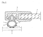
- FIG. 1 shows an embodiment of a sealing profile (1) for a cooling unit sliding cover of a refrigerator, not shown, in sectional view, consisting of a sealing bellows (2) and a sealing foot (3), wherein the foot part (3) for the purpose of fastening the sealing profile (1) in one Halteut the access opening to the refrigerator is used and thus snap-like manner or inserted into the receiving groove snaps.
- sealing strips (7) which are arranged at a distance from one another in the range between 0.1 to 5 mm, wherein the sealing strips (7) made of a polymeric material comprising polyethylene and / / or polyoxymethylene and / or polyamide and / or polypropylene and / or polyvinyl chloride - polytetrafluoroethylene mixture and / or a fluoropolymer and / or a fluoroethylene propylene polymer and / or polybutylene terephthalate (PBT) and / or polycarbonate (PC) and / or polycarbonate blends and / or polyethylene terephthalate (PET ) and / or impact-modified polymethyl methacrylate (PMMA) and / or polyphenylene oxide-styrene-butadiene and blends and / or polyphenylene oxide-polyamide blend (PPO-PA) exist and the be
- Laterally arranged hinge points (8) adapt the deformation of the sealing bellows (2) to the weight-related surface pressure generated by the sliding cover, wherein the elastic modulus of the bellows material is in the range between 1 and 400 N / mm 2 .
- the wall thickness (d1) of the sealing bellows is designed in the range between 0.2 to 5 mm and the wall thicknesses (d2) of the hinge points (8) in the range between 0.1 to 4.8 mm.
- the Shore hardness of the bellows material is in the range between Shore A 20 to Shore A 98, wherein the bellows material is made of a thermoplastic styrene-based polymer (TPE-S) and / or thermoplastic olefin-based polymer (TPE-O) and / or partially crosslinked or fully crosslinked thermoplastic elastomer olefin-based (TPE-V) and / or thermoplastic polyurethane-based elastomer (TPE-U) and / or thermoplastic polyetheramide-based elastomer (TPE-A) and / or thermoplastic polyetherester-based elastomer (TPE-E) and / or Soft polyvinyl chloride (PVC-P) exists.
- TPE-S thermoplastic styrene-based polymer
- TPE-O thermoplastic olefin-based polymer
- TPE-V thermoplastic polyurethane-based elastomer
- TPE-U thermo
- the upper side of the sealing foot (3) thus forms a hollow chamber in a form-fitting manner together with the sealing bellows (2) and the length component of the upper side of the sealing foot on the circumferential wall of the sealing bellows / hollow chamber comprises 5 to 80%.
- the sealing foot has laterally locking elements with retaining lugs (9) and consists entirely of a polymer material comprising polyoxymethylene and / or polyamide and / or acrylonitrile-styrene-acrylic ester copolymer and / or polyvinyl chloride and / or polypropylene and / or polyethylene and / or elastomer-modified polypropylene and / or acrylic-butadiene-styrene copolymer and / or styrene-butadiene copolymer and / or polybutylene terephthalate (PBT) and / or polycarbonate (PC) and / or polycarbonate blends and / or polyethylene terephthalate (PET) and / or toughened polymethyl methacrylate (PMMA) ) and / or polyphenylene oxide-styrene-butadiene and blends and / or polyphenylene oxide-polyamide blend (PPO-PA) and
- the polymer materials mentioned for the sealing strips according to the invention and the sealing foot can also comprise blends.
- the ratio (aspect ratio) base width to the height of the sealing strips (7) is in the range between 5 to 1 and 1 to 5.
- the sealing strips (7) can be arranged symmetrically and / or equidistantly.
- the distance of the sealing strips is in the range between 1.2 to 2 mm; Other distances are conceivable according to the invention.
- the surface of the sealing strips (7) is provided with a microstructure, whereby a reduction of the sliding resistance / the coefficient of friction can be achieved.
- the preparation of the seal according to the invention takes place in the coextrusion process.
- FIG. 2 shows the seal (1) according to the invention used in a refrigerator sliding cover of a refrigerator in Thomastdargna after FIG. 1 wherein the foot part (3) is snap-in / or insertable for the purpose of fastening the sealing profile (1) in a provided receiving / retaining groove of the bordering frame (5) with attached sliding lid glass (6) is installed.
- the sealing strips (7) are materially connected to the sealing bellows (2) and lie on a sliding guide (4) of the cooling device, not shown.
- a gasket assembly according to claims 1 to 9 showed the advantages resulting from the invention.
Landscapes
- Engineering & Computer Science (AREA)
- Civil Engineering (AREA)
- Structural Engineering (AREA)
- Mechanical Engineering (AREA)
- Combustion & Propulsion (AREA)
- Physics & Mathematics (AREA)
- Chemical & Material Sciences (AREA)
- Thermal Sciences (AREA)
- General Engineering & Computer Science (AREA)
- Compositions Of Macromolecular Compounds (AREA)
- Refrigerator Housings (AREA)
- Specific Sealing Or Ventilating Devices For Doors And Windows (AREA)
- Sealing Devices (AREA)
Description
- Die Erfindung betrifft ein Dichtungsprofil für einen Kühlgeräteschiebedeckel nach dem Oberbegriff des Anspruchs 1.
- Aus dem Stand der Technik ist bekannt, dass bei Kühlgeräten mit einem zu kühlenden Raumvolumen für die darin befindlichen Waren, Schiebdeckelanordnungen diesen Warenraum verschließen, wobei durch Gleitleisten übereinander verschiebbar geführte Schiebedeckel zum Verschließen des Warenraumes verwendet werden. Wesentlich ist , dass das Dichtungsprofil in Wirkverbindung mit einer Gleitleiste stehend eine möglichst gute Gleiteigenschaft gewährleistet und die zum Verschieben des Schiebedeckels notwendige Kraft so gering gehalten wird , dass bspw. ein Kunde das Öffnen und Schließen des Schiebedeckels als leichtgängig empfindet und geringe Beeinträchtigung durch das Öffnen/Schließen des Schiebedeckels erfährt.
- Weiterhin soll das Dichtprofil die Spaltbildung zwischen Deckel und Gleitführung/- leiste verhindern , die bspw. durch fertigungsbedingte Toleranzen und Abweichungen der Schiebedeckel oder der Gleitführungen/-leisten entstehen können. Durch die Spaltbildung findet bekanntermaßen ein Luftaustausch zwischen der Umgebung und dem Kühlraum statt , wobei wärmere Außenluft in den Kühlraum eintritt und energiedissipierend wirkt und somit den Wirkungsgrad des Kühlgerätes gesamthaft reduziert. Weiterhin wird eine zunehmende Vereisung des Kühlraums bewirkt. Insbesondere durch die hohe Nutzung der Schiebedeckelanordnung im täglichen Gebrauch von Kühltruhen in bspw. Supermärkten ist die Beachtung der Verschleißerscheinungen der Dichtprofile verbunden mit der gewünschten Leichtgängigkeit der Schiebedeckelanordnung wesentlich. Somit hat die Materialauswahl für die beiden aufeinander gleitenden Komponenten der Anordnung unter dem Gesichtspunkt der Verschleißminimierung zu erfolgen.
- Aus der
DE 196 22 590 A1 ist eine Schiebedeckeleinrichtung für Tiefkühltruhen oder dergleichen bekannt, wobei eine Abdeckeinheit mit einer Rahmenanordnung in Verbindung steht und diese Rahmenanordnung in einer Verschieberichtung beweglich ist und die elastische Dichteinheit lösbar an der Schiebedeckeleinrichtung befestigt wird. Vorzugsweise besteht die Dichteinheit aus Weichpolyvinylchlorid. - Nachteilig ist, dass durch diese Dichteinheit die zur Verschiebung des Deckels notwendige Kraft vergrößert wird. Dies resultiert daher, dass die Dichtungseinheit bei aufgesetzter Schiebedeckeleinrichtung seitlich drückend an einer Truhenkörperinnenseite vorgespannt anliegt. Somit tritt zur Gleitreibung eine zweite Kraftkomponente hinzu, die durch die elastische Vorspannung der Dichteinheit resultiert . Insbesondere wird die dichtende Wirkfunktion im geschlossenen Zustand während der Lebensdauer der Dichtung des Schiebedeckels abnehmen, da die Vorspannung der Dichteinheit durch materialbedingte Relaxationsvorgänge und Materialermüdung abnimmt, sodass die gesamte Dichtungsrahmeneinheit ausgewechselt werden muss. Gleiches bedingt die thermische Belastung der Dichtung in Verbindung mit dem mechanischen Abrieb, hervorgerufen durch die Öffnungs- und Schließvorgänge des Schiebedeckels.
- Studien ergaben, dass in stark frequentierten Supermärkten die Kühltheken mit Schiebedeckeleinrichtung im Mittel ca. 800-1300 mal pro Tag geöffnet und geschlossen werden. Dies zeigt, dass die Dichtungsmaterialien/-eigenschaften sowohl den mechanischen Belastungen, als auch den sich durch Öffnungs-/Schließvorgänge ergebenden Temperaturwechselbelastungen Stand halten müssen.
- Gerade beim Öffnungsvorgang wird sich die Temperatur der Dichtung durch den entstehenden Kontakt mit der nahezu auf Raumtemperatur befindlichen Gleitschiene erhöhen, sodass insbesondere die Gleitoberflächen der Dichtung dem Temperaturwechsellastspiel bei Benutzung der Schiebedeckelanordnung verstärkt ausgesetzt sind.
- In der
DE 201 01 616 U1 wird ein Anschlagdämpfungsprofil beschrieben mit einem Harpunensteg zum Einsetzen in eine Längsnut auf der Stirnkante einer Möbelkorpuswand und mit einem sich einstückig an den Harpunensteg anschließenden Quersteg, wobei Harpunensteg und Quersteg aus einem harten Kunststoff bestehen und der Quersteg von einem koextrudierten elastischen Dämpfungsbereich aus weichem Kunststoff überwölbt ist, der mit dem Quersteg einen Längskanal bildet. Bei der Verwendung des Anschlagdämpfungsprofils soll es nicht möglich sein, dass Weichmacher in die aufliegende Oberfläche wandert. Außerdem soll das Abheben der Tür beim Öffnen ohne ein störendes Schmatzgeräusch möglich sein. Realisiert soll es dadurch sein, dass der Dämpfungsbereich auf seiner Außenseite eine koextrudierte Anschlagrippe aus hartem Kunststoff aufweist. - In der
US 3,023,466 ist eine weitere gattungsgemäße Dichtung für die Tür von Kühlwagen beschrieben, die vier gerade Seitenteile aus hohlem, elastischem Dichtmaterial umfasst. Die Länge eines jeden Seitenteils entspricht der einer Seite eines Kühlwagentürrahmens, an den die Dichtung montiert werden soll. Das Dichtmaterial hat eine flache Unterseite und eine gewölbte Oberseite. An der Oberseite sind längs in Proofilrichtung verlaufende Rippen angeordnet. Die geraden Seitenteile sind so angeordnet, dass sie ein Rechteck definieren, dessen Größe der eines Autotürrahmens entspricht, an den die Dichtung montiert werden soll. Bogenförmige Dichtungseckteile werden fest mit den benachbarten Enden der geraden Dichtungsteilbereiche verbunden. Ein flaches, im Wesentlichen dreieckiges Befestigungselement erstreckt sich seitlich aus dem Umfang der Dichtung heraus nur an der gewölbten Seite eines jeden Eckteils und die entsprechenden geraden Außenkanten werden auf die geraden Außenkanten der geraden Dichtungsseitenteile ausgerichtet und verbinden sich mit diesen. Das Befestigungselement liegt normalerweise unterhalb der Dichtung und in unmittelbarer Nähe deren Unterseite, wobei die Dichtung im Verhältnis zur Klappe nach oben gebogen werden kann, so dass diese an einen darunterliegenden Rahmen genagelt werden kann. - In der
AT 005 408 U1 - Damit soll die Vereisungsgefahr infolge des Luftaustausches im Bereich der Gleitdichtung weitgehend vermieden werden , ohne die Verschiebebewegung des Schiebedeckels und dessen Leichtgängigkeit zu beeinflussen. Hierzu ist die leistenparallele Dichtlippe biegeelastisch ausgebildet , sodass Herstellungstoleranzen im Bereich der Gleitführung der Kühltruhe einfach auszugleichen sind und ein Luftspalt zwischen Dichtleiste/-lippe und Gleitführung vermieden wird.
- Dazu ist die Dichtlippe zwischen zwei Laufflächen bildende Randwülste der Dichtleisten angeordnet. Die Dichtung muss, damit eine Dichtwirkung des Deckels im eingebauten Zustand gewährleistet werden soll, eine ausreichende Vorspannung besitzen. Die damit verbundene Vergrößerung der Kontaktfläche zwischen Deckel und Gleitführung bewirkt somit eine Erhöhung des zum Verschieben/Bewegen des Deckels notwendigen Kraftaufwandes mit den vorgenannten Nachteilen. Auch bei dieser Anordnung sind Materialermüdungs- und -verschleißerscheinungen über die Zeitstandsdauer zu erwarten, die nachteilig auf die Dichteigenschaft der Dichtlippe wirken. Somit wird die Funktion des Dichtungsaufbaus für den Fall, dass die Dichtungslippe nicht mehr infolge des Materialverschleißes an der Oberfläche der Gleitfläche dichtend zum Anliegen kommt, nachteilig beeinflusst oder aufgehoben. Weiterhin bewirkt das Öffnen des Schiebedeckels, dass Warmluft über die Gleitführungen strömt und es aufgrund der Temperaturdifferenz zwischen einströmender Luft und den Gleitführungen zu einer Kondensation entlang der Gleitoberfläche der Führungen kommen kann. Dieses Kondensat bewirkt bei Temperaturerniedrigung in diesem Bereich ein Anfrieren der Dichtungslippe an der Gleitführung, sodass es bei nachfolgender Schiebedeckelbewegung zur Elongation der "festklebenden/- haftenden" Dichtlippe kommt. Hierbei können Dehnungskräfte im Bereich der Reißgrenze zu Rissen/Mikrorissen in der Dichtung oder in der Dichtungsoberfläche führen, welche die Dichtungseigenschaft der Dichtlippe herabsetzen bzw. Ausgangspunkt von Materialermüdungserscheinungen sind.
- Ausgehend vom Stand der Technik liegt der Erfindung die Aufgabe zugrunde, ein Dichtungsprofil für Kühlgeräteschiebedeckel zu schaffen und eine Profilform dafür anzugeben, so dass die genannten Nachteile aus dem Stand der Technik vermieden werden.
- Diese Aufgabe wird erfindungsgemäß durch ein Dichtungsprofil gemäß der im Anspruch 1 angegebenen Merkmalskombination gelöst.
- Vorteilhafte Weiterbildungen des Dichtungsprofils sind Gegenstand der Unteransprüche.
- Erfindungsgemäß wurde zunächst erkannt, dass für einen Schiebedeckel eines Kühl- oder Gefriergerätes, mit einem Dichtungsbalg und einem damit stoffschlüssig verbundenen Dichtungsfuß, welcher einen Einführabschnitt aufweist und mit seitlich gerichteten Haltenasen versehen ist, die zum Einrasten in Aufnahmenuten im Einfassrahmen vorgesehen sind, der Dichtungsbalg mit wulstförmigen Streifen entlang seiner Oberfläche, vorzugsweise in Profillängsrichtung, versehen werden kann, wobei der Abstand der Streifen zueinander im Bereich von 0,1 bis 5 mm liegt und die Streifen aus einem Polymermaterial umfassend Polyethylen und/oder Polyoximethylen und/oder Polyamid und/oder Polypropylen und/oder Polyvinylchlorid - Polytetrafluorethylengemisch und/oder einem Fluorpolymer und/oder einem Fluorethylenpropylenpolymer und/oder Polybutylenterephtahlat (PBT) und/oder Polycarbonat (PC) und/oder Polycarbonatblends und/oder Polyethylenterephtalat (PET) und/oder schlagzähmodifiziertes Polymethylmethacrylat (PMMA) und/oder Polyphenylenoxid-Styrol-Butadien und Blends und/oder Polyphenylenoxid-Polyamid-Blend (PPO-PA) bestehen und stoffschlüssig mit der Balgoberfläche verbunden sind. Weiterhin wurde erfindungsgemäß erkannt, dass der Dichtungsprofilbalg somit als elastisches Element wirkt und die Spaltbildung zwischen Schiebedeckel und Gleitführung verhindert, wobei seitlich angeordnete Gelenkstellen die Deformation des Dichtungsbalgs auf die durch den Schiebedeckel erzeugte Flächenpressung anpassen. Der Elastizitätsmodul des Dichtungsbalgmaterials liegt vorzugsweise im Bereich zwischen 1 bis 400 N/mm2, wobei die Shorehärte des Dichtungsbalgmaterials im Bereich zwischen Shore A 20 bis Shore A 98 liegt; die Wandstärke des Dichtungsbalgs im Bereich zwischen 0,2 bis 5 mm ausgelegt ist und die Wandstärke der Gelenkstellen im Bereich zwischen 0,1 bis 4,8 mm liegen.
- Zur Ausbildung des Dichtungsbalgs haben sich als besonders geeignet die Materialien thermoplastisches Polymer auf Styrolbasis (TPE-S) und/oder thermoplastisches Polymer auf Olefinbasis (TPE-O) und/oder teilvernetztes oder vollvernetztes thermoplastisches Elastomer auf Olefinbasis (TPE-V) und/oder thermoplastisches Elastomer auf Polyurethanbasis (TPE-U) und/oder thermoplastisches Elastomer auf Polyetheramid-Basis (TPE-A) und/oder thermoplastisches Elastomer auf Polyetherester-Basis (TPE-E) und/oder Weich-Polyvinylchlorid (PVC-P) erwiesen. Die Oberseite des Dichtungsfußes bildet dabei zusammen mit dem Dichtungsbalg formschlüssig eine Hohlkammer und der Längenanteil der Dichtungsfußoberseite (siehe
Figur 1 ) an der umlaufenden Wand des Dichtungsbalgs/Hohlkammer umfasst 5 bis 80%, wobei der Dichtungsfuß Verrastelemente mit Haltenasen seitlich angeordnet aufweist, gesamthaft bestehend aus einem Polymermaterial umfassend ein Polyoximethylen und/oder ein Polyamid und/oder ein Acrylnitril-Styrol-Acrylester-Copolymer und/oder ein Polyvinylchlorid und/oder ein Polypropylen und/oder ein Polyethylen und/oder ein elastomermodifiziertes Polypropylen und/oder ein Acryl-Butadien-Styrol-Copolymer und/oder ein Styrol-Butadien-Copolymer und/oder Polybutylenterephtahlat (PBT) und/oder Polycarbonat (PC) und/oder Polycarbonatblends und/oder Polyethylenterephtalat (PET) und/oder schlagzähmodifiziertes Polymethylmethacrylat (PMMA) und/oder Polyphenylenoxid-Styrol-Butadien und Blends und/oder Polyphenylenoxid-Polyamid-Blend (PPO-PA) und/oder thermoplastisches Elastomer. - Erfindungsgemäß wurde erkannt, dass gemäß der Merkmale -c-, -I- und -o- nach Anspruch 1 auch vorteilhafte Materialmischungen für die Dichtprofilstreifen nach Anspruch 1-c-, den Dichtungsbalg nach Anspruch 1-l- und den Dichtungsfuß nach Anspruch 1-o- verwendbar sind, sowie Blends aus den genannten Polymermaterialien.
- Gemäß der Erfindung ist weiterhin die geometrische Auslegung der mit der Balgoberfläche stoffschlüssig verbundenen Streifen mit Blick auf die auftretenden Reibungskräfte zwischen Dichtung und Gleitführung am Kühl-/Gefriergerätekorpus und dem aufliegenden Schiebedeckel wesentlich.
- Gerade die starke Gewichtsbelastung der Schiebedeckelanordnung bedingt bekanntlich die hohen Reibungskräfte an der Dichtung, die den Materialverschleiß und auftretende Materialermüdung hervorrufen.
- In diesem Zusammenhang wurde erkannt, dass zur Reduzierung des Verschleißverhaltens und der wirkenden Reibungskräfte Streifen so auf der Dichtungsbalgoberfläche angebracht sind, dass das Verhältnis (Aspektverhältnis) der Basisbreite zur Höhe der Dichtungsstreifen im Bereich zwischen 5 zu 1 und 1 zu 5 liegt.
- Alternativ können die Dichtungsstreifen der Balgoberfläche symmetrisch und/oder äquidistant entlang der Gleitverlaufrichtung angeordnet sein, wodurch die optimale Gewichtskraftverteilung des Schiebedeckels auf das Dichtungsprofil gewährleistet wird; dies schränkt aber die Erfindung nicht ein.
- Ein Abstand der Dichtungsstreifen entlang der Balgoberfläche zueinander nach Anspruch 4 gewährleistet eine gute Dichtwirkung des Dichtungsprofils.
- Weiterhin wurde erfindungsgemäß erkannt, dass die Streifen, die aus einem tribologisch optimierten "härterem" Material bestehen so ausgelegt sind, dass im Zusammenwirken mit dem Dichtungsbalg ein durch die Flächenpressung des Schiebedeckels deformierbare Dichtungsanordnung geschaffen wird, die ein verbessertes elastisches und/oder quasielastisches Rückstellvermögen aufweist.
- Hierbei kommt es somit zu einer Gewichtskraftverlagerung entlang der Oberflächennormalen des Dichtungsprofils, wobei der Dichtungsfuß in quasielastischer stoffschlüssiger Wirkverbindung mit dem Dichtungsbalg steht.
- Ein Dichtungsprofil nach Anspruch 1 mit einer Gleitführung bestehend aus einem Polytetrafluorethylen-Polyvinylchlorid-Gemisch bewirkt, dass die Reibungszahl einer Schiebedeckelanordnung im Bereich zwischen 0,1 bis 0,2 liegt.
- Eine zusätzliche Mikrostruktur nach Anspruch 6 entlang der Oberfläche der Profildichtungsstreifen bewirkt eine vorteilhafte weitere Reduktion des Gleitwiderstandes/der Reibungszahl auf Werte gemäß Anspruch 7 für eine Schiebdeckelanordnung. In einer bevorzugten Ausführungsform sind die Profildichtungsstreifen entlang des verwendeten Öffnungsbereich eines Schiebedeckels nur partiell mit einer gleitfähigen Mikrostruktur versehen.
- Durchgeführte Versuche mit Schiebedeckelanordnungen und dem erfindungsgemäßen Dichtungsprofil nach Anspruch 1 zeigten, dass die Schallemission während des Gleitvorgangs beim Öffnen oder Schließen des Schiebedeckels von Kühl-/Gefriergeräten vorteilhaft im Frequenzbereich von 30 Hz bis 16 kHz um Werte zwischen 2 bis 10 dB gedämpft wurden. Die Erfindung geht dabei von der Erkenntnis aus, dass die akustische Entkopplung durch den Dichtungsstreifen bestehend aus dem Material nach Anspruch 1 -c- , dem Dichtungsbalg bestehend aus dem Material nach Anspruch 1 -l- und der Schiebedeckelgleitfläche im Einfassrahmen erfolgt und eine Schalldämpfung im vorgenannten Frequenzbereich bewirkt. Auch höhere Schalldämpfungswerte sind mit der Erfindung möglich.
- Eine weitere Aufgabe der Erfindung ist es, eine Dichtungsrahmenanordnung nach einem der Ansprüche 1 bis 9 anzugeben.
- Ein Ausführungsbeispiel der Erfindung wird nachfolgend anhand der Zeichnungen näher erläutert, wobei der Schutzumfang der Erfindung nicht beschränkend verstanden werden soll.
- In dieser zeigen:
- Fig. 1
- schematisch ein erfindungsgemäßes Dichtungsprofil im Schnitt
- Fig. 2
- schematisch ein Dichtungsprofil eingebaut in einen Schiebedeckel für ein Kühlgerät
-
Figur 1 zeigt eine Ausführungsform eines Dichtungsprofils (1) für einen nicht dargestellten Kühlgeräteschiebedeckel eines Kühlgerätes in Schnittansicht, bestehend aus einem Dichtungsbalg (2) und einem Dichtungsfuß (3) , wobei der Fußteil (3) zum Zwecke der Befestigung des Dichtungsprofils (1) in einer vorgesehenen Haltenut der Zugangsöffnung zum Kühlgerät dient und damit schnappverschlußartig oder einschiebbar in die Aufnahmenut einrastet. - In der gezeigten Darstellung befinden sich an der Dichtungsbalgoberfläche (2) längsverlaufend angeordnete wulstförmige Dichtungsstreifen (7), die in einem Abstand zueinander im Bereich zwischen 0,1 bis 5 mm angeordnet sind, wobei die Dichtungsstreifen (7) aus einem Polymermaterial umfassend Polyethylen und/oder Polyoximethylen und/oder Polyamid und/oder Polypropylen und/oder Polyvinylchlorid - Polytetrafluorethylengemisch und/oder einem Fluorpolymer und/oder einem Fluorethylenpropylenpolymer und/oder Polybutylenterephtahlat (PBT) und/oder Polycarbonat (PC) und/oder Polycarbonatblends und/oder Polyethylenterephtalat (PET) und/oder schlagzähmodifiziertem Polymethylmethacrylat (PMMA) und/oder Polyphenylenoxid-Styrol-Butadien und Blends und/oder Polyphenylenoxid-Polyamid-Blend (PPO-PA) bestehen und die wulstförmigen Dichtungsstreifen stoffschlüssig mit der Dichtungsbalgoberfläche (2) verbunden sind. Der Dichtungsprofilbalg (2) wirkt als elastisches Element und verhindert somit eine Spaltbildung zwischen dem Schiebedeckel und der Gleitführung (4) (siehe
Figur 2 ). - Seitlich angeordnete Gelenkstellen (8) passen die Deformation des Dichtungsbalgs (2) auf die durch den Schiebedeckel erzeugte gewichtsbedingte Flächenpressung an, wobei der Elastizitätsmodul des Dichtungsbalgmaterials im Bereich zwischen 1 bis 400 N/mm2 liegt. Die Wandstärke (d1) des Dichtungsbalgs ist im Bereich zwischen 0,2 bis 5 mm ausgelegt und die Wandstärken (d2) der Gelenkstellen (8) im Bereich zwischen 0,1 bis 4,8 mm.
- Die Shorehärte des Dichtungsbalgmaterials liegt im Bereich zwischen Shore A 20 bis Shore A 98, wobei das Dichtungsbalgmaterial aus einem thermoplastischen Polymer auf Styrolbasis (TPE-S) und/oder thermoplastischem Polymer auf Olefinbasis (TPE-O) und/oder teilvernetztem oder vollvernetztem thermoplastischem Elastomer auf Olefinbasis (TPE-V) und/oder thermoplastischem Elastomer auf Polyurethanbasis (TPE-U) und/oder thermoplastisches Elastomer auf Polyetheramid-Basis (TPE-A) und/oder thermoplastisches Elastomer auf Polyetherester-Basis (TPE-E) und/oder Weich-Polyvinylchlorid (PVC-P) besteht.
- Die Oberseite des Dichtungsfußes (3) bildet somit zusammen mit dem Dichtungsbalg (2) formschlüssig eine Hohlkammer und der Längenanteil der Dichtungsfußoberseite an der umlaufenden Wand des Dichtungsbalgs/Hohlkammer umfasst 5 bis 80%.
- Der Dichtungsfuß weist seitlich Verrastelemente mit Haltenasen (9) auf und besteht gesamthaft aus einem Polymermaterial umfassend Polyoximethylen und/oder Polyamid und/oder Acrylnitril-Styrol-Acrylester-Copolymer und/oder Polyvinylchlorid und/oder Polypropylen und/oder Polyethylen und/oder elastomermodifiziertes Polypropylen und/oder Acryl-Butadien-Styrol-Copolymer und/oder Styrol-Butadien-Copolymer und/oder Polybutylenterephtahlat (PBT) und/oder Polycarbonat (PC) und/oder Polycarbonatblends und/oder Polyethylenterephtalat (PET) und/oder schlagzähmodifiziertes Polymethylmethacrylat (PMMA) und/oder Polyphenylenoxid-Styrol-Butadien und Blends und/oder Polyphenylenoxid-Polyamid-Blend (PPO-PA) und/oder thermoplastisches Elastomer.
- Die genannten Polymermaterialien für die erfindungsgemäßen Dichtungsstreifen und den Dichtungsfuß können auch Blends umfassen.
- Das Verhältnis (Aspektverhältnis) Basisbreite zur Höhe der Dichtungsstreifen (7) liegt im Bereich zwischen 5 zu 1 und 1 zu 5.
- In einer weiteren, nicht dargestellten Ausführungsform, können die Dichtungsstreifen (7) symmetrisch und/oder äquidistant angeordnet sein. Der Abstand der Dichtungsstreifen liegt im Bereich zwischen 1,2 bis 2 mm; andere Abstände sind erfindungsgemäß denkbar.
- In einer weiteren Ausführungsform ist die Oberfläche der Dichtungsstreifen (7) mit einer Mikrostruktur versehen, wodurch eine Reduktion des Gleitwiderstandes/der Reibungszahl erreicht werden kann.
- Die Herstellung der erfindungsgemäßen Dichtung erfolgt im Koextrusionsverfahren.
-
Figur 2 zeigt die erfindungsgemäße Dichtung (1) eingesetzt in einen Kühlgeräteschiebedeckel eines Kühlgerätes in Schnitttdarstellung nachFigur 1 , wobei das Fußteil (3) schnappverschlußartig/oder einschiebbar zum Zwecke der Befestigung des Dichtungsprofils (1) in einer vorgesehenen Aufnahme-/Haltenut des Einfassrahmens (5) mit daran befestigtem Schiebedeckelglas (6) verbaut ist. Die Dichtungsstreifen (7) sind stoffschlüssig mit dem Dichtungsbalg (2) verbunden und liegen auf einer Gleitführung (4) des nicht weiter dargestellten Kühlgerätes auf. - Durchgeführte Schallemissionsuntersuchungen zeigten, dass die bei sonst üblichen Schiebedeckeln entstehenden Geräusche im Frequenzbereich von 30 Hz bis 16 kHz, hervorgerufen durch das Verschieben des Schiebedeckels entlang der Gleitführung (4) in Verschieberichtung, durch die Materialwahl gemäß Anspruch 1-c- und 1-l- um Werte von 2 bis zu 10 dB gedämpft werden konnten.
- Eine Dichtungsrahmenanordnung nach den Ansprüchen 1 bis 9 zeigte die durch die Erfindung sich ergebenden Vorteile.
Claims (10)
- Dichtung für einen Schiebedeckel eines Kühl- oder Gefriergerätes, mit einem Dichtungsbalg und einem damit stoffschlüssig verbundenen Dichtungsfuß, welcher einen Einführabschnitt aufweist und mit seitlich gerichteten Haltenasen versehen ist, die zum Einrasten in Aufnahmenuten im Einfassrahmen vorgesehen sind, wobei- a- der Dichtungsbalg (2) mit wulstförmigen Streifen (7) entlang seiner Oberfläche versehen ist und- b- die wulstförmigen Streifen (7) stoffschlüssig mit der Balgoberfläche (2) verbunden sind, wobei- c - der Dichtungsprofilbalg (2) als elastisches Element wirkt und- d- das elastische Element die Spaltbildung verhindert, wobei- e- seitlich angeordnete Gelenkstellen (8) die Deformation des Dichtungsprofilbalgs (2) auf die durch den Schiebedeckel erzeugte Flächenpressung anpassen und- f- die Shorehärte des Dichtungsbalgmaterials im Bereich zwischen Shore A 20 bis Shore A 98 liegt und- g- die Oberseite des Dichtungsfußteils (3) zusammen mit dem Dichtungsbalg (2) formschlüssig eine Hohlkammer bildet, wobei- h- der Längenanteil der Dichtungsfußoberseite an der umlaufenden Wand des Dichtungsbalgs/Hohlkammer (2) 5 bis 80% umfasst und- i- der Dichtungsfuß (3) Verrastelemente mit Haltenasen (9) seitlich angeordnet aufweist, bestehend aus einem Polymermaterial umfassend Polyoximethylen und/oder Polyamid und/oder Acrylnitril-Styrol-Acryl-ester-Copolymer und/oder Polyvinylchlorid und/oder Polypropylen und/oder Polyethylen und/oder elastomermodifiziertes Polypropylen und/oder Acryl-Butadien-Styrol-Copolymer und/oder Styrol-Butadien-Copolymer und/oder Polybutylenterephtahlat (PBT) und/oder Polycarbonat (PC) und/oder Polycarbonatblends und/oder Polyethylenterephtalat (PET) und/oder schlagzähmodifiziertes Polymethylmethacrylat (PMMA) und/oder Polyphenylenoxid-Styrol-Butadien und Blends und/oder Polyphenylenoxid-Polyamid-Blend (PPO-PA) und/oder thermoplastisches Elastomer (TPE),- j- das Dichtungsbalgmaterial aus einem thermoplastichen Polymer auf Styrolbasis (TPE-S) und/oder thermoplastischen Polymer auf Olefinbasis (TPE-O) und/oder teilvernetztem oder vollvernetztem thermoplastischen Elastomer auf Olefinbasis (TPE-V) und/oder thermoplastischen Elastomer auf Polyurethanbasis (TPE-U) und/oder thermoplastischen Elastomer auf Polyetherester-Basis (TPE-E) und/oder Weich-Polyvinylchlorid (PVC-P) besteht.
gekennzeichnet durch die Kombination folgender Merkmal- k- der Abstand der Streifen zueinander im Bereich von 0,1 bis 5 mm liegt, wobei- l- die Streifen (7) aus einem Polymermaterial umfassend Polyethylen und/oder Polyoximethylen und/oder Polyamid und/oder Polypropylen und/oder Polyvinylchlorid - Polytetrafluorethylengemisch und/oder einem Fluorpolymer und/oder einem Fluorethylenpropylenpolymer und/oder Polybutylenterephtahlat (PBT) und/oder einem Polycarbonat (PC) und/oder Polycarbonatblend und/oder einem Polyethylenterephtalat (PET) und/oder einem schlagzähmodifiziertem Polymethylmethacrylat (PMMA) und/oder einem Polyphenylenoxid-Styrol-Butadien und Blends und/oder einem Polyphenylenoxid-Polyamid-Blend (PPO-PA) bestehen und- m- der Elastizitätsmodul des Dichtungsbalgmaterials im Bereich zwischen 1 bis 400 N/mm2 liegt, wobei- n- die Wandstärke (d1) des Dichtungsbalgs (2) im Bereich zwischen 0,2 bis 5 mm liegt und- o- die Wandstärke (d2) der Gelenkstellen (8) im Bereich zwischen 0,1 bis 4,8 mm liegt. - Dichtung für einen Schiebedeckel eines Kühl- oder Gefriergerätes nach Anspruch 1, dadurch gekennzeichnet, dass das Verhältnis Basisbreite zur Höhe der Streifen (7) im Bereich zwischen 5:1 und 1:5 liegt.
- Dichtung für einen Schiebedeckel eines Kühl- oder Gefriergerätes nach Anspruch 1 und 2, dadurch gekennzeichnet, dass die Streifen (7) im Wesentlichen symmetrisch und/oder äquidistant angeordnet sind.
- Dichtung für einen Schiebedeckel eines Kühl- oder Gefriergerätes nach Anspruch 1 bis 3, dadurch gekennzeichnet, dass der Abstand der Streifen (7) zueinander vorzugsweise im Bereich zwischen 1,2 bis 2 mm liegt.
- Dichtung für einen Schiebedeckel eines Kühl- oder Gefriergerätes nach Anspruch 1 bis 4, dadurch gekennzeichnet, dass die Reibungszahl eines Schiebedeckels, der mit einer Dichtung (1) nach Anspruch 1 versehen ist und auf Gleitführungen (4) aus einem Polytetrafluorethylen-Polyvinylchlorid-Gemisch gelagert ist, im Bereich zwischen 0,1 bis 0,2 liegt.
- Dichtung für einen Schiebedeckel eines Kühl- oder Gefriergerätes nach Anspruch 1 bis 5, dadurch gekennzeichnet, dass die Oberfläche der Streifen (7) mit einer Mikrostruktur versehen ist.
- Dichtung für einen Schiebedeckel eines Kühl- oder Gefriergerätes nach Anspruch 6, dadurch gekennzeichnet, dass die Mikrostruktur den Gleitwiderstand/Reibungszahl auf Werte im Bereich zwischen 0,05 bis 0,15 reduziert.
- Dichtung für einen Schiebedeckel eines Kühl- oder Gefriergerätes nach Anspruch 1 bis 7, dadurch gekennzeichnet, dass die Streifen (7) bestehend aus einem der Materialien nach Anspruch 1 -k- und der Dichtungsbalg (2) bestehend aus einem der Materialien nach Anspruch 1 -o- eine akustische Entkopplung zwischen der Gleitführung (4) und dem Einfassrahmen (5) bewirken.
- Dichtung für einen Schiebedeckel eines Kühl- oder Gefriergerätes nach Anspruch 8, dadurch gekennzeichnet, dass eine Dämpfung des Gleitgeräuschpegels zwischen 2 und 10 dB im Frequenzbereich von 30 Hz bis 16 kHz erreicht wird.
- Dichtungsrahmenanordnung für einen Schiebedeckel eines Kühl- oder Gefriergerätes mit einem dichtung nach einem oder mehreren der vorhergehenden Ansprüche 1 bis 9.
Applications Claiming Priority (2)
| Application Number | Priority Date | Filing Date | Title |
|---|---|---|---|
| DE20312327U DE20312327U1 (de) | 2003-08-09 | 2003-08-09 | Dichtungsprofil für einen Kühlgeräteschiebedeckel |
| PCT/EP2003/013608 WO2005015097A1 (de) | 2003-08-09 | 2003-12-03 | Dichtungsprofil für einen kühlgeräteschiebedeckel |
Publications (2)
| Publication Number | Publication Date |
|---|---|
| EP1651914A1 EP1651914A1 (de) | 2006-05-03 |
| EP1651914B1 true EP1651914B1 (de) | 2010-08-11 |
Family
ID=29265710
Family Applications (1)
| Application Number | Title | Priority Date | Filing Date |
|---|---|---|---|
| EP03789114A Expired - Lifetime EP1651914B1 (de) | 2003-08-09 | 2003-12-03 | Dichtungsprofil für einen kühlgeräteschiebedeckel |
Country Status (9)
| Country | Link |
|---|---|
| EP (1) | EP1651914B1 (de) |
| AT (2) | AT9452U1 (de) |
| AU (1) | AU2003293750A1 (de) |
| DE (2) | DE20312327U1 (de) |
| ES (1) | ES2349771T3 (de) |
| PT (1) | PT1651914E (de) |
| RU (1) | RU57880U1 (de) |
| UA (1) | UA16513U (de) |
| WO (1) | WO2005015097A1 (de) |
Families Citing this family (12)
| Publication number | Priority date | Publication date | Assignee | Title |
|---|---|---|---|---|
| DE102004050652A1 (de) * | 2004-10-18 | 2006-04-27 | Holger Forstner | Gleitdichtung für Fenster, Türen, Rolläden und dergleichen |
| FR2914957B1 (fr) * | 2007-04-13 | 2012-05-11 | Aircelle Sa | Joint notamment pour bord de deviation d'inverseur de poussee a grilles pour avion et support de joint associe |
| DE202008007706U1 (de) * | 2008-06-10 | 2009-10-22 | Rehau Ag + Co | Dichtungsprofil |
| US9580954B2 (en) | 2009-10-05 | 2017-02-28 | R Value, Inc. | Press fit storm window system |
| US10202796B2 (en) | 2009-10-05 | 2019-02-12 | R Value, Inc. | Press fit storm window system |
| IT1399564B1 (it) * | 2010-04-16 | 2013-04-19 | Metzeler Automotive Profile | Guarnizione di tenuta per un autoveicolo, e procedimento per la sua fabbricazione |
| DE102010061508A1 (de) * | 2010-12-22 | 2012-06-28 | Norsk Hydro Asa | Dichtung |
| EP2886802B1 (de) * | 2013-12-20 | 2019-04-10 | Safran Aero Boosters SA | Innenringdichtung der letzten Kompressorstufe eines axialen Turbotriebwerks |
| EP3243994B1 (de) * | 2016-05-09 | 2019-01-30 | R Value, Inc. | Einpress-fenster-sturmsystem |
| EP3708880A1 (de) * | 2019-03-12 | 2020-09-16 | Saint-Gobain Glass France | Dichtung für ein gleitelement |
| DE102021111784A1 (de) * | 2021-05-06 | 2022-11-10 | SCHÜCO International KG | Dichtungsprofil sowie Blendrahmen und Flügelrahmen |
| CN113091376B (zh) * | 2021-05-14 | 2023-01-24 | 北京惠远明珠科技有限公司 | 一种分区化管理的智能冷库 |
Citations (2)
| Publication number | Priority date | Publication date | Assignee | Title |
|---|---|---|---|---|
| US3023466A (en) * | 1958-04-14 | 1962-03-06 | Robert L Landis | Sealing gasket |
| US4255903A (en) * | 1979-07-18 | 1981-03-17 | Clarke Reynolds | Snap-together sealing gasket |
Family Cites Families (7)
| Publication number | Priority date | Publication date | Assignee | Title |
|---|---|---|---|---|
| US3685206A (en) * | 1970-09-28 | 1972-08-22 | Gerald Kessler | Low-friction abrasion-resistant plastic weatherstrip |
| US4860495A (en) * | 1987-12-23 | 1989-08-29 | Gerald Kessler | Low friction plastic weatherstrip |
| DE29509701U1 (de) | 1995-06-14 | 1995-08-24 | Sigmund Kunststoff Gmbh | Schiebedeckeleinrichtung für Tiefkühltruhen u.dgl. |
| US5581951A (en) * | 1995-07-13 | 1996-12-10 | Pennsylvania Rail Car Company | Rail car crown gasket |
| DE10043154A1 (de) * | 2000-08-31 | 2002-03-28 | Webasto Vehicle Sys Int Gmbh | Dichtungsprofil, insbesondere für eine Schiebedachdichtung |
| DE20101616U1 (de) * | 2001-01-31 | 2001-03-22 | Nehl & Co Kunststoff Kg | Anschlagdämpfungsprofil |
| AT5408U1 (de) | 2001-08-30 | 2002-06-25 | Austria Haustechnik Ag | Schiebedeckel für ein kühlgerät |
-
2003
- 2003-03-12 UA UAU200601217U patent/UA16513U/uk unknown
- 2003-08-09 DE DE20312327U patent/DE20312327U1/de not_active Expired - Lifetime
- 2003-12-03 AT AT0914803U patent/AT9452U1/de not_active IP Right Cessation
- 2003-12-03 WO PCT/EP2003/013608 patent/WO2005015097A1/de active Application Filing
- 2003-12-03 RU RU2006106918/22U patent/RU57880U1/ru not_active IP Right Cessation
- 2003-12-03 PT PT03789114T patent/PT1651914E/pt unknown
- 2003-12-03 DE DE50312982T patent/DE50312982D1/de not_active Expired - Lifetime
- 2003-12-03 AT AT03789114T patent/ATE477461T1/de active
- 2003-12-03 AU AU2003293750A patent/AU2003293750A1/en not_active Abandoned
- 2003-12-03 ES ES03789114T patent/ES2349771T3/es not_active Expired - Lifetime
- 2003-12-03 EP EP03789114A patent/EP1651914B1/de not_active Expired - Lifetime
Patent Citations (2)
| Publication number | Priority date | Publication date | Assignee | Title |
|---|---|---|---|---|
| US3023466A (en) * | 1958-04-14 | 1962-03-06 | Robert L Landis | Sealing gasket |
| US4255903A (en) * | 1979-07-18 | 1981-03-17 | Clarke Reynolds | Snap-together sealing gasket |
Also Published As
| Publication number | Publication date |
|---|---|
| WO2005015097A1 (de) | 2005-02-17 |
| RU57880U1 (ru) | 2006-10-27 |
| ES2349771T3 (es) | 2011-01-11 |
| AU2003293750A1 (en) | 2005-02-25 |
| AT9452U1 (de) | 2007-10-15 |
| EP1651914A1 (de) | 2006-05-03 |
| DE20312327U1 (de) | 2003-10-16 |
| DE50312982D1 (de) | 2010-09-23 |
| PT1651914E (pt) | 2010-10-28 |
| ATE477461T1 (de) | 2010-08-15 |
| UA16513U (en) | 2006-08-15 |
Similar Documents
| Publication | Publication Date | Title |
|---|---|---|
| EP1651914B1 (de) | Dichtungsprofil für einen kühlgeräteschiebedeckel | |
| EP1639303B1 (de) | Tür mit isolierverglasung und damit ausgestattetes haushalts gerät | |
| WO2008110231A1 (de) | Dichtungsprofil und dieses einbeziehende dichtungsanordnung | |
| WO2017108190A1 (de) | Profilanordnung, insbesondere für ein kühl- und/oder gefriergerät | |
| DE19843843C2 (de) | Fensterscheibe mit einem eine Spaltabdeckung umfassenden Profilstrang | |
| EP3394534A1 (de) | Kühl- und/oder gefriergerät | |
| DE102007009945A1 (de) | Anputzleiste für Blendrahmen | |
| DE10259924B4 (de) | Schiebetüranlage | |
| EP3545247B1 (de) | Profilanordnung, insbesondere für ein kühl- und/oder gefriergerät | |
| EP0758044A1 (de) | Mehrzweckdichtung | |
| EP2363567A2 (de) | Rahmen eines Kunststofffensters oder einer Kunststofftür sowie Mitteldichtung hierfür | |
| DE3733230C2 (de) | Fahrzeugfenster mit einer vertikal verschiebbaren Doppelscheibe, insbesondere für Autotüren | |
| EP3135962B1 (de) | Dichtelement | |
| DE102008006545B4 (de) | Verfahren zur Herstellung einer Dichtung, insbesondere für ein Kraftfahrzeug und eine solche Dichtung | |
| DE102017117020A1 (de) | Sektionaltorblatt und Sektionaltor mit Sektionaltorblatt | |
| DE102007008707A1 (de) | Kühlgerät | |
| EP3324141B1 (de) | Kühl- und/oder gefriergerät | |
| DE20280427U1 (de) | Dichtung | |
| EP1279791B1 (de) | Absenkbare Türdichtung | |
| EP3848550A2 (de) | Fenster mit einem lüftungskanal | |
| DE202015103304U1 (de) | Türbodendichtung mit Rollabdichtung | |
| DE202007006336U1 (de) | Dichtungsgehäuse und Dichtung mit seitlichen Dichtungsprofilen | |
| DE102006010029A1 (de) | Kühlgerätetür sowie Türdichtung für eine derartige Kühlgerätetür | |
| EP0635620B1 (de) | Profil mit offenem Querschnitt insbesondere für Rolläden | |
| DE102018000868A1 (de) | Fahrzeugtür mit höhenverstellbarer Fensterscheibe |
Legal Events
| Date | Code | Title | Description |
|---|---|---|---|
| PUAI | Public reference made under article 153(3) epc to a published international application that has entered the european phase |
Free format text: ORIGINAL CODE: 0009012 |
|
| 17P | Request for examination filed |
Effective date: 20060120 |
|
| AK | Designated contracting states |
Kind code of ref document: A1 Designated state(s): AT BE BG CH CY CZ DE DK EE ES FI FR GB GR HU IE IT LI LU MC NL PT RO SE SI SK TR |
|
| DAX | Request for extension of the european patent (deleted) | ||
| 17Q | First examination report despatched |
Effective date: 20080916 |
|
| GRAP | Despatch of communication of intention to grant a patent |
Free format text: ORIGINAL CODE: EPIDOSNIGR1 |
|
| GRAS | Grant fee paid |
Free format text: ORIGINAL CODE: EPIDOSNIGR3 |
|
| GRAA | (expected) grant |
Free format text: ORIGINAL CODE: 0009210 |
|
| AK | Designated contracting states |
Kind code of ref document: B1 Designated state(s): AT BE BG CH CY CZ DE DK EE ES FI FR GB GR HU IE IT LI LU MC NL PT RO SE SI SK TR |
|
| REG | Reference to a national code |
Ref country code: GB Ref legal event code: FG4D Free format text: NOT ENGLISH |
|
| REG | Reference to a national code |
Ref country code: CH Ref legal event code: EP |
|
| REG | Reference to a national code |
Ref country code: IE Ref legal event code: FG4D Free format text: LANGUAGE OF EP DOCUMENT: GERMAN |
|
| REF | Corresponds to: |
Ref document number: 50312982 Country of ref document: DE Date of ref document: 20100923 Kind code of ref document: P |
|
| REG | Reference to a national code |
Ref country code: NL Ref legal event code: VDEP Effective date: 20100811 |
|
| REG | Reference to a national code |
Ref country code: ES Ref legal event code: FG2A Effective date: 20101228 |
|
| PG25 | Lapsed in a contracting state [announced via postgrant information from national office to epo] |
Ref country code: FI Free format text: LAPSE BECAUSE OF FAILURE TO SUBMIT A TRANSLATION OF THE DESCRIPTION OR TO PAY THE FEE WITHIN THE PRESCRIBED TIME-LIMIT Effective date: 20100811 Ref country code: NL Free format text: LAPSE BECAUSE OF FAILURE TO SUBMIT A TRANSLATION OF THE DESCRIPTION OR TO PAY THE FEE WITHIN THE PRESCRIBED TIME-LIMIT Effective date: 20100811 |
|
| PG25 | Lapsed in a contracting state [announced via postgrant information from national office to epo] |
Ref country code: CY Free format text: LAPSE BECAUSE OF FAILURE TO SUBMIT A TRANSLATION OF THE DESCRIPTION OR TO PAY THE FEE WITHIN THE PRESCRIBED TIME-LIMIT Effective date: 20100811 Ref country code: SI Free format text: LAPSE BECAUSE OF FAILURE TO SUBMIT A TRANSLATION OF THE DESCRIPTION OR TO PAY THE FEE WITHIN THE PRESCRIBED TIME-LIMIT Effective date: 20100811 Ref country code: BG Free format text: LAPSE BECAUSE OF FAILURE TO SUBMIT A TRANSLATION OF THE DESCRIPTION OR TO PAY THE FEE WITHIN THE PRESCRIBED TIME-LIMIT Effective date: 20101111 |
|
| REG | Reference to a national code |
Ref country code: IE Ref legal event code: FD4D |
|
| PG25 | Lapsed in a contracting state [announced via postgrant information from national office to epo] |
Ref country code: GR Free format text: LAPSE BECAUSE OF FAILURE TO SUBMIT A TRANSLATION OF THE DESCRIPTION OR TO PAY THE FEE WITHIN THE PRESCRIBED TIME-LIMIT Effective date: 20101112 Ref country code: SE Free format text: LAPSE BECAUSE OF FAILURE TO SUBMIT A TRANSLATION OF THE DESCRIPTION OR TO PAY THE FEE WITHIN THE PRESCRIBED TIME-LIMIT Effective date: 20100811 |
|
| PG25 | Lapsed in a contracting state [announced via postgrant information from national office to epo] |
Ref country code: IE Free format text: LAPSE BECAUSE OF FAILURE TO SUBMIT A TRANSLATION OF THE DESCRIPTION OR TO PAY THE FEE WITHIN THE PRESCRIBED TIME-LIMIT Effective date: 20100811 Ref country code: DK Free format text: LAPSE BECAUSE OF FAILURE TO SUBMIT A TRANSLATION OF THE DESCRIPTION OR TO PAY THE FEE WITHIN THE PRESCRIBED TIME-LIMIT Effective date: 20100811 |
|
| PG25 | Lapsed in a contracting state [announced via postgrant information from national office to epo] |
Ref country code: CZ Free format text: LAPSE BECAUSE OF FAILURE TO SUBMIT A TRANSLATION OF THE DESCRIPTION OR TO PAY THE FEE WITHIN THE PRESCRIBED TIME-LIMIT Effective date: 20100811 Ref country code: EE Free format text: LAPSE BECAUSE OF FAILURE TO SUBMIT A TRANSLATION OF THE DESCRIPTION OR TO PAY THE FEE WITHIN THE PRESCRIBED TIME-LIMIT Effective date: 20100811 Ref country code: RO Free format text: LAPSE BECAUSE OF FAILURE TO SUBMIT A TRANSLATION OF THE DESCRIPTION OR TO PAY THE FEE WITHIN THE PRESCRIBED TIME-LIMIT Effective date: 20100811 Ref country code: SK Free format text: LAPSE BECAUSE OF FAILURE TO SUBMIT A TRANSLATION OF THE DESCRIPTION OR TO PAY THE FEE WITHIN THE PRESCRIBED TIME-LIMIT Effective date: 20100811 |
|
| PLBE | No opposition filed within time limit |
Free format text: ORIGINAL CODE: 0009261 |
|
| STAA | Information on the status of an ep patent application or granted ep patent |
Free format text: STATUS: NO OPPOSITION FILED WITHIN TIME LIMIT |
|
| BERE | Be: lapsed |
Owner name: REHAU A.G. + CO Effective date: 20101231 |
|
| 26N | No opposition filed |
Effective date: 20110512 |
|
| PG25 | Lapsed in a contracting state [announced via postgrant information from national office to epo] |
Ref country code: MC Free format text: LAPSE BECAUSE OF NON-PAYMENT OF DUE FEES Effective date: 20101231 |
|
| REG | Reference to a national code |
Ref country code: CH Ref legal event code: PL |
|
| GBPC | Gb: european patent ceased through non-payment of renewal fee |
Effective date: 20101203 |
|
| REG | Reference to a national code |
Ref country code: DE Ref legal event code: R097 Ref document number: 50312982 Country of ref document: DE Effective date: 20110512 |
|
| PG25 | Lapsed in a contracting state [announced via postgrant information from national office to epo] |
Ref country code: BE Free format text: LAPSE BECAUSE OF NON-PAYMENT OF DUE FEES Effective date: 20101231 |
|
| PG25 | Lapsed in a contracting state [announced via postgrant information from national office to epo] |
Ref country code: LI Free format text: LAPSE BECAUSE OF NON-PAYMENT OF DUE FEES Effective date: 20101231 Ref country code: CH Free format text: LAPSE BECAUSE OF NON-PAYMENT OF DUE FEES Effective date: 20101231 |
|
| PG25 | Lapsed in a contracting state [announced via postgrant information from national office to epo] |
Ref country code: GB Free format text: LAPSE BECAUSE OF NON-PAYMENT OF DUE FEES Effective date: 20101203 |
|
| PG25 | Lapsed in a contracting state [announced via postgrant information from national office to epo] |
Ref country code: LU Free format text: LAPSE BECAUSE OF NON-PAYMENT OF DUE FEES Effective date: 20101203 Ref country code: HU Free format text: LAPSE BECAUSE OF FAILURE TO SUBMIT A TRANSLATION OF THE DESCRIPTION OR TO PAY THE FEE WITHIN THE PRESCRIBED TIME-LIMIT Effective date: 20110212 |
|
| PGFP | Annual fee paid to national office [announced via postgrant information from national office to epo] |
Ref country code: FR Payment date: 20121204 Year of fee payment: 10 |
|
| PGFP | Annual fee paid to national office [announced via postgrant information from national office to epo] |
Ref country code: PT Payment date: 20120604 Year of fee payment: 10 |
|
| REG | Reference to a national code |
Ref country code: PT Ref legal event code: MM4A Free format text: LAPSE DUE TO NON-PAYMENT OF FEES Effective date: 20140603 |
|
| PG25 | Lapsed in a contracting state [announced via postgrant information from national office to epo] |
Ref country code: PT Free format text: LAPSE BECAUSE OF NON-PAYMENT OF DUE FEES Effective date: 20140603 |
|
| REG | Reference to a national code |
Ref country code: FR Ref legal event code: ST Effective date: 20140829 |
|
| PG25 | Lapsed in a contracting state [announced via postgrant information from national office to epo] |
Ref country code: FR Free format text: LAPSE BECAUSE OF NON-PAYMENT OF DUE FEES Effective date: 20131231 |
|
| PGFP | Annual fee paid to national office [announced via postgrant information from national office to epo] |
Ref country code: ES Payment date: 20161216 Year of fee payment: 14 |
|
| REG | Reference to a national code |
Ref country code: ES Ref legal event code: FD2A Effective date: 20190702 |
|
| PG25 | Lapsed in a contracting state [announced via postgrant information from national office to epo] |
Ref country code: ES Free format text: LAPSE BECAUSE OF NON-PAYMENT OF DUE FEES Effective date: 20171204 |
|
| REG | Reference to a national code |
Ref country code: DE Ref legal event code: R081 Ref document number: 50312982 Country of ref document: DE Owner name: REHAU INDUSTRIES SE & CO. KG, DE Free format text: FORMER OWNER: REHAU AG + CO, 95111 REHAU, DE |
|
| REG | Reference to a national code |
Ref country code: AT Ref legal event code: PC Ref document number: 477461 Country of ref document: AT Kind code of ref document: T Owner name: REHAU INDUSTRIES SE & CO. KG, DE Effective date: 20220419 |
|
| PGFP | Annual fee paid to national office [announced via postgrant information from national office to epo] |
Ref country code: TR Payment date: 20221123 Year of fee payment: 20 Ref country code: DE Payment date: 20220610 Year of fee payment: 20 Ref country code: AT Payment date: 20221202 Year of fee payment: 20 |
|
| PGFP | Annual fee paid to national office [announced via postgrant information from national office to epo] |
Ref country code: IT Payment date: 20221229 Year of fee payment: 20 |
|
| REG | Reference to a national code |
Ref country code: DE Ref legal event code: R071 Ref document number: 50312982 Country of ref document: DE |
|
| REG | Reference to a national code |
Ref country code: AT Ref legal event code: MK07 Ref document number: 477461 Country of ref document: AT Kind code of ref document: T Effective date: 20231203 |