EP1651439B1 - Vorrichtung zum schrittweisen laminieren von multilayern - Google Patents
Vorrichtung zum schrittweisen laminieren von multilayern Download PDFInfo
- Publication number
- EP1651439B1 EP1651439B1 EP04738784A EP04738784A EP1651439B1 EP 1651439 B1 EP1651439 B1 EP 1651439B1 EP 04738784 A EP04738784 A EP 04738784A EP 04738784 A EP04738784 A EP 04738784A EP 1651439 B1 EP1651439 B1 EP 1651439B1
- Authority
- EP
- European Patent Office
- Prior art keywords
- lamination
- devices
- conveying direction
- press
- pressing
- Prior art date
- Legal status (The legal status is an assumption and is not a legal conclusion. Google has not performed a legal analysis and makes no representation as to the accuracy of the status listed.)
- Expired - Lifetime
Links
- 238000003475 lamination Methods 0.000 title claims abstract description 31
- 238000004804 winding Methods 0.000 claims description 7
- 238000001816 cooling Methods 0.000 claims description 4
- 238000010438 heat treatment Methods 0.000 claims description 4
- 239000002985 plastic film Substances 0.000 abstract description 24
- 229920006255 plastic film Polymers 0.000 abstract description 24
- 238000010030 laminating Methods 0.000 abstract description 17
- 238000006073 displacement reaction Methods 0.000 abstract 3
- 238000005096 rolling process Methods 0.000 abstract 2
- 238000003825 pressing Methods 0.000 description 62
- 239000000463 material Substances 0.000 description 14
- 229910052751 metal Inorganic materials 0.000 description 14
- 239000002184 metal Substances 0.000 description 14
- 239000011888 foil Substances 0.000 description 11
- 239000002131 composite material Substances 0.000 description 8
- 238000002844 melting Methods 0.000 description 5
- 230000008018 melting Effects 0.000 description 5
- RYGMFSIKBFXOCR-UHFFFAOYSA-N Copper Chemical compound [Cu] RYGMFSIKBFXOCR-UHFFFAOYSA-N 0.000 description 3
- 229910052802 copper Inorganic materials 0.000 description 3
- 239000010949 copper Substances 0.000 description 3
- 238000000034 method Methods 0.000 description 3
- 239000004033 plastic Substances 0.000 description 3
- 239000011347 resin Substances 0.000 description 3
- 229920005989 resin Polymers 0.000 description 3
- 229910052782 aluminium Inorganic materials 0.000 description 2
- XAGFODPZIPBFFR-UHFFFAOYSA-N aluminium Chemical compound [Al] XAGFODPZIPBFFR-UHFFFAOYSA-N 0.000 description 2
- 238000004140 cleaning Methods 0.000 description 2
- 239000004020 conductor Substances 0.000 description 2
- 238000011109 contamination Methods 0.000 description 2
- 239000002245 particle Substances 0.000 description 2
- 229920000728 polyester Polymers 0.000 description 2
- 239000000853 adhesive Substances 0.000 description 1
- 238000004026 adhesive bonding Methods 0.000 description 1
- 230000001070 adhesive effect Effects 0.000 description 1
- 238000005520 cutting process Methods 0.000 description 1
- 238000005530 etching Methods 0.000 description 1
- 239000004744 fabric Substances 0.000 description 1
- 239000003365 glass fiber Substances 0.000 description 1
- 239000000155 melt Substances 0.000 description 1
- 230000001737 promoting effect Effects 0.000 description 1
- 230000000630 rising effect Effects 0.000 description 1
- 230000002277 temperature effect Effects 0.000 description 1
Images


Classifications
-
- B—PERFORMING OPERATIONS; TRANSPORTING
- B32—LAYERED PRODUCTS
- B32B—LAYERED PRODUCTS, i.e. PRODUCTS BUILT-UP OF STRATA OF FLAT OR NON-FLAT, e.g. CELLULAR OR HONEYCOMB, FORM
- B32B15/00—Layered products comprising a layer of metal
- B32B15/04—Layered products comprising a layer of metal comprising metal as the main or only constituent of a layer, which is next to another layer of the same or of a different material
- B32B15/08—Layered products comprising a layer of metal comprising metal as the main or only constituent of a layer, which is next to another layer of the same or of a different material of synthetic resin
-
- B—PERFORMING OPERATIONS; TRANSPORTING
- B32—LAYERED PRODUCTS
- B32B—LAYERED PRODUCTS, i.e. PRODUCTS BUILT-UP OF STRATA OF FLAT OR NON-FLAT, e.g. CELLULAR OR HONEYCOMB, FORM
- B32B37/00—Methods or apparatus for laminating, e.g. by curing or by ultrasonic bonding
- B32B37/02—Methods or apparatus for laminating, e.g. by curing or by ultrasonic bonding characterised by a sequence of laminating steps, e.g. by adding new layers at consecutive laminating stations
-
- B—PERFORMING OPERATIONS; TRANSPORTING
- B32—LAYERED PRODUCTS
- B32B—LAYERED PRODUCTS, i.e. PRODUCTS BUILT-UP OF STRATA OF FLAT OR NON-FLAT, e.g. CELLULAR OR HONEYCOMB, FORM
- B32B15/00—Layered products comprising a layer of metal
- B32B15/04—Layered products comprising a layer of metal comprising metal as the main or only constituent of a layer, which is next to another layer of the same or of a different material
- B32B15/08—Layered products comprising a layer of metal comprising metal as the main or only constituent of a layer, which is next to another layer of the same or of a different material of synthetic resin
- B32B15/09—Layered products comprising a layer of metal comprising metal as the main or only constituent of a layer, which is next to another layer of the same or of a different material of synthetic resin comprising polyesters
-
- B—PERFORMING OPERATIONS; TRANSPORTING
- B32—LAYERED PRODUCTS
- B32B—LAYERED PRODUCTS, i.e. PRODUCTS BUILT-UP OF STRATA OF FLAT OR NON-FLAT, e.g. CELLULAR OR HONEYCOMB, FORM
- B32B15/00—Layered products comprising a layer of metal
- B32B15/14—Layered products comprising a layer of metal next to a fibrous or filamentary layer
-
- B—PERFORMING OPERATIONS; TRANSPORTING
- B32—LAYERED PRODUCTS
- B32B—LAYERED PRODUCTS, i.e. PRODUCTS BUILT-UP OF STRATA OF FLAT OR NON-FLAT, e.g. CELLULAR OR HONEYCOMB, FORM
- B32B15/00—Layered products comprising a layer of metal
- B32B15/20—Layered products comprising a layer of metal comprising aluminium or copper
-
- B—PERFORMING OPERATIONS; TRANSPORTING
- B32—LAYERED PRODUCTS
- B32B—LAYERED PRODUCTS, i.e. PRODUCTS BUILT-UP OF STRATA OF FLAT OR NON-FLAT, e.g. CELLULAR OR HONEYCOMB, FORM
- B32B17/00—Layered products essentially comprising sheet glass, or glass, slag, or like fibres
- B32B17/02—Layered products essentially comprising sheet glass, or glass, slag, or like fibres in the form of fibres or filaments
- B32B17/04—Layered products essentially comprising sheet glass, or glass, slag, or like fibres in the form of fibres or filaments bonded with or embedded in a plastic substance
-
- B—PERFORMING OPERATIONS; TRANSPORTING
- B32—LAYERED PRODUCTS
- B32B—LAYERED PRODUCTS, i.e. PRODUCTS BUILT-UP OF STRATA OF FLAT OR NON-FLAT, e.g. CELLULAR OR HONEYCOMB, FORM
- B32B27/00—Layered products comprising a layer of synthetic resin
- B32B27/12—Layered products comprising a layer of synthetic resin next to a fibrous or filamentary layer
-
- B—PERFORMING OPERATIONS; TRANSPORTING
- B32—LAYERED PRODUCTS
- B32B—LAYERED PRODUCTS, i.e. PRODUCTS BUILT-UP OF STRATA OF FLAT OR NON-FLAT, e.g. CELLULAR OR HONEYCOMB, FORM
- B32B37/00—Methods or apparatus for laminating, e.g. by curing or by ultrasonic bonding
- B32B37/10—Methods or apparatus for laminating, e.g. by curing or by ultrasonic bonding characterised by the pressing technique, e.g. using action of vacuum or fluid pressure
-
- B—PERFORMING OPERATIONS; TRANSPORTING
- B32—LAYERED PRODUCTS
- B32B—LAYERED PRODUCTS, i.e. PRODUCTS BUILT-UP OF STRATA OF FLAT OR NON-FLAT, e.g. CELLULAR OR HONEYCOMB, FORM
- B32B37/00—Methods or apparatus for laminating, e.g. by curing or by ultrasonic bonding
- B32B37/14—Methods or apparatus for laminating, e.g. by curing or by ultrasonic bonding characterised by the properties of the layers
- B32B37/26—Methods or apparatus for laminating, e.g. by curing or by ultrasonic bonding characterised by the properties of the layers with at least one layer which influences the bonding during the lamination process, e.g. release layers or pressure equalising layers
-
- B—PERFORMING OPERATIONS; TRANSPORTING
- B32—LAYERED PRODUCTS
- B32B—LAYERED PRODUCTS, i.e. PRODUCTS BUILT-UP OF STRATA OF FLAT OR NON-FLAT, e.g. CELLULAR OR HONEYCOMB, FORM
- B32B38/00—Ancillary operations in connection with laminating processes
- B32B38/0036—Heat treatment
-
- H—ELECTRICITY
- H05—ELECTRIC TECHNIQUES NOT OTHERWISE PROVIDED FOR
- H05K—PRINTED CIRCUITS; CASINGS OR CONSTRUCTIONAL DETAILS OF ELECTRIC APPARATUS; MANUFACTURE OF ASSEMBLAGES OF ELECTRICAL COMPONENTS
- H05K3/00—Apparatus or processes for manufacturing printed circuits
- H05K3/46—Manufacturing multilayer circuits
- H05K3/4611—Manufacturing multilayer circuits by laminating two or more circuit boards
-
- B—PERFORMING OPERATIONS; TRANSPORTING
- B32—LAYERED PRODUCTS
- B32B—LAYERED PRODUCTS, i.e. PRODUCTS BUILT-UP OF STRATA OF FLAT OR NON-FLAT, e.g. CELLULAR OR HONEYCOMB, FORM
- B32B2260/00—Layered product comprising an impregnated, embedded, or bonded layer wherein the layer comprises an impregnation, embedding, or binder material
- B32B2260/02—Composition of the impregnated, bonded or embedded layer
- B32B2260/021—Fibrous or filamentary layer
-
- B—PERFORMING OPERATIONS; TRANSPORTING
- B32—LAYERED PRODUCTS
- B32B—LAYERED PRODUCTS, i.e. PRODUCTS BUILT-UP OF STRATA OF FLAT OR NON-FLAT, e.g. CELLULAR OR HONEYCOMB, FORM
- B32B2260/00—Layered product comprising an impregnated, embedded, or bonded layer wherein the layer comprises an impregnation, embedding, or binder material
- B32B2260/04—Impregnation, embedding, or binder material
- B32B2260/046—Synthetic resin
-
- B—PERFORMING OPERATIONS; TRANSPORTING
- B32—LAYERED PRODUCTS
- B32B—LAYERED PRODUCTS, i.e. PRODUCTS BUILT-UP OF STRATA OF FLAT OR NON-FLAT, e.g. CELLULAR OR HONEYCOMB, FORM
- B32B2262/00—Composition or structural features of fibres which form a fibrous or filamentary layer or are present as additives
- B32B2262/10—Inorganic fibres
- B32B2262/101—Glass fibres
-
- B—PERFORMING OPERATIONS; TRANSPORTING
- B32—LAYERED PRODUCTS
- B32B—LAYERED PRODUCTS, i.e. PRODUCTS BUILT-UP OF STRATA OF FLAT OR NON-FLAT, e.g. CELLULAR OR HONEYCOMB, FORM
- B32B2307/00—Properties of the layers or laminate
- B32B2307/20—Properties of the layers or laminate having particular electrical or magnetic properties, e.g. piezoelectric
- B32B2307/204—Di-electric
-
- B—PERFORMING OPERATIONS; TRANSPORTING
- B32—LAYERED PRODUCTS
- B32B—LAYERED PRODUCTS, i.e. PRODUCTS BUILT-UP OF STRATA OF FLAT OR NON-FLAT, e.g. CELLULAR OR HONEYCOMB, FORM
- B32B2307/00—Properties of the layers or laminate
- B32B2307/20—Properties of the layers or laminate having particular electrical or magnetic properties, e.g. piezoelectric
- B32B2307/206—Insulating
-
- B—PERFORMING OPERATIONS; TRANSPORTING
- B32—LAYERED PRODUCTS
- B32B—LAYERED PRODUCTS, i.e. PRODUCTS BUILT-UP OF STRATA OF FLAT OR NON-FLAT, e.g. CELLULAR OR HONEYCOMB, FORM
- B32B2311/00—Metals, their alloys or their compounds
- B32B2311/12—Copper
-
- B—PERFORMING OPERATIONS; TRANSPORTING
- B32—LAYERED PRODUCTS
- B32B—LAYERED PRODUCTS, i.e. PRODUCTS BUILT-UP OF STRATA OF FLAT OR NON-FLAT, e.g. CELLULAR OR HONEYCOMB, FORM
- B32B2367/00—Polyesters, e.g. PET, i.e. polyethylene terephthalate
-
- B—PERFORMING OPERATIONS; TRANSPORTING
- B32—LAYERED PRODUCTS
- B32B—LAYERED PRODUCTS, i.e. PRODUCTS BUILT-UP OF STRATA OF FLAT OR NON-FLAT, e.g. CELLULAR OR HONEYCOMB, FORM
- B32B37/00—Methods or apparatus for laminating, e.g. by curing or by ultrasonic bonding
- B32B37/08—Methods or apparatus for laminating, e.g. by curing or by ultrasonic bonding characterised by the cooling method
-
- B—PERFORMING OPERATIONS; TRANSPORTING
- B32—LAYERED PRODUCTS
- B32B—LAYERED PRODUCTS, i.e. PRODUCTS BUILT-UP OF STRATA OF FLAT OR NON-FLAT, e.g. CELLULAR OR HONEYCOMB, FORM
- B32B38/00—Ancillary operations in connection with laminating processes
- B32B38/0004—Cutting, tearing or severing, e.g. bursting; Cutter details
-
- H—ELECTRICITY
- H05—ELECTRIC TECHNIQUES NOT OTHERWISE PROVIDED FOR
- H05K—PRINTED CIRCUITS; CASINGS OR CONSTRUCTIONAL DETAILS OF ELECTRIC APPARATUS; MANUFACTURE OF ASSEMBLAGES OF ELECTRICAL COMPONENTS
- H05K2203/00—Indexing scheme relating to apparatus or processes for manufacturing printed circuits covered by H05K3/00
- H05K2203/06—Lamination
- H05K2203/061—Lamination of previously made multilayered subassemblies
-
- H—ELECTRICITY
- H05—ELECTRIC TECHNIQUES NOT OTHERWISE PROVIDED FOR
- H05K—PRINTED CIRCUITS; CASINGS OR CONSTRUCTIONAL DETAILS OF ELECTRIC APPARATUS; MANUFACTURE OF ASSEMBLAGES OF ELECTRICAL COMPONENTS
- H05K2203/00—Indexing scheme relating to apparatus or processes for manufacturing printed circuits covered by H05K3/00
- H05K2203/06—Lamination
- H05K2203/068—Features of the lamination press or of the lamination process, e.g. using special separator sheets
-
- H—ELECTRICITY
- H05—ELECTRIC TECHNIQUES NOT OTHERWISE PROVIDED FOR
- H05K—PRINTED CIRCUITS; CASINGS OR CONSTRUCTIONAL DETAILS OF ELECTRIC APPARATUS; MANUFACTURE OF ASSEMBLAGES OF ELECTRICAL COMPONENTS
- H05K3/00—Apparatus or processes for manufacturing printed circuits
- H05K3/46—Manufacturing multilayer circuits
- H05K3/4644—Manufacturing multilayer circuits by building the multilayer layer by layer, i.e. build-up multilayer circuits
- H05K3/4652—Adding a circuit layer by laminating a metal foil or a preformed metal foil pattern
Definitions
- the invention relates to a device for the stepwise lamination of multilayers with the features of the preamble of claim 1, as for example DE-A1-34 13 053 is known.
- Such devices are also referred to as transfer presses, because a Laminiergut is gradually promoted by successively arranged pressing devices (press stages), each receiving and pressing an integer number of the subsequent multilayer.
- the pressing devices have heating and / or cooling devices and can be tempered individually or in groups.
- the laminating material forming the multilayer is pressed and heated or cooled to a predetermined temperature and, if necessary, kept at the temperature for a predetermined period of time before all the pressing devices are opened together and the laminating material is conveyed one step, ie around a pressing device.
- two conveyor belts are provided on a lower and an upper side of the Laminierguts whose promotional dreams run through all the press devices and rotate around pulleys at both ends of the pressing devices.
- Multilayers usually have an inner layer, to which an outer layer is preferably laminated on both sides.
- the inner layer can also be generally referred to as a carrier.
- the outer layer has in multilayers a metal foil, usually made of copper or aluminum, from which after lamination by etching conductor tracks are produced.
- a metal foil usually made of copper or aluminum, from which after lamination by etching conductor tracks are produced.
- the intermediate layers are usually referred to as prepreg. They can be supplied as individual sheets, as a separate tape or in composite as adhering to the metal foil tape. In the latter case is also spoken of a composite film.
- the laminating process can be repeated, wherein the outer metal layers must be etched to strip conductors after each lamination before a further intermediate and outer layer is laminated. After lamination, the laminate is separated into plates comprising an integral number of the later multilayers. These laminate plates can be considered as inner layers in further laminating runs.
- the inner layers are supplied individually in sheet form or as belts at the first laminating passage.
- the outer layers and intermediate layers are usually fed as bands, in principle, a laying of individual sheets is conceivable.
- laminates for example, for credit or check cards
- the lamination is usually carried out in an evacuated room in which the pressing devices are arranged.
- the inner layer and, if present, the intermediate layers melt and, after cooling, connect the layers of the laminating material to one another in the last pressing device (s).
- the invention has for its object to provide a device for the stepwise lamination of multilayers or generally layered composites, which does not require any circulating conveyor belts for conveying the Laminierguts by the pressing devices.
- the device according to the invention has at least one last pressing device in the conveying direction, which is movable in and against a conveying direction. It can be moved together several last pressing devices. For conveying the Laminierguts by the pressing means all pressing devices are opened with the exception of the moving last pressing means and the closed, movable pressing means are moved by the length of a pressing device or a plurality of pressing devices, ie by one step, in the conveying direction. As a result, the band-shaped laminating material is conveyed through the device by one step. The opened, non-moving press devices are then closed and the movable press devices are opened and moved back to their original position before being closed again.
- the step-by-step conveying of the material to be laminated by the pressing devices thus takes place according to the invention by moving the last pressing devices in the conveying direction.
- at least the bottom layer of the multilayer or Laminierguts is a continuous band that passes through all the press equipment.
- the uppermost layer of the Laminierguts is a continuous tape to avoid sticking to the upper punches of the pressing devices when opening the pressing devices. All other layers of the laminates may be continuous bands and / or sheets or sheets lying on the lowermost belt and conveyed step by step through the press devices.
- the invention initially has the advantage that it does not require any separate conveyor belts, which additionally each have two deflection rollers and usually Require clamping devices. Another advantage is that the pressing means the laminate directly, ie without intermediate conveyor belt, heat or cool, the heat transfer is improved.
- a preferred embodiment of the invention comprises a discharge device, which is arranged in the conveying direction after the last pressing device and removes the at least one outermost layer after lamination of Laminiergut.
- the outermost layer may be a layer of a multiple layer (layers) having outer layer.
- a composite film with, for example, a metal foil and one or more plastic films is supplied as the outer layer, of which the outermost (plastic) layer is removed again after lamination. It can also be supplied to a plurality of outer layers or outer and intermediate layers, of which the outermost layer is removed again after lamination.
- the layer to be removed preferably has a higher melting point, i. It is not melted when heating and pressing but sticks even after laminating only without material adhesion to the laminating.
- the outermost layer can therefore also consist of metal (aluminum foil).
- outermost layers on the top and the bottom of the Laminierguts be removed from the Laminiergut.
- the supply and discharge devices have, for example, winding devices from which the outer layers are unwound and wound up.
- the discharge device additionally has a rotary drive for winding the outermost layer.
- the outermost layer which is removed according to the invention after lamination of Laminiergut, has the advantage that contamination of the Laminierguts is avoided.
- the outermost layer is re-fed and thus unpolluted the pressing devices and removed after lamination.
- a cleaning, as is absolutely necessary with circulating conveyor belts, is eliminated. It is avoided that dirt particles are registered in the press equipment, which can happen with rotating conveyor belts. This is a great advantage because even the smallest dirt particles make multilayer or other laminates such as credit and debit cards useless.
- An embodiment of the invention provides a separating device which separates the laminate after lamination and after removal of the outermost layers in plates or sheets comprising a whole number of multilayers.
- the invention will be explained in more detail with reference to an embodiment shown in the drawing.
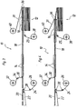
- the figures show a device according to the invention for the stepwise lamination of multilayers in a schematized and simplified side view, wherein the figures show successive process steps.
- the device 10 according to the invention shown in the drawing is used for stepwise lamination of the multilayer 12.
- the device 10 has four pressing devices 14, 16, which are arranged successively in a conveying direction. In each case two of the pressing devices 14, 16 operate in parallel, a Laminiergut 18 is further promoted in each step by the length of two pressing devices 14, 16.
- the two first pressing devices 14 in the conveying direction have heating devices, the two last pressing devices 16 have cooling devices.
- the last two pressing devices 16 are jointly movable by the length of two pressing devices 14, 16, ie a method step in and counter to the conveying direction (see. Figures 1 and 2 ).
- the provision of two parallel operating press devices 14, 16 increases a throughput of the device 10. In principle, each individual Be provided pressing devices and it can be heated in successive presses the lamination in stages to rising temperatures and cooled again (not shown).
- the device 10 with the successive press devices 14, 16 may also be referred to as a step press.
- the conveying direction is from left to right.
- Laminiergut 18 plate-shaped inner layers 20 are the pressing means 14, 16 supplied.
- the inner layers 20 are usually made of an adhesive dielectric, for example of a resin-impregnated glass fiber fabric, the resin melts under temperature and / or pressure and then cured.
- the inner layers 20 are electrically insulating.
- As a means for supplying the inner layers 20 is for example a belt conveyor 22.
- the inner layers 20 reach before the first pressing device 14 on a lower outer layer belt 24, which is unwound from a supply roll 26 and pulleys 28 to the pressing devices 14, 16 is supplied.
- the outer roll 24 is made of a metal / plastic composite film, it has a metal foil, for example made of copper, which adheres to a plastic film 25, for example, polyester.
- the plastic film 25 of the outer layer belt 24 has a higher melting point than the inner layers 20.
- the backsheet 24 is fed so that the metal foil is at the top, i. the inner layers 20 rest on the metal foil of the outer layer band 24.
- An upper outer layer tape 30 is unwound from a supply roll 32 and fed via deflection rollers 34 on an upper side of the inner layers 20, the pressing devices 14, 16.
- the supply roll 32 and the deflection rollers 34 form a device for feeding the upper outer layer belt 30.
- the upper outer layer tape 30 is like the lower outer layer tape 24 a composite film and has a metal foil, for example, of copper, the a plastic film 31, for example of polyester adheres.
- the upper outer layer tape 30 is fed so that the metal foil is down and comes to rest on the inner layers 20.
- the two first pressing devices 14 are opened and the two movable pressing devices 16 are moved by the length of two pressing devices 14, 16, ie one step in the conveying direction.
- the lamination material 18 is conveyed through the device 10 by the length of two pressing devices 14, 16.
- FIG. 3 The two first pressing devices 14 are closed again and heat the laminating product 18.
- the last two pressing devices 16 are opened (FIG. FIG. 3 ) and in two steps by the length of a pressing device 14, 16 against the conveying direction moves back to the two first pressing devices 14.
- the closed pressing devices 14 hold the laminating material 18 so that it is not pushed back by the last pressing devices 16, which are moved back counter to the conveying direction.
- a separator 36 is mounted with two knives, which moves with the movable pressing devices 16.
- the separator 36 separates the laminate 18 after each remindiolos administrat in a space between the inner layers 20 in plates containing the multilayer 12 and the two stacks am Form end device 10.
- Each plate may have one or more multilayers 12 to be separated later. The cutting into the two multilayer 12 having plates takes place in each case FIG. 4 and in FIG. 5 ,
- the plastic films 15, 31 of the outer layer belts 24, 30 are separated from the lamination. This is done by winding on take-up rollers 38, 40, not shown rotary actuators.
- the take-up rollers 38, 40 are arranged at the end of the device 10 above and below the Laminierguts 18.
- the removal of the plastic films 25, 31 from the Laminiergut 18 is possible because the plastic films 25, 31 of the outer layer belts 24, 30 have a higher melting point than the resin of the inner layers 20 and the Laminiergut 18 in the pressing devices 14, 16 not to a melting temperature of Plastic films 25, 31 of the outer layer belts 24, 30 are heated. Because of this, the plastic films 25, 31 of the outer layer belts 24, 30 merely adhere to the lamination material 18 after lamination and do not bond with the lamination material. The plastic films 25, 31 can therefore be removed by lamination from the lamination material 18 after lamination.
- the plastic films 25, 31 of the outer layer belts 24, 30 are folded around the rear edges of the last pressing device 16 and unwound by the movement of the pressing means 16 of the winding rollers 38, 40, as in FIG. 2 you can see.
- the take-up rollers 38, 40 are free or braked rotatable.
- the take-up rollers 38, 40 are driven in rotation and wind the plastic films 25, 31 on.
- the plastic films 25, 31 are handled between the last pressing device 16 and the separating device 36, so that they are not severed when separating the Laminierguts 18 in the multilayer 12.
- the plastic films 25, 31 of the outer layer belts 24, 30 are thus unwound from the supply rollers 26, 32 and wound after lamination on the take-up rollers 38, 40.
- the take-up rollers 38, 40 Form with their rotary drives not shown winding means of a discharge device for the plastic films 25, 31 of the outer layer belts 24, 30.
- the plastic films 25, 31 serve to protect the Laminierguts 18 from contamination. They are brand new and thus free of dirt from the supply rolls 26, 32 unwound.
- the plastic films 25, 31 of the outer layers 24, 30 forming composite films form outermost layers 25, 31 of the outer layer belts 24, 30.
- the metal foils and the plastic films also unwound from each separate supply rolls and the pressing devices 14, 16 are supplied (not shown).
- the removal of the plastic films from the laminating 18 after lamination by winding on the take-up rollers 38, 40 remains unchanged.
- the plastic films can be considered as one of several outer layers of the outer layer tapes.
Landscapes
- Physics & Mathematics (AREA)
- Thermal Sciences (AREA)
- Engineering & Computer Science (AREA)
- Fluid Mechanics (AREA)
- Manufacturing & Machinery (AREA)
- Microelectronics & Electronic Packaging (AREA)
- Lining Or Joining Of Plastics Or The Like (AREA)
- Casting Or Compression Moulding Of Plastics Or The Like (AREA)
- Laminated Bodies (AREA)
- Manufacturing Cores, Coils, And Magnets (AREA)
- Press Drives And Press Lines (AREA)
Description
- Die Erfindung betrifft eine Vorrichtung zum schrittweisen Laminieren von Multilayern mit den Merkmalen des Oberbegriffs des Anspruchs 1, wie sie beispielsweise aus
DE-A1-34 13 053 bekannt ist. - Derartige Vorrichtungen werden auch als Stufenpressen bezeichnet, weil ein Laminiergut schrittweise durch aufeinanderfolgend angeordnete Presseinrichtungen (Pressenstufen) gefördert wird, die jeweils eine ganzzahlige Anzahl der späteren Multilayer aufnehmen und pressen. Die Presseinrichtungen weisen Heiz- und/oder Kühleinrichtungen auf und sind einzeln oder in Gruppen temperierbar. In jeder Presseinrichtung wird das die Multilayer bildende Laminiergut gepresst und auf eine vorgegebene Temperatur erwärmt oder gekühlt und ggf. eine vorgegebene Zeitspanne auf der Temperatur gehalten, bevor alle Presseinrichtungen gemeinsam geöffnet und das Laminiergut einen Schritt, d.h. um eine Presseinrichtung, weiter gefördert wird. Zum Fördern sind zwei Förderbänder auf einer Unter- und einer Oberseite des Laminierguts vorgesehen, deren fördernde Trume alle Presseinrichtungen durchlaufen und die an beiden Enden der Presseinrichtungen um Umlenkrollen umlaufen.
- Multilayer weisen üblicherweise eine Innenlage auf, auf die vorzugsweise beidseitig eine Außenlage laminiert wird. Die Innenlage lässt sich allgemein auch als Träger bezeichnen. Die Außenlage weist bei Multilayern eine Metallfolie, üblicherweise aus Kupfer oder Aluminium auf, aus der nach dem Laminieren durch Ätzen Leiterbahnen hergestellt werden. Zum Laminieren (Verkleben von Außen- und Innenlage) kommmt zwischen die Außenlage und die Innenlage eine oder mehrere Zwischenlagen aus einem elektrisch isolierenden, durch Wärme und Druck schmelzbaren Kunststoff aufweisen. Bei Multilayern werden die Zwischenlagen üblicherweise als Prepreg bezeichnet. Sie können als einzelne Bögen, als separates Band oder im Verbund als an der Metallfolie haftendes Band zugeführt werden. In letzterem Fall wird auch von einer Verbundfolie gesprochen. Um auf beide Seiten der Innenlage mehrere Metallschichten laminieren zu können, kann der Laminiervorgang wiederholt werden, wobei die außenliegenden Metallschichten nach jedem Laminieren zu Leiterbahnen geätzt werden müssen bevor eine weitere Zwischen- und Außenlage laminiert wird. Nach dem Laminieren wird das Laminiergut in Platten getrennt, die eine ganzzahlige Anzahl der späteren Multilayer umfassen. Diese Laminatplatten können bei weiteren Laminierdurchläufen als Innenlagen aufgefasst werden.
- Die Innenlagen werden einzeln in Plattenform oder beim ersten Laminierdurchgang auch als Bänder zugeführt. Die Außenlagen und Zwischenlagen werden üblicherweise als Bänder zugeführt, grundsätzlich ist auch ein Auflegen einzelner Bögen denkbar.
- Außer Multilayern lassen sich mit der erfindungsgemäßen Vorrichtung auch andere Laminate, d.h. Schichtverbundplatten beispielsweise für Kredit- oder Scheckkarten herstellen. Das Laminieren erfolgt üblicherweise in einem evakuierten Raum, in dem die Presseinrichtungen angeordnet sind. Durch Druck- und Temperatureinwirkung in den Presseinrichtungen schmelzen die Innenlage und, sofern vorhanden, die Zwischenlagen auf und verbinden die Lagen des Laminierguts nach dem Abkühlen in der oder den letzten Presseinrichtungen stoffschlüssig miteinander.
- Der Erfindung liegt die Aufgabe zugrunde, eine Vorrichtung zum schrittweisen Laminieren von Multilayern oder allgemein Schichtverbundwerkstoffen vorzuschlagen, die keine umlaufenden Förderbänder zum Fördern des Laminierguts durch die Presseinrichtungen benötigt.
- Diese Aufgabe wird erfindungsgemäß durch die Merkmale des Anspruchs 1 gelöst. Die erfindungsgemäße Vorrichtung weist mindestens eine in Förderrichtung letzte Presseinrichtung auf, die in und entgegen einer Förderrichtung bewegbar ist. Es können mehrere letzte Presseinrichtungen gemeinsam bewegbar sein. Zum Fördern des Laminierguts durch die Presseinrichtungen werden mit Ausnahme der beweglichen letzten Presseinrichtungen alle Presseinrichtungen geöffnet und die geschlossenen, beweglichen Presseinrichtungen werden um die Länge einer Presseinrichtung oder mehrerer Presseinrichtungen, also um einen Schritt, in Förderrichtung bewegt. Dadurch wird das bandförmige Laminiergut um einen Schritt durch die Vorrichtung gefördert. Die geöffneten, nicht bewegten Presseinrichtungen werden anschließend geschlossen und die bewegbaren Presseinrichtungen geöffnet und zurück in ihre Ausgangsposition bewegt, bevor sie wieder geschlossen werden. Das schrittweise Fördern des Laminierguts durch die Presseinrichtungen erfolgt erfindungsgemäß also durch Bewegen der letzten Presseinrichtungen in Förderrichtung. Erforderlich dafür ist, dass mindestens die unterste Lage des Multilayers bzw. Laminierguts ein durchgehendes Band ist, das alle Presseinrichtungen durchsetzt. Vorzugsweise ist auch die oberste Lage des Laminierguts ein durchgehendes Band, um ein Haften an oberen Stempeln der Presseinrichtungen beim Öffnen der Presseinrichtungen zu vermeiden. Alle anderen Lagen des Laminierguts können durchgehende Bänder und/oder Platten oder Bögen sein, die auf dem untersten Band liegen und mit diesem schrittweise durch die Presseinrichtungen gefördert werden.
- Die Erfindung hat zunächst den Vorteil, dass sie ohne separate Förderbänder auskommt, die zusätzlich noch jeweils zwei Umlenkrollen und üblicherweise Spanneinrichtungen benötigen. Weiterer Vorteil ist, dass die Presseinrichtungen das Laminiergut unmittelbar, d.h. ohne zwischenliegendes Förderband, heizen oder kühlen, die Wärmeübertragung ist dadurch verbessert.
- Eine bevorzugte Ausgestaltung der Erfindung weist eine Abführeinrichtung auf, die in Förderrichtung nach der letzten Presseinrichtung angeordnet ist und die mindestens eine äußerste Lage nach dem Laminieren vom Laminiergut entfernt. Die äußerste Lage kann eine Lage einer mehrere Lagen (Schichten) aufweisenden Außenlage sein. Als Außenlage wird in diesem Fall also eine Verbundfolie mit beispielsweise einer Metallfolie und einer oder mehreren Kunststofffolien zugeführt, von denen nach dem Laminieren die äußerste (Kunststoff-) Lage wieder entfernt wird. Es können auch mehrere Außenlagen bzw. Außen- und Zwischenlagen zugeführt werden, von denen die äußerste Lage nach dem Laminieren wieder entfernt wird. Die zu entfernende Lage weist vorzugsweise einen höheren Schmelzpunkt auf, d.h. sie wird beim Heizen und Pressen nicht angeschmolzen sondern haftet auch nach dem Laminieren nur ohne Stoffschluss am Laminiergut. Die äußerste Lage kann deswegen auch aus Metall bestehen (Aluminiumfolie). Vorzugsweise werden äußerste Lagen auf der Ober- und der Unterseite des Laminierguts vom Laminiergut entfernt.
- Die Zu- und Abführeinrichtungen weisen beispielsweise Wickeleinrichtungen auf, von der die Außenlagen ab- und aufgewickelt werden. Die Abführeinrichtung weist zusätzlich einen Drehantrieb zum Aufwickeln der äußersten Lage auf. Die äußerste Lage, die erfindungsgemäß nach dem Laminieren vom Laminiergut entfernt wird, hat den Vorteil, dass eine Verschmutzung des Laminierguts vermieden wird. Die äußerste Lage wird neu und damit unverschmutzt den Presseinrichtungen zugeführt und nach dem Laminieren entfernt. Eine Reinigung, wie sie bei umlaufenden Förderbändern unbedingt erforderlich ist, entfällt. Es wird vermieden, dass Schmutzpartikel in die Presseinrichtungen eingetragen werden, was bei umlaufenden Förderbändern passieren kann. Dies ist deshalb ein großer Vorteil, weil bereits kleinste Schmutzpartikel Multilayer oder auch sonstige Laminate wie Kredit- und Scheckkarten unbrauchbar machen. Durch Entfall einer ansonsten erforderlichen Reinigungseinrichtung für umlaufende Förderbänder ermöglicht das erfindungsgemäße Entfernen der äußersten Lage vom Laminiergut nach dem Laminieren eine preisgünstigere Laminiervorrichtung. Zudem ist die Gefahr von Ausschuss durch Schmutzeintrag verringert. Weiterer Vorteil ist, dass ein rücklaufendes Trum eines umlaufenden Förderbandes entfällt, so dass die Presseinrichtungen besser zugänglich und einfacher aufstellbar und ihrer Konstruktion einfacher zu gestalten sind.
- Eine Ausgestaltung der Erfindung sieht eine Trenneinrichtung vor, die das Laminiergut nach dem Laminieren und nach Entfernen der äußersten Lagen in Platten oder Bögen trennt, die eine ganze Anzahl von Multilayern umfassen.
- Die Erfindung wird nachfolgend anhand eines in der Zeichnung dargestellten Ausführungsbeispiels näher erläutert. Die Figuren zeigen eine erfindungsgemäße Vorrichtung zum schrittweisen Laminieren von Multilayern in einer schematisierten und vereinfachten Seitenansicht, wobei die Figuren aufeinanderfolgende Verfahrensschritte zeigen.
- Die in der Zeichnung dargestellte, erfindungsgemäße Vorrichtung 10 dient zum schrittweisen Laminieren vom Multilayern 12. Die Vorrichtung 10 weist vier Presseinrichtungen 14, 16 auf, die in einer Förderrichtung aufeinanderfolgend angeordnet sind. Jeweils zwei der Presseinrichtungen 14, 16 arbeiten parallel, ein Laminiergut 18 wird in jedem Verfahrensschritt um die Länge zweier Presseinrichtungen 14, 16 weitergefördert.
- Die beiden in Förderrichtung ersten Presseinrichtungen 14 weisen Heizeinrichtungen auf, die beiden letzten Presseinrichtungen 16 weisen Kühleinrichtungen auf. Die beiden letzten Presseinrichtungen 16 sind gemeinsam um die Länge zweier Presseinrichtungen 14, 16, d.h. einen Verfahrensschritt in und entgegen der Förderrichtung bewegbar (vgl.
Figuren 1 und 2 ). Das Vorsehen jeweils zweier parallel arbeitender Presseinrichtungen 14, 16 erhöht einen Durchsatz der Vorrichtung 10. Grundsätzlich können auch jeweils einzelne Presseinrichtungen vorgesehen sein und es kann das Laminiergut in aufeinanderfolgenden Presseinrichtungen stufenweise auf steigende Temperaturen erwärmt und wieder abgekühlt werden (nicht dargestellt). - Die Vorrichtung 10 mit den aufeinanderfolgenden Presseinrichtungen 14, 16 kann auch als Stufenpresse bezeichnet werden. In der Zeichnung ist die Förderrichtung von links nach rechts.
- Als Laminiergut 18 werden plattenförmige Innenlagen 20 den Presseinrichtungen 14, 16 zugeführt. Die Innenlagen 20 bestehen üblicherweise aus einem klebfähigen Dielektrikum, beispielsweise aus einem harzimprägnierten Glasfasergewebe, dessen Harz unter Temperatur- und/oder Druckeinwirkung schmilzt und anschließend aushärtet. Die Innenlagen 20 sind elektrisch isolierend. Als Einrichtung zum Zuführen der Innenlagen 20 dient beispielsweise ein Bandförderer 22. Die Innenlagen 20 gelangen vor der ersten Presseinrichtung 14 auf ein unteres Außenlageband 24, welches von einer Vorratsrolle 26 abgewickelt und über Umlenkrollen 28 den Presseinrichtungen 14, 16 zugeführt wird. Die Vorratsrolle 26 und die Umlenkrollen 28 bilden eine Einrichtung zum Zuführen des unteren Außenlagebandes 24. Das Außenlageband 24 besteht aus einer Metall-/Kunststoff-Verbundfolie, sie weist eine Metallfolie beispielsweise aus Kupfer auf, die an einer Kunststofffolie 25 aus beispielsweise Polyester haftet. Die Kunststofffolie 25 des Außenlagebandes 24 weist einen höheren Schmelzpunkt als die Innenlagen 20 auf. Das Außenlageband 24 wird so zugeführt, dass die Metallfolie sich oben befindet, d.h. die Innenlagen 20 liegen auf der Metallfolie des Außenlagebandes 24 auf.
- Ein oberes Außenlageband 30 wird von einer Vorratsrolle 32 abgewickelt und über Umlenkrollen 34 auf eine Oberseite der Innenlagen 20 aufliegend den Presseinrichtungen 14, 16 zugeführt. Die Vorratsrolle 32 und die Umlenkrollen 34 bilden eine Einrichtung zum Zuführen des oberen Außenlagebandes 30. Das obere Außenlageband 30 ist ebenso wie das untere Außenlageband 24 eine Verbundfolie und weist eine Metallfolie beispielsweise aus Kupfer auf, die an einer Kunststofffolie 31, beispielsweise aus Polyester haftet. Das obere Außenlageband 30 wird so zugeführt, dass die Metallfolie sich unten befindet und auf den Innenlagen 20 zu liegen kommt.
- In einem ersten, in
Figur 1 dargestellten Verfahrensschritt sind alle vier Presseinrichtungen 14, 16 geschlossen, in den ersten beiden Presseinrichtungen 14 wird das Laminiergut 18 unter Druck bis zum Schmelzen der Innenlagen 20 erwärmt. In den beiden letzten Presseinrichtungen 16 wird das Laminiergut 18 gekühlt, so dass das Harz der Innenlagen 10 aushärtet und sich stoffschlüssig mit den Metallfolien der Außenlagebänder 24, 30 verbindet. Die Kunststofffolien 25, 31 der Außenlagebänder 24, 30, die einen höheren Schmelzpunkt als die Innenlagen 20 aufweisen, werden nicht angeschmolzen. - In einem zweiten, in
Figur 2 dargestellten Verfahrensschritt werden die beiden ersten Presseinrichtungen 14 geöffnet und die bewegbaren beiden letzten Presseinrichtungen 16 werden um die Länge zweier Presseinrichtungen 14, 16, d.h. einen Schritt in Förderrichtung bewegt. Dadurch wird das Laminiergut 18 um die Länge zweier Presseinrichtungen 14, 16 durch die Vorrichtung 10 gefördert. In einem dritten, inFigur 3 dargestellten Verfahrensschritt werden die beiden ersten Presseinrichtungen 14 wieder geschlossen und erwärmen das Laminiergut 18. Die beiden letzten Presseinrichtungen 16 werden geöffnet (Figur 3 ) und in zwei Schritten um jeweils die Länge einer Presseinrichtung 14, 16 entgegen der Förderrichtung zurück zu den beiden ersten Presseinrichtungen 14 bewegt. Die geschlossenen Presseinrichtungen 14 halten das Laminiergut 18, so dass es nicht von den entgegen der Förderrichtung zurückbewegten letzten Presseinrichtungen 16 zurückgeschoben wird. - An einem in Förderrichtung hinteren Ende der letzten Presseinrichtung 16 ist eine Trenneinrichtung 36 mit zwei Messern angebracht, die sich mit den bewegbaren Presseinrichtungen 16 mitbewegt. Die Trenneinrichtung 36 trennt das Laminiergut 18 nach jedem Rückbewegungsschritt in einem Zwischenraum zwischen den Innenlagen 20 in Platten, die die Multilayer 12 enthalten und die zwei Stapel am Ende Vorrichtung 10 bilden. Jede Platte kann einen oder mehrere, später voneinander zu trennende Multilayer 12 aufweisen. Das Schneiden in die beiden die Multilayer 12 aufweisenden Platten erfolgt jeweils in
Figur 4 und inFigur 5 . - Nach dem, Laminieren werden die Kunststofffolien 15, 31 der Außenlagebänder 24, 30 vom Laminiergut getrennt. Dies erfolgt durch Aufwickeln auf Aufwickelrollen 38, 40, die nicht dargestellte Drehantriebe aufweisen. Die Aufwickelrollen 38, 40 sind am Ende der Vorrichtung 10 ober- und unterhalb des Laminierguts 18 angeordnet. Das Abziehen der Kunststofffolien 25, 31 vom Laminiergut 18 ist möglich, weil die Kunststofffolien 25, 31 der Außenlagebänder 24, 30 einen höheren Schmelzpunkt als das Harz der Innenlagen 20 aufweisen und das Laminiergut 18 in den Presseinrichtungen 14, 16 nicht bis auf eine Schmelztemperatur der Kunststofffolien 25, 31 der Außenlagebänder 24, 30 erwärmt werden. Deswegen haften die Kunststofffolien 25, 31 der Außenlagebänder 24, 30 nach dem Laminieren lediglich am Laminiergut 18 und verbinden sich nicht stoffschlüssig mit dem Laminiergut 18. Die Kunststofffolien 25, 31 lassen sich daher nach dem Laminieren durch Abziehen vom Laminiergut 18 entfernen.
- Beim Bewegen der beiden letzten Presseinrichtungen 16 in Förderrichtung werden die Kunststofffolien 25, 31 der Außenlagebänder 24, 30 um hintere Ränder der letzten Presseinrichtung 16 umgeschlagen und durch die Bewegung der Presseinrichtungen 16 von den Aufwickelrollen 38, 40 abgewickelt, wie in
Figur 2 zu sehen ist. Die Aufwickelrollen 38, 40 sind dabei frei oder gebremst drehbar. Beim Zurückbewegen der beiden letzten Presseinrichtungen 16 entgegen der Förderrichtung werden die Aufwickelrollen 38, 40 drehend angetrieben und wickeln die Kunststofffolien 25, 31 auf. Die Kunststofffolien 25, 31 werden zwischen der letzten Presseinrichtung 16 und der Trenneinrichtung 36 umgeschlagen, so dass sie beim Trennen des Laminierguts 18 in die Multilayer 12 nicht durchtrennt werden. Die Kunststofffolien 25, 31 der Außenlagebänder 24, 30 werden also von den Vorratsrollen 26, 32 abgewickelt und nach dem Laminieren auf die Aufwickelrollen 38, 40 aufgewickelt. Die Aufwickelrollen 38, 40 bilden mit ihren nicht dargestellten Drehantrieben Wickeleinrichtungen einer Abführeinrichtung für die Kunststofffolien 25, 31 der Außenlagebänder 24, 30. Die Kunststofffolien 25, 31 dienen einem Schutz des Laminierguts 18 vor Verschmutzung. Sie werden fabrikneu und damit schmutzfrei von den Vorratsrollen 26, 32 abgewickelt. - Die Kunststofffolien 25, 31 der die Außenlagen 24, 30 bildenden Verbundfolien bilden äußerste Lagen 25, 31 der Außenlagebänder 24, 30. Anstelle der Verwendung von Verbundfolien als Außenlagebänder 24, 30 können die Metallfolien und die Kunststofffolien auch von jeweils getrennten Vorratsrollen abgewickelt und den Presseinrichtungen 14, 16 zugeführt werden (nicht dargestellt). Das Entfernen der Kunststofffolien vom Laminiergut 18 nach dem Laminieren durch Aufwickeln auf die Aufwickelrollen 38, 40 bleibt unverändert. In diesem Fall können die Kunststofffolien als eine von mehreren Außenlagen der Außenlagebänder aufgefasst werden.
Claims (4)
- Vorrichtung (10) zum schrittweisen Laminieren von Multilayern (12),- mit einer Anzahl Presseinrichtungen (14, 16), die aufeinanderfolgend entlang einer Förderstrecke angeordnet sind, die Heiz- und/oder Kühleinrichtungen aufweisen und die einzeln oder in Gruppen temperierbar sind,- mit einer Einrichtung (22) zum Zuführen einer Innenlage (20) des Multilayers (12, 18) in eine in einer Förderrichtung erste Presseinrichtung (14) und mit mindestens einer Einrichtung zum Zuführen mindestens eines Außenlagebandes (24,30) des Multilayers (12, 18) auf eine Außenseite der Innenlage und in die in Förderrichtung erste Presseinrichtung (14)dadurch gekennzeichnet, dass mindestens eine in Förderrichtung letzte Presseinrichtung (16) in und entgegen der Förderrichtung bewegbar ist.
- Vorrichtung nach Anspruch 1, dadurch gekennzeichnet, dass die Vorrichtung (10) eine Abführeinrichtung (38, 40) aufweist, die in Förderrichtung nach der letzten Presseinrichtung (16) angeordnet ist und die mindestens eine äußerste Lage (25, 31) der Außenlage (24, 30) von dem Multilayer (12, 18) entfernt.
- Vorrichtung nach Anspruch 2, dadurch gekennzeichnet, dass die Abführeinrichtung (38, 40) eine Wickeleinrichtung (38, 40) mit einem Drehantrieb aufweist, die die mindestens eine Lage (25, 31) der Außenlage (24, 30) oder die mindestens eine von mehreren Außenlagen nach der letzten Presseinrichtung (16) aufwickelt.
- Vorrichtung nach einem der Ansprüche 1 bis 3, dadurch gekennzeichnet, dass die Vorrichtung eine Trenneinrichtung (36) aufweist, die in Förderrichtung nach der letzten Presseinrichtung (16) und nach der Abführeinrichtung (38, 40) angeordnet ist und die die Multilayer (12) voneinander trennt.
Applications Claiming Priority (2)
| Application Number | Priority Date | Filing Date | Title |
|---|---|---|---|
| DE10335693A DE10335693B3 (de) | 2003-08-05 | 2003-08-05 | Vorrichtung zum schrittweisen Laminieren von Multilayern |
| PCT/DE2004/001335 WO2005014284A1 (de) | 2003-08-05 | 2004-06-25 | Vorrichtung zum schrittweisen laminieren von multilayern |
Publications (2)
| Publication Number | Publication Date |
|---|---|
| EP1651439A1 EP1651439A1 (de) | 2006-05-03 |
| EP1651439B1 true EP1651439B1 (de) | 2008-04-09 |
Family
ID=34129483
Family Applications (1)
| Application Number | Title | Priority Date | Filing Date |
|---|---|---|---|
| EP04738784A Expired - Lifetime EP1651439B1 (de) | 2003-08-05 | 2004-06-25 | Vorrichtung zum schrittweisen laminieren von multilayern |
Country Status (7)
| Country | Link |
|---|---|
| EP (1) | EP1651439B1 (de) |
| KR (1) | KR101100525B1 (de) |
| CN (1) | CN100522608C (de) |
| AT (1) | ATE391600T1 (de) |
| DE (3) | DE10335693B3 (de) |
| TW (1) | TWI265867B (de) |
| WO (1) | WO2005014284A1 (de) |
Families Citing this family (8)
| Publication number | Priority date | Publication date | Assignee | Title |
|---|---|---|---|---|
| DE102007010483B4 (de) * | 2007-03-03 | 2010-09-30 | Laminatepark Gmbh & Co. Kg | Verfahren zur Herstellung eines Paneels mit Kern und Dekorpapier |
| DE102008031573B4 (de) * | 2008-07-07 | 2012-06-28 | Carl Freudenberg Kg | Dehnbares Vlies mit Leiterstrukturen |
| CN103496608B (zh) * | 2013-09-29 | 2016-01-13 | 大连橡胶塑料机械股份有限公司 | 胶片连续层合装置 |
| DE102015012242B4 (de) * | 2015-09-18 | 2019-06-19 | Leonhard Kurz Stiftung & Co. Kg | Verfahren und Vorrichtung zur Herstellung eines mit einem Schichtstoff kaschierten 3D-Substrates |
| DE102018205803A1 (de) * | 2018-04-17 | 2019-10-17 | Homag Gmbh | Beschichtungsvorrichtung |
| DE102018205802A1 (de) * | 2018-04-17 | 2019-10-17 | Homag Gmbh | Vorrichtung zum Auftragen eines Haftmittels sowie Verfahren |
| CN112644827B (zh) * | 2020-12-21 | 2023-06-30 | 海峡(晋江)伞业科技创新中心有限公司 | 一种自动化贴标流水线 |
| CN114158206B (zh) * | 2021-11-02 | 2022-06-21 | 深圳市方泰设备技术有限公司 | 一种叠合机 |
Family Cites Families (8)
| Publication number | Priority date | Publication date | Assignee | Title |
|---|---|---|---|---|
| DE3413053A1 (de) * | 1983-04-29 | 1985-01-24 | Harro 7500 Karlsruhe Manias | Vorrichtung zum einschweissen von flaechigen gegenstaenden zwischen kunststoffolien |
| DE3413434A1 (de) * | 1984-04-10 | 1985-10-17 | Dielektra GmbH, 5000 Köln | Verfahren zum kontinuierlichen herstellen von kupferkaschiertem basismaterial fuer leiterplatten |
| DD300969C4 (de) * | 1989-09-13 | 2002-01-24 | Erfurt Umformtechnik Gmbh | Entstapel- und Transportvorrichtung fuer Platienen |
| US5470428A (en) * | 1993-06-24 | 1995-11-28 | Alfred D. Lobo Co., L.P.A. | Flow-through linear transfer system for making credit cards and the like, from synthetic resinous sheets |
| JP3084352B2 (ja) * | 1995-08-28 | 2000-09-04 | 太陽インキ製造株式会社 | 銅箔ラミネート方式ビルドアップ用絶縁樹脂組成物とこれを用いた多層プリント配線板の製造方法 |
| US6000327A (en) * | 1995-11-02 | 1999-12-14 | Komatsu Ltd. | Work conveyor of transfer press |
| DE19962081A1 (de) * | 1999-12-21 | 2001-06-28 | Buerkle Gmbh Robert | Verfahren und Vorrichtung zur Herstellung laminierter Plastikkarten |
| DE20017405U1 (de) * | 2000-10-11 | 2002-02-21 | AUTEFA Automation GmbH, 86316 Friedberg | Ballenpressanlage |
-
2003
- 2003-08-05 DE DE10335693A patent/DE10335693B3/de not_active Expired - Fee Related
-
2004
- 2004-06-25 CN CNB2004800224257A patent/CN100522608C/zh not_active Expired - Fee Related
- 2004-06-25 WO PCT/DE2004/001335 patent/WO2005014284A1/de not_active Ceased
- 2004-06-25 DE DE502004006783T patent/DE502004006783D1/de not_active Expired - Lifetime
- 2004-06-25 AT AT04738784T patent/ATE391600T1/de active
- 2004-06-25 EP EP04738784A patent/EP1651439B1/de not_active Expired - Lifetime
- 2004-06-25 DE DE112004001935T patent/DE112004001935D2/de not_active Expired - Fee Related
- 2004-06-25 KR KR1020067002337A patent/KR101100525B1/ko not_active Expired - Fee Related
- 2004-06-29 TW TW093119001A patent/TWI265867B/zh active
Also Published As
| Publication number | Publication date |
|---|---|
| WO2005014284A1 (de) | 2005-02-17 |
| TWI265867B (en) | 2006-11-11 |
| DE10335693B3 (de) | 2005-04-28 |
| TW200518930A (en) | 2005-06-16 |
| KR20060052966A (ko) | 2006-05-19 |
| ATE391600T1 (de) | 2008-04-15 |
| EP1651439A1 (de) | 2006-05-03 |
| DE112004001935D2 (de) | 2006-10-26 |
| KR101100525B1 (ko) | 2011-12-29 |
| DE502004006783D1 (de) | 2008-05-21 |
| CN100522608C (zh) | 2009-08-05 |
| CN1832855A (zh) | 2006-09-13 |
Similar Documents
| Publication | Publication Date | Title |
|---|---|---|
| EP0134820B1 (de) | Verfahren zum Herstellen von Kunststoffkarten | |
| EP2408620B1 (de) | Vorrichtung und verfahren zum laminieren einer mehrschichtigen thermoplastischen folienanordnung | |
| EP0344765B1 (de) | Verfahren und Anordnung zum Verkleben flächiger Werkstücke | |
| DE69033572T2 (de) | Verfahren zum Herstellen einer magnetischen Karte | |
| EP0531251B1 (de) | Verfahren zum Herstellen eines Wabenkerns aus einer bandförmigen Folie, Vorrichtung zur Durchführung des Verfahrens und Verwendung des Wabenkerns als Wabenkern von kontinuierlich hergestellten Verbundplatten | |
| EP0485895B1 (de) | Vorrichtung und Verfahren zum Herstellen eines mehrschichtigen Folienverbundes | |
| EP1609597A2 (de) | Laminator zum Herstellen von Schichtkörpern | |
| EP0120192A2 (de) | Verfahren zur kontinuierlichen Herstellung kupferkaschierter Elektrolaminate und Vorrichtung zur DurchfÜhrung des Verfahrens | |
| EP0116659B1 (de) | Einrichtung zum beiderseitigen Aufbringen von Folien oder dergl. auf plattenförmige Werkstücke und Verfahren zum Betrieb derselben | |
| DE3420409A1 (de) | Laminierstation | |
| DE19861187B4 (de) | Vorrichtung zum kontinuierlichen Laminieren | |
| EP0347729B1 (de) | Verfahren und Vorrichtung zur Herstellung eines endlosen Wabenbandes | |
| DE69507674T2 (de) | Verfahren zum Herstellen eines flachen Kabelbaumes | |
| EP0996087B1 (de) | Vorrichtung und Verfahren zur Bearbeitung einer Bahn, insbesondere eines Transponder-Streifens | |
| DE112010001156T5 (de) | Laminiereinrichtung und Laminierverfahren für elne Solarbatterie | |
| WO2005014284A1 (de) | Vorrichtung zum schrittweisen laminieren von multilayern | |
| DE3320078A1 (de) | Anordnung und verfahren zur herstellung von geschichteten einheiten | |
| DE19731538C2 (de) | Anlage zum Herstellen von Laminaten, insbesondere von Industrielaminaten | |
| DE4441552A1 (de) | Verfahren und Vorrichtung zum Herstellen von Kunststoffkarten, z. B. Ausweiskarten, Kreditkarten, Scheckkarten o. dgl. | |
| EP3695967B1 (de) | Verfahren und vorrichtung zur herstellung eines flächigen informationsträgers aus kunststoff | |
| EP0376007A1 (de) | Maschine zum Herstellen von Tragetaschen mit Grifflöchern und diese umgebenden angeschweissten Verstärkungszetteln aus thermoplastischem Kunststoff | |
| DE19859613C2 (de) | Presspaketaufbau und Verfahren zu dessen Herstellung | |
| DE10140450B4 (de) | Verfahren und Vorrichtung zum Beschichten einer Profilschiene | |
| DE3413053A1 (de) | Vorrichtung zum einschweissen von flaechigen gegenstaenden zwischen kunststoffolien | |
| DE4103867A1 (de) | Laminiermaschine |
Legal Events
| Date | Code | Title | Description |
|---|---|---|---|
| PUAI | Public reference made under article 153(3) epc to a published international application that has entered the european phase |
Free format text: ORIGINAL CODE: 0009012 |
|
| 17P | Request for examination filed |
Effective date: 20060125 |
|
| AK | Designated contracting states |
Kind code of ref document: A1 Designated state(s): AT BE BG CH CY CZ DE DK EE ES FI FR GB GR HU IE IT LI LU MC NL PL PT RO SE SI SK TR |
|
| GRAP | Despatch of communication of intention to grant a patent |
Free format text: ORIGINAL CODE: EPIDOSNIGR1 |
|
| GRAS | Grant fee paid |
Free format text: ORIGINAL CODE: EPIDOSNIGR3 |
|
| DAX | Request for extension of the european patent (deleted) | ||
| GRAA | (expected) grant |
Free format text: ORIGINAL CODE: 0009210 |
|
| AK | Designated contracting states |
Kind code of ref document: B1 Designated state(s): AT BE BG CH CY CZ DE DK EE ES FI FR GB GR HU IE IT LI LU MC NL PL PT RO SE SI SK TR |
|
| REG | Reference to a national code |
Ref country code: GB Ref legal event code: FG4D Free format text: NOT ENGLISH |
|
| REG | Reference to a national code |
Ref country code: CH Ref legal event code: EP |
|
| REG | Reference to a national code |
Ref country code: IE Ref legal event code: FG4D Free format text: LANGUAGE OF EP DOCUMENT: GERMAN |
|
| REF | Corresponds to: |
Ref document number: 502004006783 Country of ref document: DE Date of ref document: 20080521 Kind code of ref document: P |
|
| PG25 | Lapsed in a contracting state [announced via postgrant information from national office to epo] |
Ref country code: SI Free format text: LAPSE BECAUSE OF FAILURE TO SUBMIT A TRANSLATION OF THE DESCRIPTION OR TO PAY THE FEE WITHIN THE PRESCRIBED TIME-LIMIT Effective date: 20080409 |
|
| NLV1 | Nl: lapsed or annulled due to failure to fulfill the requirements of art. 29p and 29m of the patents act | ||
| PG25 | Lapsed in a contracting state [announced via postgrant information from national office to epo] |
Ref country code: FI Free format text: LAPSE BECAUSE OF FAILURE TO SUBMIT A TRANSLATION OF THE DESCRIPTION OR TO PAY THE FEE WITHIN THE PRESCRIBED TIME-LIMIT Effective date: 20080409 Ref country code: ES Free format text: LAPSE BECAUSE OF FAILURE TO SUBMIT A TRANSLATION OF THE DESCRIPTION OR TO PAY THE FEE WITHIN THE PRESCRIBED TIME-LIMIT Effective date: 20080720 Ref country code: BG Free format text: LAPSE BECAUSE OF FAILURE TO SUBMIT A TRANSLATION OF THE DESCRIPTION OR TO PAY THE FEE WITHIN THE PRESCRIBED TIME-LIMIT Effective date: 20080709 Ref country code: NL Free format text: LAPSE BECAUSE OF FAILURE TO SUBMIT A TRANSLATION OF THE DESCRIPTION OR TO PAY THE FEE WITHIN THE PRESCRIBED TIME-LIMIT Effective date: 20080409 Ref country code: PT Free format text: LAPSE BECAUSE OF FAILURE TO SUBMIT A TRANSLATION OF THE DESCRIPTION OR TO PAY THE FEE WITHIN THE PRESCRIBED TIME-LIMIT Effective date: 20080910 |
|
| PG25 | Lapsed in a contracting state [announced via postgrant information from national office to epo] |
Ref country code: PL Free format text: LAPSE BECAUSE OF FAILURE TO SUBMIT A TRANSLATION OF THE DESCRIPTION OR TO PAY THE FEE WITHIN THE PRESCRIBED TIME-LIMIT Effective date: 20080409 |
|
| REG | Reference to a national code |
Ref country code: IE Ref legal event code: FD4D |
|
| BERE | Be: lapsed |
Owner name: MASCHINENFABRIK LAUFFER G.M.B.H. & CO. KG Effective date: 20080630 |
|
| ET | Fr: translation filed | ||
| PG25 | Lapsed in a contracting state [announced via postgrant information from national office to epo] |
Ref country code: IE Free format text: LAPSE BECAUSE OF FAILURE TO SUBMIT A TRANSLATION OF THE DESCRIPTION OR TO PAY THE FEE WITHIN THE PRESCRIBED TIME-LIMIT Effective date: 20080409 Ref country code: CZ Free format text: LAPSE BECAUSE OF FAILURE TO SUBMIT A TRANSLATION OF THE DESCRIPTION OR TO PAY THE FEE WITHIN THE PRESCRIBED TIME-LIMIT Effective date: 20080409 Ref country code: DK Free format text: LAPSE BECAUSE OF FAILURE TO SUBMIT A TRANSLATION OF THE DESCRIPTION OR TO PAY THE FEE WITHIN THE PRESCRIBED TIME-LIMIT Effective date: 20080409 Ref country code: MC Free format text: LAPSE BECAUSE OF NON-PAYMENT OF DUE FEES Effective date: 20080630 Ref country code: SE Free format text: LAPSE BECAUSE OF FAILURE TO SUBMIT A TRANSLATION OF THE DESCRIPTION OR TO PAY THE FEE WITHIN THE PRESCRIBED TIME-LIMIT Effective date: 20080709 |
|
| PLBE | No opposition filed within time limit |
Free format text: ORIGINAL CODE: 0009261 |
|
| STAA | Information on the status of an ep patent application or granted ep patent |
Free format text: STATUS: NO OPPOSITION FILED WITHIN TIME LIMIT |
|
| PG25 | Lapsed in a contracting state [announced via postgrant information from national office to epo] |
Ref country code: RO Free format text: LAPSE BECAUSE OF FAILURE TO SUBMIT A TRANSLATION OF THE DESCRIPTION OR TO PAY THE FEE WITHIN THE PRESCRIBED TIME-LIMIT Effective date: 20080409 Ref country code: SK Free format text: LAPSE BECAUSE OF FAILURE TO SUBMIT A TRANSLATION OF THE DESCRIPTION OR TO PAY THE FEE WITHIN THE PRESCRIBED TIME-LIMIT Effective date: 20080409 |
|
| 26N | No opposition filed |
Effective date: 20090112 |
|
| GBPC | Gb: european patent ceased through non-payment of renewal fee |
Effective date: 20080709 |
|
| PG25 | Lapsed in a contracting state [announced via postgrant information from national office to epo] |
Ref country code: BE Free format text: LAPSE BECAUSE OF NON-PAYMENT OF DUE FEES Effective date: 20080630 |
|
| PG25 | Lapsed in a contracting state [announced via postgrant information from national office to epo] |
Ref country code: EE Free format text: LAPSE BECAUSE OF FAILURE TO SUBMIT A TRANSLATION OF THE DESCRIPTION OR TO PAY THE FEE WITHIN THE PRESCRIBED TIME-LIMIT Effective date: 20080409 |
|
| PG25 | Lapsed in a contracting state [announced via postgrant information from national office to epo] |
Ref country code: GB Free format text: LAPSE BECAUSE OF NON-PAYMENT OF DUE FEES Effective date: 20080709 |
|
| REG | Reference to a national code |
Ref country code: CH Ref legal event code: NV Representative=s name: ABACUS PATENTANWAELTE KLOCKE SPAETH BARTH |
|
| PG25 | Lapsed in a contracting state [announced via postgrant information from national office to epo] |
Ref country code: IT Free format text: LAPSE BECAUSE OF NON-PAYMENT OF DUE FEES Effective date: 20080625 |
|
| PG25 | Lapsed in a contracting state [announced via postgrant information from national office to epo] |
Ref country code: CY Free format text: LAPSE BECAUSE OF FAILURE TO SUBMIT A TRANSLATION OF THE DESCRIPTION OR TO PAY THE FEE WITHIN THE PRESCRIBED TIME-LIMIT Effective date: 20080409 |
|
| PG25 | Lapsed in a contracting state [announced via postgrant information from national office to epo] |
Ref country code: HU Free format text: LAPSE BECAUSE OF FAILURE TO SUBMIT A TRANSLATION OF THE DESCRIPTION OR TO PAY THE FEE WITHIN THE PRESCRIBED TIME-LIMIT Effective date: 20081010 Ref country code: LU Free format text: LAPSE BECAUSE OF NON-PAYMENT OF DUE FEES Effective date: 20080625 |
|
| PG25 | Lapsed in a contracting state [announced via postgrant information from national office to epo] |
Ref country code: TR Free format text: LAPSE BECAUSE OF FAILURE TO SUBMIT A TRANSLATION OF THE DESCRIPTION OR TO PAY THE FEE WITHIN THE PRESCRIBED TIME-LIMIT Effective date: 20080409 |
|
| PG25 | Lapsed in a contracting state [announced via postgrant information from national office to epo] |
Ref country code: GR Free format text: LAPSE BECAUSE OF FAILURE TO SUBMIT A TRANSLATION OF THE DESCRIPTION OR TO PAY THE FEE WITHIN THE PRESCRIBED TIME-LIMIT Effective date: 20080710 |
|
| PGRI | Patent reinstated in contracting state [announced from national office to epo] |
Ref country code: IT Effective date: 20110616 |
|
| PGFP | Annual fee paid to national office [announced via postgrant information from national office to epo] |
Ref country code: AT Payment date: 20120529 Year of fee payment: 9 |
|
| PGFP | Annual fee paid to national office [announced via postgrant information from national office to epo] |
Ref country code: IT Payment date: 20130618 Year of fee payment: 10 Ref country code: FR Payment date: 20130624 Year of fee payment: 10 |
|
| PGFP | Annual fee paid to national office [announced via postgrant information from national office to epo] |
Ref country code: CH Payment date: 20130925 Year of fee payment: 10 |
|
| REG | Reference to a national code |
Ref country code: DE Ref legal event code: R082 Ref document number: 502004006783 Country of ref document: DE Representative=s name: ABACUS PATENTANWAELTE, DE |
|
| PGFP | Annual fee paid to national office [announced via postgrant information from national office to epo] |
Ref country code: DE Payment date: 20140630 Year of fee payment: 11 |
|
| REG | Reference to a national code |
Ref country code: CH Ref legal event code: PL |
|
| REG | Reference to a national code |
Ref country code: AT Ref legal event code: MM01 Ref document number: 391600 Country of ref document: AT Kind code of ref document: T Effective date: 20140625 |
|
| REG | Reference to a national code |
Ref country code: FR Ref legal event code: ST Effective date: 20150227 |
|
| PG25 | Lapsed in a contracting state [announced via postgrant information from national office to epo] |
Ref country code: CH Free format text: LAPSE BECAUSE OF NON-PAYMENT OF DUE FEES Effective date: 20140630 Ref country code: IT Free format text: LAPSE BECAUSE OF NON-PAYMENT OF DUE FEES Effective date: 20140625 Ref country code: LI Free format text: LAPSE BECAUSE OF NON-PAYMENT OF DUE FEES Effective date: 20140630 |
|
| PG25 | Lapsed in a contracting state [announced via postgrant information from national office to epo] |
Ref country code: AT Free format text: LAPSE BECAUSE OF NON-PAYMENT OF DUE FEES Effective date: 20140625 Ref country code: FR Free format text: LAPSE BECAUSE OF NON-PAYMENT OF DUE FEES Effective date: 20140630 |
|
| REG | Reference to a national code |
Ref country code: DE Ref legal event code: R119 Ref document number: 502004006783 Country of ref document: DE |
|
| PG25 | Lapsed in a contracting state [announced via postgrant information from national office to epo] |
Ref country code: DE Free format text: LAPSE BECAUSE OF NON-PAYMENT OF DUE FEES Effective date: 20160101 |