EP1651379B1 - Fügestellenstruktur für ein reibschweissverfahren und verfahren zum fügen - Google Patents
Fügestellenstruktur für ein reibschweissverfahren und verfahren zum fügen Download PDFInfo
- Publication number
- EP1651379B1 EP1651379B1 EP04763595A EP04763595A EP1651379B1 EP 1651379 B1 EP1651379 B1 EP 1651379B1 EP 04763595 A EP04763595 A EP 04763595A EP 04763595 A EP04763595 A EP 04763595A EP 1651379 B1 EP1651379 B1 EP 1651379B1
- Authority
- EP
- European Patent Office
- Prior art keywords
- shaft
- hub part
- joint
- connecting flange
- friction welding
- Prior art date
- Legal status (The legal status is an assumption and is not a legal conclusion. Google has not performed a legal analysis and makes no representation as to the accuracy of the status listed.)
- Expired - Lifetime
Links
Images

Classifications
-
- F—MECHANICAL ENGINEERING; LIGHTING; HEATING; WEAPONS; BLASTING
- F16—ENGINEERING ELEMENTS AND UNITS; GENERAL MEASURES FOR PRODUCING AND MAINTAINING EFFECTIVE FUNCTIONING OF MACHINES OR INSTALLATIONS; THERMAL INSULATION IN GENERAL
- F16C—SHAFTS; FLEXIBLE SHAFTS; ELEMENTS OR CRANKSHAFT MECHANISMS; ROTARY BODIES OTHER THAN GEARING ELEMENTS; BEARINGS
- F16C3/00—Shafts; Axles; Cranks; Eccentrics
- F16C3/04—Crankshafts, eccentric-shafts; Cranks, eccentrics
- F16C3/06—Crankshafts
- F16C3/10—Crankshafts assembled of several parts, e.g. by welding by crimping
-
- B—PERFORMING OPERATIONS; TRANSPORTING
- B23—MACHINE TOOLS; METAL-WORKING NOT OTHERWISE PROVIDED FOR
- B23K—SOLDERING OR UNSOLDERING; WELDING; CLADDING OR PLATING BY SOLDERING OR WELDING; CUTTING BY APPLYING HEAT LOCALLY, e.g. FLAME CUTTING; WORKING BY LASER BEAM
- B23K20/00—Non-electric welding by applying impact or other pressure, with or without the application of heat, e.g. cladding or plating
- B23K20/12—Non-electric welding by applying impact or other pressure, with or without the application of heat, e.g. cladding or plating the heat being generated by friction; Friction welding
- B23K20/129—Non-electric welding by applying impact or other pressure, with or without the application of heat, e.g. cladding or plating the heat being generated by friction; Friction welding specially adapted for particular articles or work
-
- B—PERFORMING OPERATIONS; TRANSPORTING
- B23—MACHINE TOOLS; METAL-WORKING NOT OTHERWISE PROVIDED FOR
- B23K—SOLDERING OR UNSOLDERING; WELDING; CLADDING OR PLATING BY SOLDERING OR WELDING; CUTTING BY APPLYING HEAT LOCALLY, e.g. FLAME CUTTING; WORKING BY LASER BEAM
- B23K33/00—Specially-profiled edge portions of workpieces for making soldering or welding connections; Filling the seams formed thereby
-
- F—MECHANICAL ENGINEERING; LIGHTING; HEATING; WEAPONS; BLASTING
- F16—ENGINEERING ELEMENTS AND UNITS; GENERAL MEASURES FOR PRODUCING AND MAINTAINING EFFECTIVE FUNCTIONING OF MACHINES OR INSTALLATIONS; THERMAL INSULATION IN GENERAL
- F16D—COUPLINGS FOR TRANSMITTING ROTATION; CLUTCHES; BRAKES
- F16D1/00—Couplings for rigidly connecting two coaxial shafts or other movable machine elements
- F16D1/06—Couplings for rigidly connecting two coaxial shafts or other movable machine elements for attachment of a member on a shaft or on a shaft-end
- F16D1/064—Couplings for rigidly connecting two coaxial shafts or other movable machine elements for attachment of a member on a shaft or on a shaft-end non-disconnectable
- F16D1/068—Couplings for rigidly connecting two coaxial shafts or other movable machine elements for attachment of a member on a shaft or on a shaft-end non-disconnectable involving gluing, welding or the like
-
- Y—GENERAL TAGGING OF NEW TECHNOLOGICAL DEVELOPMENTS; GENERAL TAGGING OF CROSS-SECTIONAL TECHNOLOGIES SPANNING OVER SEVERAL SECTIONS OF THE IPC; TECHNICAL SUBJECTS COVERED BY FORMER USPC CROSS-REFERENCE ART COLLECTIONS [XRACs] AND DIGESTS
- Y10—TECHNICAL SUBJECTS COVERED BY FORMER USPC
- Y10T—TECHNICAL SUBJECTS COVERED BY FORMER US CLASSIFICATION
- Y10T29/00—Metal working
- Y10T29/49—Method of mechanical manufacture
- Y10T29/49229—Prime mover or fluid pump making
- Y10T29/49286—Crankshaft making
-
- Y—GENERAL TAGGING OF NEW TECHNOLOGICAL DEVELOPMENTS; GENERAL TAGGING OF CROSS-SECTIONAL TECHNOLOGIES SPANNING OVER SEVERAL SECTIONS OF THE IPC; TECHNICAL SUBJECTS COVERED BY FORMER USPC CROSS-REFERENCE ART COLLECTIONS [XRACs] AND DIGESTS
- Y10—TECHNICAL SUBJECTS COVERED BY FORMER USPC
- Y10T—TECHNICAL SUBJECTS COVERED BY FORMER US CLASSIFICATION
- Y10T428/00—Stock material or miscellaneous articles
- Y10T428/12—All metal or with adjacent metals
- Y10T428/12375—All metal or with adjacent metals having member which crosses the plane of another member [e.g., T or X cross section, etc.]
Definitions
- the invention relates to a joint structure and a method according to the preambles of claims 1 and 9.
- the object of the invention is to provide a new design of the joint for a shaft / disc composite workpiece, minimized with the defects and the strength values of the compound can be increased. Furthermore, the invention has for its object to provide a method for producing the joint.
- the joint structure of a shaft / hub composite in particular for connecting a shaft to a connecting flange of a hub part of a drive wheel by means of friction welding, is designed in such a way that between the shaft and the connecting flange of the hub part in front of and behind the joint a defined gap is introduced, which hinders the material softened during friction welding in its propagation and at the height of the gap is dimensioned so that the composite piece in front of and behind the joint has a widened binding zone.
- annular cavities Between the joining partners are joined together by sliding friction welding, there are thus annular cavities (“gaps”) between the shaft and the hub part, which on the one hand absorb the softened material displaced from the joint area during friction welding, and on the other hand - because of their small clear height - softened this But inhibit material in its spread.
- the composite workpiece Since the gaps between the shaft and hub part are filled (at least in part) with doughy material displaced from the joint area in the course of the friction welding process, the composite workpiece has a widened binding zone.
- an axial extent of the binding zone of about 10 mm arises.
- the projection or skip due to the extruded material at the joint is preferably machined after friction welding to achieve a rounding.
- a plurality of axially offset joints are provided between the shaft and hub part. It is advantageous for the self-centering and relative axial alignment of the joining partners during friction welding, the joints of the joining partners in such a way axially and radially offset from each other, that the joints on the composite workpiece after welding in an angle range between 10 ° - 20 ° , preferably 15 °, are arranged relative to one another. The resulting composite piece is then cylindrically symmetrical.
- the inventive method is associated with any conical distortion of the joining partners; the original cylinder symmetry of the two joining partners thus remains in the composite piece with high accuracy.
- undercuts must be made on at least one of the two joining partners be provided in the radial direction.
- all necessary for the formation of the joint undercuts are mounted on the shaft, so that the connecting flange of the hub part has no undercuts. This is manufacturing technology particularly inexpensive, since the introduction of undercuts in the machining of the shaft is associated with no additional effort and for the production of the hub part a stepped tool can be used, with the help of which the internal processing of the hub part takes place in a single process step.
- Shaft and hub part may consist of different materials.
- a hardened shaft may be used and / or the hub part may be finished (hardened, ground, etc.).
- the joint area is close to a heavily loaded area of the composite, e.g. a bearing, it may be advantageous to design the shaft and the hub so that the joint is laid radially outward, so that the highly loaded area is completely free of influences of the joint.
- the gap heights of the joints are optimized in such a way to the particular application, that the diameter of the joint, the radial overlap and the materials of the components to be joined are matched.
- a shaft with a diameter of 60 mm for example, with a gap of 1.5 mm and a radial coverage of the components to be joined in the range of 1.5 - 2.5 mm, preferably 2 mm, good joining results were achieved.
- a shaft 1 for example a crankshaft, with a disc, for example a hub part of a drive wheel with a connecting flange 2, connected.
- a defined gap 4, 4 'with clear height 10, 10' are introduced in front of and behind the joint 3 between the shaft 1 and the connecting flange 2.
- the radial overlap 5 of shaft 1 and connecting flange 2 is for example 2 mm.
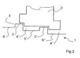
- Fig. 3 shows a two-stage connecting flange 2.
- a gap 4, 4 ', 4 " is provided in each case in front of and behind the joints 3, 3'.
- the gap 4 ' into which material softened during friction welding penetrates from both joints 3, 3', is dimensioned with regard to its height and length in that the material displaced from the joint 3 does not hinder the flow of material from the joint 3 '
- the two-stage connection flange 2 of the hub part has no undercuts in the radial direction in this embodiment, the undercuts 9, 9' necessary for the formation of the joints 3, 3 '. , 9 "are all mounted on the shaft 1.
- the joint structure according to the invention is e.g. used in the connection of a crankshaft with a drive wheel.
- a one-piece hub unit comprising the hub part of the drive wheel and the connecting flange is first produced.
- a defined gap is introduced in front of and behind the intended joint, which impedes the material softened during subsequent joining of crankshaft and connecting flange by friction welding in its propagation.
- a stepped tool is used, so that the internal machining of the hub is performed by means of a single tool in a single process step.
- the drive wheel may be cooled to prevent, for example, starting a hardened toothing provided on the drive wheel during friction welding.
Landscapes
- Engineering & Computer Science (AREA)
- General Engineering & Computer Science (AREA)
- Mechanical Engineering (AREA)
- Ocean & Marine Engineering (AREA)
- Pressure Welding/Diffusion-Bonding (AREA)
Applications Claiming Priority (2)
| Application Number | Priority Date | Filing Date | Title |
|---|---|---|---|
| DE10336668A DE10336668A1 (de) | 2003-08-09 | 2003-08-09 | Fügestellenstruktur für ein Reibschweißverfahren und Verfahren zu deren Herstellung |
| PCT/EP2004/008490 WO2005014222A1 (de) | 2003-08-09 | 2004-07-29 | Fügestellenstruktur für ein reibschweissverfahren und verfahren zu deren herstellung |
Publications (2)
| Publication Number | Publication Date |
|---|---|
| EP1651379A1 EP1651379A1 (de) | 2006-05-03 |
| EP1651379B1 true EP1651379B1 (de) | 2010-09-08 |
Family
ID=34089147
Family Applications (1)
| Application Number | Title | Priority Date | Filing Date |
|---|---|---|---|
| EP04763595A Expired - Lifetime EP1651379B1 (de) | 2003-08-09 | 2004-07-29 | Fügestellenstruktur für ein reibschweissverfahren und verfahren zum fügen |
Country Status (5)
| Country | Link |
|---|---|
| US (1) | US20070284407A1 (https=) |
| EP (1) | EP1651379B1 (https=) |
| JP (1) | JP2007533456A (https=) |
| DE (2) | DE10336668A1 (https=) |
| WO (1) | WO2005014222A1 (https=) |
Families Citing this family (6)
| Publication number | Priority date | Publication date | Assignee | Title |
|---|---|---|---|---|
| DE202005000430U1 (de) * | 2005-01-13 | 2006-05-24 | Brose Fahrzeugteile Gmbh & Co. Kommanditgesellschaft, Coburg | Befestigung eines Getriebeelementes in einem Kraftfahrzeug |
| DE102008044087A1 (de) * | 2008-11-26 | 2010-05-27 | Airbus Deutschland Gmbh | Verfahren zum Herstellen von Überlappungsstoßschweißverbindungen und Überlappungsstoßschweißverbindung |
| DE102008064267A1 (de) | 2008-12-20 | 2009-08-27 | Daimler Ag | Reibverschweißte Hohlwelle für Getriebe insbesondere von Kraftfahrzeugen |
| DE102013008658A1 (de) | 2013-05-18 | 2014-03-27 | Daimler Ag | Antriebselement mit einem Kegelrad für einen Kraftwagen sowie Verfahren zum Herstellen eines solchen Antriebselements |
| GB201519805D0 (en) * | 2015-11-10 | 2015-12-23 | Rolls Royce Plc | Rotary friction welding |
| DE102016005464A1 (de) | 2016-05-06 | 2017-11-09 | lFA-Technologies GmbH | Fügestellenstruktur für durch Reibschweißen zu verbindende Bauteile und Verfahren zum Verbinden von Bauteilen durch Reibschweißen |
Family Cites Families (12)
| Publication number | Priority date | Publication date | Assignee | Title |
|---|---|---|---|---|
| GB1475678A (en) * | 1974-09-03 | 1977-06-01 | Woodhouse Rixson Ltd | Excavator bucket pivot pins |
| JPS6023913B2 (ja) * | 1982-07-02 | 1985-06-10 | 信光金属工業株式会社 | ロ−ラ |
| SE459680B (sv) * | 1984-10-01 | 1989-07-24 | Santrade Ltd | Borrstaal |
| US5037251A (en) * | 1989-03-24 | 1991-08-06 | Roth Alfred C | Thread tap |
| DE4022447C2 (de) * | 1990-07-14 | 1994-02-03 | Hemscheidt Maschf Hermann | Verfahren zum Herstellen einer Kolbenzylinderanordnung sowie Kolbenzylinderanordnung |
| AU670373B2 (en) * | 1993-06-30 | 1996-07-11 | Nitto Kohki Co., Ltd. | Annular cutter connecting apparatus and annular cutter |
| US5624214A (en) * | 1995-12-15 | 1997-04-29 | Carroll; Stuart | Adjustable drill bit extension |
| US5957634A (en) * | 1997-03-07 | 1999-09-28 | Carpinetti; David J. | Quick change drill extender system |
| DE29905633U1 (de) * | 1999-03-31 | 2000-08-10 | KUKA Schweissanlagen GmbH, 86165 Augsburg | Bauteilvorbereitung für eine Reibschweißverbindung |
| EP1066902A3 (en) * | 1999-06-30 | 2002-10-09 | Nicotec Co., Ltd. | Separation type hole saw |
| DE19934855C1 (de) * | 1999-07-24 | 2000-11-09 | Daimler Chrysler Ag | Reibgeschweißtes Welle-Scheibe-Verbundwerkstück und Verfahren zu seiner Herstellung |
| JP2004138209A (ja) * | 2002-10-21 | 2004-05-13 | Daihatsu Motor Co Ltd | 無段変速機用プーリ |
-
2003
- 2003-08-09 DE DE10336668A patent/DE10336668A1/de not_active Withdrawn
-
2004
- 2004-07-29 US US10/567,656 patent/US20070284407A1/en not_active Abandoned
- 2004-07-29 WO PCT/EP2004/008490 patent/WO2005014222A1/de not_active Ceased
- 2004-07-29 EP EP04763595A patent/EP1651379B1/de not_active Expired - Lifetime
- 2004-07-29 JP JP2006522933A patent/JP2007533456A/ja active Pending
- 2004-07-29 DE DE502004011643T patent/DE502004011643D1/de not_active Expired - Lifetime
Also Published As
| Publication number | Publication date |
|---|---|
| JP2007533456A (ja) | 2007-11-22 |
| WO2005014222A1 (de) | 2005-02-17 |
| DE502004011643D1 (de) | 2010-10-21 |
| DE10336668A1 (de) | 2005-02-24 |
| US20070284407A1 (en) | 2007-12-13 |
| EP1651379A1 (de) | 2006-05-03 |
Similar Documents
| Publication | Publication Date | Title |
|---|---|---|
| EP3241642B1 (de) | Durch aufgleitendes reibschweissen zu verbindende bauteile mit einer fügestellenstruktur und verfahren zum verbinden von bauteilen durch reibschweissen | |
| EP2603348A1 (de) | Verfahren zur herstellung eines kolbens für einen verbrennungsmotor sowie kolben für einen verbrennungsmotor | |
| DE1627594A1 (de) | Reibungsschweissverfahren und reibungsgeschweisste Antriebswelle oder Antriebsachse | |
| DE112014000490T5 (de) | Fügestellenkonstruktion, die eine Nabe und eine Welle oder ein Zahnrad, die reibverschweisst sind, umfasst | |
| DE102012205410A1 (de) | Bremsscheibenanordnung für Scheibenbremsen | |
| DE19853798C1 (de) | Einrichtung zum Verbinden eines Wellenteiles mit einer Hülse | |
| EP2603347B1 (de) | Kolben für einen verbrennungsmotor und verfahren zu seiner herstellung | |
| DE10209168B4 (de) | Stahlkolben mit Kühlkanal | |
| EP1651379B1 (de) | Fügestellenstruktur für ein reibschweissverfahren und verfahren zum fügen | |
| DE4011498A1 (de) | Kupplungsscheibe mit einer mehrteiligen nabe | |
| DE10031878A1 (de) | Element mit Innenzahnung, Verfahren und Vorrichtung zum Formen eines Elements mit Innenzahnung | |
| DE69300431T2 (de) | Viskositätsbypasskupplung für Drehmomentwandler. | |
| EP1930595A2 (de) | Förderaggregat | |
| DE102006012031A1 (de) | Verfahren zur Herstellung einer Gelenkanbindung und Gelenkanbindung | |
| DE10306697A1 (de) | Verfahren zum Schweißverbinden von Kunststoffteilen mit Hilfe von Laserstrahlung | |
| DE19515180C2 (de) | Gebaute Welle zur Kraftübertragung | |
| DE102017203433A1 (de) | Verfahren zur Herstellung eines Kolbens | |
| DE102015203078A1 (de) | Fahrwerksaktuatorvorrichtung, insbesondere Wankstabilisator | |
| EP1240439B1 (de) | Ring zur drehmomentübertragung und axialen sicherung zweier rotierender bauteile | |
| DE4338163C2 (de) | Flüssigkeitsreibungskupplung mit Verdrehsicherung | |
| DE102015219855A1 (de) | Hohlrad mit Innenverzahnung und Kronenverzahnung, sowie Verfahren zu dessen Herstellung und Schaltgetriebe mit solchem Hohlrad | |
| EP1967763A1 (de) | Mitnehmerscheiben und Verfahren zu deren Herstellung | |
| EP3507479A1 (de) | Kolben, bestehend aus einem innenteil und einem aussenteil | |
| DE102005026505A1 (de) | Verfahren zum Verbinden von zwei Bauelementen mittels Reibschweißen sowie Schweißverbindung | |
| DE10239419A1 (de) | Gehäuseanordnung für eine Reibungskupplung |
Legal Events
| Date | Code | Title | Description |
|---|---|---|---|
| PUAI | Public reference made under article 153(3) epc to a published international application that has entered the european phase |
Free format text: ORIGINAL CODE: 0009012 |
|
| 17P | Request for examination filed |
Effective date: 20060117 |
|
| AK | Designated contracting states |
Kind code of ref document: A1 Designated state(s): DE FR |
|
| DAX | Request for extension of the european patent (deleted) | ||
| RBV | Designated contracting states (corrected) |
Designated state(s): DE FR |
|
| RAP1 | Party data changed (applicant data changed or rights of an application transferred) |
Owner name: DAIMLERCHRYSLER AG |
|
| 17Q | First examination report despatched |
Effective date: 20071113 |
|
| RAP1 | Party data changed (applicant data changed or rights of an application transferred) |
Owner name: DAIMLER AG |
|
| RTI1 | Title (correction) |
Free format text: JOINT-SITE STRUCTURE FOR A FRICTION WELDING METHOD AND WELDING METHOD |
|
| GRAP | Despatch of communication of intention to grant a patent |
Free format text: ORIGINAL CODE: EPIDOSNIGR1 |
|
| GRAS | Grant fee paid |
Free format text: ORIGINAL CODE: EPIDOSNIGR3 |
|
| GRAA | (expected) grant |
Free format text: ORIGINAL CODE: 0009210 |
|
| AK | Designated contracting states |
Kind code of ref document: B1 Designated state(s): DE FR |
|
| REF | Corresponds to: |
Ref document number: 502004011643 Country of ref document: DE Date of ref document: 20101021 Kind code of ref document: P |
|
| PLBE | No opposition filed within time limit |
Free format text: ORIGINAL CODE: 0009261 |
|
| STAA | Information on the status of an ep patent application or granted ep patent |
Free format text: STATUS: NO OPPOSITION FILED WITHIN TIME LIMIT |
|
| 26N | No opposition filed |
Effective date: 20110609 |
|
| REG | Reference to a national code |
Ref country code: DE Ref legal event code: R097 Ref document number: 502004011643 Country of ref document: DE Effective date: 20110609 Ref country code: DE Ref legal event code: R082 Ref document number: 502004011643 Country of ref document: DE |
|
| REG | Reference to a national code |
Ref country code: DE Ref legal event code: R081 Ref document number: 502004011643 Country of ref document: DE Owner name: JUTZ, BERNHARD, DIPL.-ING.(FH), DE Free format text: FORMER OWNER: DAIMLER AG, 70327 STUTTGART, DE Effective date: 20111013 |
|
| REG | Reference to a national code |
Ref country code: FR Ref legal event code: ST Effective date: 20120330 |
|
| PG25 | Lapsed in a contracting state [announced via postgrant information from national office to epo] |
Ref country code: FR Free format text: LAPSE BECAUSE OF NON-PAYMENT OF DUE FEES Effective date: 20110801 |
|
| PGFP | Annual fee paid to national office [announced via postgrant information from national office to epo] |
Ref country code: DE Payment date: 20120801 Year of fee payment: 9 |
|
| PG25 | Lapsed in a contracting state [announced via postgrant information from national office to epo] |
Ref country code: DE Free format text: LAPSE BECAUSE OF NON-PAYMENT OF DUE FEES Effective date: 20140201 |
|
| REG | Reference to a national code |
Ref country code: DE Ref legal event code: R119 Ref document number: 502004011643 Country of ref document: DE Effective date: 20140201 |