EP1651007A2 - Mehrkanaltonwiedergabeanordnung und Mehrkanaltoneinstellungsverfahren - Google Patents
Mehrkanaltonwiedergabeanordnung und Mehrkanaltoneinstellungsverfahren Download PDFInfo
- Publication number
- EP1651007A2 EP1651007A2 EP05022791A EP05022791A EP1651007A2 EP 1651007 A2 EP1651007 A2 EP 1651007A2 EP 05022791 A EP05022791 A EP 05022791A EP 05022791 A EP05022791 A EP 05022791A EP 1651007 A2 EP1651007 A2 EP 1651007A2
- Authority
- EP
- European Patent Office
- Prior art keywords
- loudspeaker
- sound
- test
- section
- multichannel
- Prior art date
- Legal status (The legal status is an assumption and is not a legal conclusion. Google has not performed a legal analysis and makes no representation as to the accuracy of the status listed.)
- Withdrawn
Links
Images


Classifications
-
- H—ELECTRICITY
- H04—ELECTRIC COMMUNICATION TECHNIQUE
- H04S—STEREOPHONIC SYSTEMS
- H04S7/00—Indicating arrangements; Control arrangements, e.g. balance control
- H04S7/30—Control circuits for electronic adaptation of the sound field
- H04S7/301—Automatic calibration of stereophonic sound system, e.g. with test microphone
-
- H—ELECTRICITY
- H04—ELECTRIC COMMUNICATION TECHNIQUE
- H04R—LOUDSPEAKERS, MICROPHONES, GRAMOPHONE PICK-UPS OR LIKE ACOUSTIC ELECTROMECHANICAL TRANSDUCERS; ELECTRIC HEARING AIDS; PUBLIC ADDRESS SYSTEMS
- H04R2400/00—Loudspeakers
- H04R2400/01—Transducers used as a loudspeaker to generate sound aswell as a microphone to detect sound
Definitions
- the present invention relates to a multichannel sound reproduction apparatus for reproducing contents including multichannel sound data, and the like, which can be obtained through a recording medium, a network, a broadcasting system, etc.
- the technique of forming a suitable sound field by adjusting the characteristics of sound which is to be reproduced through loudspeakers, such as phase characteristics, frequency characteristics, sound pressure level, etc. has been proposed. Further, the technique of automatically performing such an adjustment has been proposed wherein a microphone is placed at a predetermined position for collecting test sounds reproduced through loudspeakers such that a user is free from complicated adjustment effort (for example, Japanese Laid-Open Patent Publication No. 2002-330499).
- the apparatus that performs automatic adjustments requires connecting a microphone, which is unnecessary for reproduction of multichannel sound, to the apparatus and placing the microphone at a predetermined position and is therefore lacking ease of use.
- An objective of the present invention is to automatically adjust the characteristics of sound which is to be reproduced without connecting a microphone to a reproduction apparatus or placing a microphone at a predetermined position.
- a test sound reproduced through any one of loudspeakers is collected by another loudspeaker or a microphone integrally provided with another loudspeaker, and the characteristics of sound which is to be reproduced are controlled based on the sound collection result.
- a multichannel sound reproduction apparatus for reproducing multichannel sound through a plurality of loudspeakers, comprising: a test sound signal output section for driving at least one loudspeaker to emit a test sound; a reception section for receiving a reception test sound signal generated according to the test sound collected by another loudspeaker or a microphone integrally provided with another loudspeaker; and a control section for controlling a multichannel sound signal which is to be output to each of the loudspeakers based on the reception test sound signal.
- the multichannel sound reproduction apparatus further comprises an input/output switching section for selectively connecting each of the loudspeakers to the test sound signal output section or the reception section, wherein the test sound is collected by the loudspeaker connected to the reception section.
- the test sound signal output section and the reception section perform emission and collection of a test sound a plurality of times while switching a loudspeaker for emitting the test sound and a loudspeaker or microphone for collecting the test sound.
- the test sound signal output section sequentially or simultaneously drives the plurality of loudspeakers to emit test sounds; and the reception section receives a reception test sound signal generated according to each of the test sounds.
- the control section includes: a delay time detection section for detecting a delay time of each of the test sounds; an interspeaker distance calculation section for calculating based on the delay time a distance between a loudspeaker which emits a test sound and a loudspeaker which collects the test sound; a loudspeaker position calculation section for calculating a two- or three-dimensional loudspeaker position of each loudspeaker based on the interspeaker distance; a listening distance calculation section for calculating a listening distance between each loudspeaker position and a predetermined listening position; and a delay time control section for controlling a delay time of a multichannel sound emitted by each loudspeaker based on the listening distance.
- control section further includes: a volume detection section for detecting a volume of a collected test sound; an output level calculation section for calculating an output level of each loudspeaker based on the detected volume and the interspeaker distance; and a volume control section for controlling based on the loudspeaker output level and the listening distance a volume of a multichannel sound which is to be emitted by each loudspeaker.
- the multichannel sound reproduction apparatus further comprises a memory section for memorizing at least one set of parameters for controlling a delay time and volume of the multichannel sound.
- the memory section memorizes a plurality of sets of parameters; and one of the plurality of sets of parameters is selected automatically or according to an user's instruction.
- the parameters are selected according to a listening time.
- the loudspeaker position calculation section is capable of setting a loudspeaker position of one or more loudspeakers in advance.
- the multichannel sound reproduction apparatus further comprises a listening position entry section through which a user enters the predetermined listening position.
- a multichannel sound adjustment method for adjusting multichannel sound reproduced through a plurality of loudspeakers comprising the steps of: emitting a test sound through at least one loudspeaker; receiving a reception test sound signal generated according to the test sound collected by another loudspeaker or a microphone integrally provided with another loudspeaker; and controlling a multichannel sound signal which is to be output to each of the loudspeakers based on the reception test sound signal.
- the step of controlling the multichannel sound signal includes controlling at least one of a delay time and volume of a multichannel sound emitted by each loudspeaker.
- the step of emitting the test sound and the step of receiving the reception test sound signal are performed a plurality of times while switching a loudspeaker for emitting the test sound and a loudspeaker or microphone for detecting the test sound.
- the step of emitting the test sound includes sequentially or simultaneously emitting test sounds through the plurality of loudspeakers; and the step of receiving the reception test sound signal includes outputting a reception test sound signal according to each of the test sounds.
- FIG. 1 is a block diagram showing the structure of principal part of a multichannel sound reproduction apparatus 101.
- a sound signal reproduction section 102 outputs to loudspeakers a sound signal input from a DVD device 201 (described later) through a characteristics control section 202.
- the sound signal reproduction section 102 also outputs a predetermined test sound signal.
- the test sound signal is, for example, an impulse signal, although the present invention is not limited thereto.
- a sound signal detection section 103 receives a sound signal (reception test sound signal) output from a loudspeaker which functions as a microphone as will be described later to detect a propagation time (delay time) of a test sound, which lasts from emission of a test sound by any loudspeaker to reception of the test sound by another loudspeaker, and the sound pressure level (volume) of the received test sound.
- Input/output switches 104 to 109 each switch the operation mode of a corresponding loudspeaker between the sound output mode and the sound input mode.
- Loudspeakers 110 to 115 are a front right loudspeaker, a center loudspeaker, a front left loudspeaker, a surround left loudspeaker, a surround right loudspeaker, and a sub-woofer loudspeaker, respectively.
- the loudspeakers 110 to 115 are connected to the input/output switches 104 to 109 by loudspeaker cables 116.
- the DVD device 201 is an example of a signal source of a multichannel sound signal and a video signal from which a video image is reproduced on a display 203.
- the signal source may be a reception device for receiving sound and video signals distributed through a network or a broadcasting system.
- the signal source may be a converter for converting a 2ch sound signal to a pseudo multichannel sound signal.
- the characteristics control section 202 controls the delay time and signal level (volume) of a sound signal input from the DVD device 201.
- An arithmetic operation section 204 calculates the position and output level of each of the loudspeakers 110 to 115 based on the propagation time and the sound pressure level detected by the sound signal detection section 103.
- the arithmetic operation section 204 notifies the characteristics control section 202 about the delay time and the signal level based on the positions and output levels of the loudspeakers 110 to 115 and a listening position entered by a user at an entry section 205.
- a memory section 206 memorizes the positions and output levels of the loudspeakers 110 to 115 and the listening position or the delay time and signal level about which the characteristics control section 202 is notified.
- the memory section 206 may memorize a plurality of sets of these information such that a set of information can be read from them according to a user's instruction or viewing time. More specifically, in the case where the listening environment of a room in which the apparatus of the present invention is installed differs with the passage of time (for example, curtains are open during the daytime but closed during the nighttime), one of a plurality of sets of information may be selected according to the listening time. With such a feature, desirable realism is automatically obtained even when the indoor listening environment differs between day and night.
- the sound signal detection section 103, the characteristics control section 202 and the arithmetic operation section 204 constitute a reception section for receiving a reception test sound signal generated according to a test sound collected by loudspeakers other than one that has emitted the test sound and a control section for controlling a multichannel sound signal which is to be output to each loudspeaker based on the reception test sound signal.
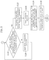
- reproduction sound is adjusted as described below and as illustrated in FIGS. 2 to FIG. 5.
- the distance between any two of the loudspeakers is measured twice.
- the two measured values may be averaged for improving the accuracy.
- the number of times of detection may be decreased.
- the directivity of the loudspeakers 110 to 115 may be considered in the calculation of the output level.
- interspeaker distances are represented by “a” to "o” as shown in FIG. 6:
- the positions where the loudspeakers are installed are represented by three-dimensional coordinates as follows:
- the positions of all the loudspeakers can be determined using 12 out of the 15 expressions shown above. Although only 12 interspeaker distances may be measured, it is possible that 15 distances are measured and, when a coordinate value does not result in one value, the error is distributed to relevant coordinates. In the case where measurement of the interspeaker distances cannot be appropriately carried out or where the arithmetic operation section 204 is set in advance to measure less than 12 interspeaker distances, a user may set the positions of some loudspeakers through, for example, the processes of steps S125 and S126 of FIG. 5.
- the information stored in the memory section 206 are not limited to the delay time and signal level themselves but may be parameters from which the delay time and signal level can be determined.
- reproduction sound signals for the loudspeakers 110 to 115 are input from the DVD device 201 to the characteristics control section 202.
- the characteristics control section 202 delays each of the reproduction sound signals according to the designated delay time and signal level corresponding thereto and converts (amplifies) the signal level.
- the resultant reproduction sound signal is output to the sound signal reproduction section 102. As a result, a sound field optimum for listening at the listening position 301 is formed.
- the positions of the loudspeakers 110 to 115 are mapped in the three-dimensional space, if the loudspeakers 110 to 115 are placed at substantially the same height, the positions of the loudspeakers 110 to 115 may be mapped in the two-dimensional space with the following coordinates, for example:
- the loudspeakers 110 to 115 are switched by the input/output switches 104 to 109 to function as microphones, but the present invention is not limited thereto.
- a microphone may be provided integrally with each of the loudspeakers 110 to 115.
- the characteristics of sound which is to be reproduced can be automatically adjusted without a necessity to connect a separate microphone to the multichannel sound reproduction apparatus or place a separate microphone at a predetermined position.
- the sound pressure level of each of the loudspeakers 110 to 115 can be detected only with a combination of each of the loudspeakers 110 to 115 and a corresponding microphone.
- the test sound signal is not limited to the impulse signal but may be a sinusoidal signal, a noise signal, a general non-periodic sound signal, or the like. Even in the case of a general sound signal, a phase difference (propagation time) can readily be detected by comparing the waveform of a signal output from the sound signal reproduction section 102 and the waveform of a signal detected by the sound signal detection section 103.
- test sounds having different frequencies may be simultaneously emitted through a plurality of loudspeakers. In this case, the time of the entire adjustment process is shortened.
- the adjustable parameters are not limited to the delay time and signal level, but only one of these parameters may be adjusted. Alternatively, the frequency characteristic, the echo, etc., may be adjustable together with, or in place of, the delay time and/or signal level.
- the present invention is applicable to various multichannel sound reproduction apparatuses capable of sound reproduction of 3 or more channels.
Landscapes
- Physics & Mathematics (AREA)
- Engineering & Computer Science (AREA)
- Acoustics & Sound (AREA)
- Signal Processing (AREA)
- Stereophonic System (AREA)
- Circuit For Audible Band Transducer (AREA)
Applications Claiming Priority (1)
| Application Number | Priority Date | Filing Date | Title |
|---|---|---|---|
| JP2004305468 | 2004-10-20 |
Publications (2)
| Publication Number | Publication Date |
|---|---|
| EP1651007A2 true EP1651007A2 (de) | 2006-04-26 |
| EP1651007A3 EP1651007A3 (de) | 2007-10-31 |
Family
ID=35645586
Family Applications (1)
| Application Number | Title | Priority Date | Filing Date |
|---|---|---|---|
| EP05022791A Withdrawn EP1651007A3 (de) | 2004-10-20 | 2005-10-19 | Mehrkanaltonwiedergabeanordnung und Mehrkanaltoneinstellungsverfahren |
Country Status (2)
| Country | Link |
|---|---|
| US (1) | US20060083391A1 (de) |
| EP (1) | EP1651007A3 (de) |
Cited By (6)
| Publication number | Priority date | Publication date | Assignee | Title |
|---|---|---|---|---|
| WO2006059299A3 (en) * | 2004-12-02 | 2009-02-19 | Koninkl Philips Electronics Nv | Position sensing using loudspeakers as microphones |
| WO2010140088A1 (en) * | 2009-06-03 | 2010-12-09 | Koninklijke Philips Electronics N.V. | Estimation of loudspeaker positions |
| EP3211921A1 (de) * | 2016-02-24 | 2017-08-30 | Onkyo Corporation | Schallfeldsteuerungssystem, steuerungsverfahren für ein schallfeldsteuerungssystem und aufzeichnungsmedium |
| WO2018210429A1 (en) * | 2017-05-19 | 2018-11-22 | Gibson Innovations Belgium Nv | Calibration system for loudspeakers |
| EP3506660A1 (de) * | 2017-12-27 | 2019-07-03 | Vestel Elektronik Sanayi ve Ticaret A.S. | Verfahren zur kalibrierung eines audiowiedergabesystems und entsprechendes audiowiedergabesystem |
| EP3557887A1 (de) * | 2018-04-12 | 2019-10-23 | Dolby Laboratories Licensing Corp. | Selbstkalibrierendes system mit mehreren niedrig-frequenz lautsprechern |
Families Citing this family (9)
| Publication number | Priority date | Publication date | Assignee | Title |
|---|---|---|---|---|
| WO2011060535A1 (en) * | 2009-11-19 | 2011-05-26 | Adamson Systems Engineering Inc. | Method and system for determining relative positions of multiple loudspeakers in a space |
| KR102081336B1 (ko) * | 2013-06-17 | 2020-02-25 | 삼성전자주식회사 | 오디오 시스템, 오디오 장치 및 오디오 장치의 채널 맵핑 방법 |
| CN103747409B (zh) * | 2013-12-31 | 2017-02-08 | 北京智谷睿拓技术服务有限公司 | 扬声装置、扬声方法及交互设备 |
| CN103702259B (zh) | 2013-12-31 | 2017-12-12 | 北京智谷睿拓技术服务有限公司 | 交互装置及交互方法 |
| US20160337755A1 (en) * | 2015-05-13 | 2016-11-17 | Paradigm Electronics Inc. | Surround speaker |
| JP6646677B2 (ja) * | 2015-10-09 | 2020-02-14 | 株式会社日立製作所 | 音声信号処理方法および装置 |
| JP7107036B2 (ja) * | 2018-07-05 | 2022-07-27 | ヤマハ株式会社 | スピーカの位置判定方法、スピーカの位置判定システム、音響装置及びプログラム |
| US10650840B1 (en) * | 2018-07-11 | 2020-05-12 | Amazon Technologies, Inc. | Echo latency estimation |
| US12058509B1 (en) * | 2021-12-09 | 2024-08-06 | Amazon Technologies, Inc. | Multi-device localization |
Family Cites Families (3)
| Publication number | Priority date | Publication date | Assignee | Title |
|---|---|---|---|---|
| JP3526680B2 (ja) * | 1995-10-27 | 2004-05-17 | 株式会社ケンウッド | ディレイタイム設定装置 |
| US20040071294A1 (en) * | 2002-10-15 | 2004-04-15 | Halgas Joseph F. | Method and apparatus for automatically configuring surround sound speaker systems |
| JP2004241820A (ja) * | 2003-02-03 | 2004-08-26 | Denon Ltd | マルチチャンネル再生装置 |
-
2005
- 2005-10-18 US US11/251,898 patent/US20060083391A1/en not_active Abandoned
- 2005-10-19 EP EP05022791A patent/EP1651007A3/de not_active Withdrawn
Cited By (12)
| Publication number | Priority date | Publication date | Assignee | Title |
|---|---|---|---|---|
| WO2006059299A3 (en) * | 2004-12-02 | 2009-02-19 | Koninkl Philips Electronics Nv | Position sensing using loudspeakers as microphones |
| US8311233B2 (en) | 2004-12-02 | 2012-11-13 | Koninklijke Philips Electronics N.V. | Position sensing using loudspeakers as microphones |
| WO2010140088A1 (en) * | 2009-06-03 | 2010-12-09 | Koninklijke Philips Electronics N.V. | Estimation of loudspeaker positions |
| CN102461214A (zh) * | 2009-06-03 | 2012-05-16 | 皇家飞利浦电子股份有限公司 | 扬声器位置的估计 |
| RU2543937C2 (ru) * | 2009-06-03 | 2015-03-10 | Конинклейке Филипс Электроникс Н.В. | Оценка положений громкоговорителей |
| CN102461214B (zh) * | 2009-06-03 | 2015-09-30 | 皇家飞利浦电子股份有限公司 | 扬声器位置的估计 |
| US9332371B2 (en) | 2009-06-03 | 2016-05-03 | Koninklijke Philips N.V. | Estimation of loudspeaker positions |
| EP3211921A1 (de) * | 2016-02-24 | 2017-08-30 | Onkyo Corporation | Schallfeldsteuerungssystem, steuerungsverfahren für ein schallfeldsteuerungssystem und aufzeichnungsmedium |
| WO2018210429A1 (en) * | 2017-05-19 | 2018-11-22 | Gibson Innovations Belgium Nv | Calibration system for loudspeakers |
| EP3506660A1 (de) * | 2017-12-27 | 2019-07-03 | Vestel Elektronik Sanayi ve Ticaret A.S. | Verfahren zur kalibrierung eines audiowiedergabesystems und entsprechendes audiowiedergabesystem |
| EP3557887A1 (de) * | 2018-04-12 | 2019-10-23 | Dolby Laboratories Licensing Corp. | Selbstkalibrierendes system mit mehreren niedrig-frequenz lautsprechern |
| US10805750B2 (en) | 2018-04-12 | 2020-10-13 | Dolby Laboratories Licensing Corporation | Self-calibrating multiple low frequency speaker system |
Also Published As
| Publication number | Publication date |
|---|---|
| EP1651007A3 (de) | 2007-10-31 |
| US20060083391A1 (en) | 2006-04-20 |
Similar Documents
| Publication | Publication Date | Title |
|---|---|---|
| EP1651007A2 (de) | Mehrkanaltonwiedergabeanordnung und Mehrkanaltoneinstellungsverfahren | |
| US9380400B2 (en) | Optimizing audio systems | |
| JP5672748B2 (ja) | 音場制御装置 | |
| JP4361354B2 (ja) | 自動音場補正装置及びそのためのコンピュータプログラム | |
| AU2019222847B2 (en) | Audio adaptation to room | |
| JP5430242B2 (ja) | スピーカ位置検出システム及びスピーカ位置検出方法 | |
| DK2839678T3 (en) | Audio system optimization | |
| JP2003255955A (ja) | 音場制御方法及び音場制御システム | |
| CN101438604A (zh) | 使用扬声器作为麦克风的位置感知 | |
| JP4240232B2 (ja) | テストトーンの判定方法および音場補正装置 | |
| US20100208903A1 (en) | Audio module for the acoustic monitoring of a surveillance region, surveillance system for the surveillance region, method for generating a sound environment, and computer program | |
| JP2006148880A (ja) | マルチチャネル音声再生装置、およびマルチチャネル音声調整方法 | |
| JP4283645B2 (ja) | 信号遅延時間測定装置及びそのためのコンピュータプログラム | |
| JP4184420B2 (ja) | 特性測定装置及び特性測定プログラム | |
| JP4376035B2 (ja) | 音響特性測定装置及び自動音場補正装置並びに音響特性測定方法及び自動音場補正方法 | |
| EP2208369A2 (de) | Tonprojektoreinstellung | |
| JP6056842B2 (ja) | 音場制御装置 | |
| JP4096958B2 (ja) | スピーカアレイ装置 | |
| JP6466251B2 (ja) | 音場再現システム | |
| JP4096960B2 (ja) | スピーカアレイ装置 | |
| WO2023025695A1 (en) | Method of calculating an audio calibration profile | |
| JP2011199795A (ja) | 放音システムおよびavシステム | |
| JP4096959B2 (ja) | スピーカアレイ装置 | |
| JP4797539B2 (ja) | 音響システム | |
| JP2011233997A (ja) | オーディオ再生装置 |
Legal Events
| Date | Code | Title | Description |
|---|---|---|---|
| PUAI | Public reference made under article 153(3) epc to a published international application that has entered the european phase |
Free format text: ORIGINAL CODE: 0009012 |
|
| AK | Designated contracting states |
Kind code of ref document: A2 Designated state(s): AT BE BG CH CY CZ DE DK EE ES FI FR GB GR HU IE IS IT LI LT LU LV MC NL PL PT RO SE SI SK TR |
|
| AX | Request for extension of the european patent |
Extension state: AL BA HR MK YU |
|
| PUAL | Search report despatched |
Free format text: ORIGINAL CODE: 0009013 |
|
| AK | Designated contracting states |
Kind code of ref document: A3 Designated state(s): AT BE BG CH CY CZ DE DK EE ES FI FR GB GR HU IE IS IT LI LT LU LV MC NL PL PT RO SE SI SK TR |
|
| AX | Request for extension of the european patent |
Extension state: AL BA HR MK YU |
|
| RIC1 | Information provided on ipc code assigned before grant |
Ipc: H04S 7/00 20060101ALI20070927BHEP Ipc: H04S 3/00 20060101AFI20060131BHEP |
|
| AKX | Designation fees paid | ||
| STAA | Information on the status of an ep patent application or granted ep patent |
Free format text: STATUS: THE APPLICATION HAS BEEN WITHDRAWN |
|
| 18W | Application withdrawn |
Effective date: 20080703 |
|
| REG | Reference to a national code |
Ref country code: DE Ref legal event code: 8566 |