EP1650385B1 - Scharniergelenk - Google Patents
Scharniergelenk Download PDFInfo
- Publication number
- EP1650385B1 EP1650385B1 EP05022548.1A EP05022548A EP1650385B1 EP 1650385 B1 EP1650385 B1 EP 1650385B1 EP 05022548 A EP05022548 A EP 05022548A EP 1650385 B1 EP1650385 B1 EP 1650385B1
- Authority
- EP
- European Patent Office
- Prior art keywords
- plate
- hinge
- joint part
- joint
- sleeve
- Prior art date
- Legal status (The legal status is an assumption and is not a legal conclusion. Google has not performed a legal analysis and makes no representation as to the accuracy of the status listed.)
- Expired - Lifetime
Links
Images


Classifications
-
- H—ELECTRICITY
- H02—GENERATION; CONVERSION OR DISTRIBUTION OF ELECTRIC POWER
- H02B—BOARDS, SUBSTATIONS OR SWITCHING ARRANGEMENTS FOR THE SUPPLY OR DISTRIBUTION OF ELECTRIC POWER
- H02B1/00—Frameworks, boards, panels, desks, casings; Details of substations or switching arrangements
- H02B1/26—Casings; Parts thereof or accessories therefor
- H02B1/40—Wall-mounted casings; Parts thereof or accessories therefor
- H02B1/44—Hinged covers or doors
-
- E—FIXED CONSTRUCTIONS
- E05—LOCKS; KEYS; WINDOW OR DOOR FITTINGS; SAFES
- E05D—HINGES OR SUSPENSION DEVICES FOR DOORS, WINDOWS OR WINGS
- E05D7/00—Hinges or pivots of special construction
- E05D7/10—Hinges or pivots of special construction to allow easy separation or connection of the parts at the hinge axis
- E05D7/1044—Hinges or pivots of special construction to allow easy separation or connection of the parts at the hinge axis in an axial direction
- E05D7/105—Hinges or pivots of special construction to allow easy separation or connection of the parts at the hinge axis in an axial direction requiring a specific angular position
-
- E—FIXED CONSTRUCTIONS
- E05—LOCKS; KEYS; WINDOW OR DOOR FITTINGS; SAFES
- E05Y—INDEXING SCHEME ASSOCIATED WITH SUBCLASSES E05D AND E05F, RELATING TO CONSTRUCTION ELEMENTS, ELECTRIC CONTROL, POWER SUPPLY, POWER SIGNAL OR TRANSMISSION, USER INTERFACES, MOUNTING OR COUPLING, DETAILS, ACCESSORIES, AUXILIARY OPERATIONS NOT OTHERWISE PROVIDED FOR, APPLICATION THEREOF
- E05Y2900/00—Application of doors, windows, wings or fittings thereof
- E05Y2900/20—Application of doors, windows, wings or fittings thereof for furniture, e.g. cabinets
- E05Y2900/208—Application of doors, windows, wings or fittings thereof for furniture, e.g. cabinets for metal cabinets
Definitions
- the invention relates to a hinge joint, in particular for the connection of a cover of an electrical distributor with a hinged cover closing the cover, with a first hinge part having a plate-shaped portion, and a second hinge part pivotable to the first hinge part, wherein the first hinge part mif connected to a Gelenkachsbolzen which is rigidly connected to at least one end at the edge of a peripheral recess formed in the plate-shaped portion with the plate-shaped portion and which spans the edge recess, and the second hinge part with a pivotable on the Gelenkochsbolzen sleeve having a longitudinal slot and the Gelenkachsbolzen engages over part of its circumference, is connected.
- Such a hinge joint goes out of the WO 82/03421 A1 out.
- a bead forming in the hinge pin is formed, which can be inserted into a bearing provided by a second joint part.
- the bearing is projected by a right-angled plate member and by the plate member.
- Formed hooks which engage in movement of the two joint parts against each other by provided in the first joint part adjacent to the bead recesses.
- a hinge assembly for pivotally connecting a lid to the housing of an image scanner comprises hooks with a bearing shell arranged at its distal end, which has a cylindrical bearing recess for receiving a hinge pin, which forms a second hinge part.
- the hinge pin is mounted on bearing blocks on the housing of the image scanner and spaced at the image scanner and has a portion in which the hinge pin is flattened laterally so that it has a reduced width. The width of the flattened portion is smaller than a recess in a peripheral wall of the bearing shell, so that the hinge pin is inserted through the slot in the bearing shell.
- the invention has for its object to provide a hinge joint of the type mentioned, which can be assembled with little effort.
- this object is achieved in that the plate thickness of the plate-shaped portion is reduced in an adjacent to the hinge pin edge region such that it is smaller than the width of the longitudinal slot, so that the sleeve for mounting under engagement of the plate-shaped portion in the longitudinal slot of the sleeve in Direction parallel to the plate-shaped portion and perpendicular to the edge region of the plate-shaped portion can be plugged onto the edge region and is displaceable in the attached state of the edge region on the Gelenkachsbolzen.
- the axle is offset from the median plane of the plate-shaped portion, e.g. such that the axis of rotation coincides with the surface of the plate-shaped portion.
- the sleeve may be rigidly connected to a plate-shaped portion of the second joint part, wherein optionally also the axis of the sleeve is offset from the median plane of this plate-shaped portion.
- the plate-shaped portion of the second hinge part can be connectable to the cover via a bolt used to fasten the cover to the distributor.
- the bolt fulfills a dual function in this case.
- a cover 1 for an electrical distributor is connected via hinge joints 2 with a hinged lid 3, through which the front side of the cover 1 can be closed.
- the provided with a handle 4 hinged lid 3 snaps on the cover 1 releasably.
- the hinge joints 2 each have a first hinge part 5, which is formed on a Randabwinklung 6 of the hinged lid 3.
- the bolt 8 with a head 9 is inserted into a guide shaft 10 integrally connected to the cover 1 and has a passage 11 for a sealing wire.
- first joint part 5 has a plate-shaped portion 12 formed by the bend 6 with a peripheral recess 13 which is spanned by a at both ends rigidly connected to the edge of the recess 13, circular in cross-section hinge axle bolt 14.
- an edge region 15 is provided in the plate-shaped portion 12, in which the plate thickness is reduced and a rounded edge portion 16 is formed.
- Fig. 3 can recognize, the second hinge part 7 a sleeve portion 17 and an integrally connected to the sleeve portion 17, approximately plate-shaped portion 18.
- the sleeve portion 17 is provided with a longitudinal slot 19.
- the plate-shaped portion 18 has a passage opening 20 with a recess 21, which forms a seat for the head 9 of the fastening bolt 8.
- diametrically opposed passages 22 serve to receive the passage 11 of the bolt head 9 passing through the sealing wire.
- the second hinge part 7 is attached to the reduced in thickness edge region 15 of the first joint part 5, wherein the second joint part of the in Fig. 6 shown pivot position occupies.
- the second joint part 7 can now be moved in the direction of the hinge axle bolt 14 as shown in arrow 23 and pushed onto the hinge axle bolt 14 as far as a stop 24.
- the peripheral recess 13 provides clearance for pivoting the second joint part 7.
- the Gelenkachsbolzen 14 is offset from the median plane of the plate-shaped portion 12 of the joint part 5 such that a pivoting of the hinged lid 3 by 180 ° is possible.
- the bolts 8 fulfill in the embodiment shown a dual function by one hand, the cover 1 on the distributor and on the other hand, the second hinge parts 7 held on the cover.
- Plombierdraht which is guided through the passage opening 22, there is also a seal of the hinged lid.
Landscapes
- Engineering & Computer Science (AREA)
- Mechanical Engineering (AREA)
- Power Engineering (AREA)
- Connections Effected By Soldering, Adhesion, Or Permanent Deformation (AREA)
- Pivots And Pivotal Connections (AREA)
Description
- Die Erfindung betrifft ein Scharniergelenk, insbesondere für die Verbindung einer Abdeckung eines elektrischen Verteilers mit einem die Abdeckung verschließenden Klappdeckel, mit einem ersten Gelenkteil, der einen plattenförmigen Abschnitt aufweist, und einem zu dem ersten Gelenkteil schwenkbeweglichen zweiten Gelenkteil, wobei dererste Gelenkteil mif einem Gelenkachsbolzen verbunden ist, welcher mit wenigstens einem Ende am Rand einer Randaussparung, die in dem plattenförmigen Abschnitt gebildet ist, starr mit dem plattenförmigen Abschnitt verbunden ist und welcher die Randaussparung überspannt, und der zweite Gelenkteil mit einer auf dem Gelenkochsbolzen drehbaren Hülse, die einen Längsschlitz aufweist und den Gelenkachsbolzen über einen Teil seines Umfangs umgreift, verbunden ist.
- Ein solches Scharniergelenk geht aus der
WO 82/03421 A1 - Ein weiteres Scharniergelenk ist aus der
US 3,243,503 bekannt, die ein Kabelgehäuse mit einem Deckel beschreibt, der an seinen über das Gehäuse greifenden Abkantungen mit Schlitzen versehen ist, in die ein halbzylindrischer Teil eines außen an dem Gehäuse befestigten Scharnierteils eingreift. - Aus der
DE 40 34 959 A1 ist eine Scharnieranordnung zur schwenkbaren Verbindung eines Deckels mit dem Gehäuse eines Bildscanners bekannt. Ein an dem Deckel vorgesehener Gelenkteil umfasst Haken mit einer an seinem distalen Ende angeordneten Lagerschale, die eine zylindrische Lagerausnehmung zur Aufnahme eines Scharnierbolzens aufweist, der einen zweiten Gelenkteil bildet. Der Scharnierbolzen ist über Lagerböcke an dem Gehäuse des Bildscanners befestigt und im Abstand an dem Bildscanner gehalten und weist einen Abschnitt auf, in dem der Scharnierbolzen seitlich abgeflacht ist, sodass er eine verringerte Breite aufweist. Die Breite des abgeflachten Abschnitts ist kleiner als eine Ausnehmung in einer Umfangswand der Lagerschale, sodass der Scharnierbolzen durch den Schlitz in die Lagerschale einführbar ist. - Ein weiteres Scharniergelenk geht aus der
DE 299 04 321 hervor. - Ferner sind zweiteilige Scharniergelenke durch Benutzung bekannt.
- Der Erfindung liegt die Aufgabe zugrunde, ein Scharniergelenk der eingangs genannten Art zu schaffen, das sich mit geringem Arbeitsaufwand montieren lässt.
- Erfindungsgemäß wird diese Aufgabe dadurch gelöst, dass die Plattendicke des plattenförmigen Abschnitts in einem an den Gelenkbolzen angrenzenden Randbereich derart verringert ist, dass sie kleiner als die Breite des Längsschlitzes ist, sodass die Hülse zur Montage unter Eingriff des plattenförmigen Abschnitts in den Längsschlitz der Hülse in Richtung parallel zu dem plattenförmigen Abschnitt und senkrecht zu dem Randbereich des plattenförmigen Abschnitts auf den Randbereich aufsteckbar ist und im aufgesteckten Zustand von dem Randbereich auf den Gelenkachsbolzen verschiebbar ist.
- Zweckmäßig ist ein die Verschiebung begrenzender Anschlag vorgesehen.
- In weiterer Ausgestaltung der Erfindung ist der Achsbolzen versetzt zur Mittelebene des plattenförmigen Abschnitts angeordnet, z.B. derart, dass die Drehachse mit der Oberfläche des plattenförmigen Abschnitts zusammenfällt.
- Auf diese Weise lässt sich ein weiter Schwenkbereich, insbesondere eine Schwenkwinkel um 180°, erreichen.
- Die Hülse kann starr mit einem plattenförmigen Abschnitt des zweiten Gelenkteils verbunden sein, wobei ggf. auch die Achse der Hülse versetzt zur Mittelebene dieses plattenförmigen Abschnitts angeordnet ist.
- In einer Ausführungsform der Erfindung kann der plattenförmige Abschnitt des zweiten Gelenkteils über einen zur Befestigung der Abdeckung an dem Verteiler dienenden Bolzen mit der Abdeckung verbindbar sein. Vorteilhaft erfüllt der Bolzen in diesem Fall eine Doppelfunktion.
- Die Erfindung wird nachfolgend anhand eines Ausführungsbeispiels und der beiliegenden, sich auf dieses Ausführungsbeispiel beziehenden Zeichnungen näher erläutert. Es zeigen:
- Fig. 1
- eine Abdeckung eines elektrischen Verteilers, welche über Scharniergelenke nach der Erfindung mit einem Klappdeckel verbunden ist,
- Fig. 2
- den von der Abdeckung abgenommenen Klappdeckel von
Fig. 1 , - Fig. 3
- ein Gelenkteil der Scharniergelenke in verschiedenen perspektivischen Darstellungen,
- Fig. 4 eine
- Teilansicht der Abdeckung mit dem Klappdeckel von
Fig. 1 , welche einen Schnitt durch eines der Scharniergelenke nach der Erfindung zeigt, - Fig. 5 ein
- weiteres Gelenkteil zeigende Teilansichten des Klappdeckels von
Fig. 1 in verschiedenen perspektivischen Darstellungen, und - Fig. 6 und 7
- die Montage eines Scharniergelenks nach der Erfindung erläuternde Darstellungen.
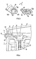
- Eine Abdeckung 1 für einen elektrischen Verteiler ist über Scharniergelenke 2 mit einem Klappdeckel 3 verbunden, durch welchen die Frontseite der Abdeckung 1 verschließbar ist. Der mit einem Griff 4 versehene Klappdeckel 3 rastet an der Abdeckung 1 lösbar ein.
- Die Scharniergelenke 2 weisen jeweils einen ersten Gelenkteil 5 auf, welcher an einer Randabwinklung 6 des Klappdeckels 3 gebildet ist.
- Mit dem ersten Gelenkteil 5 schwenkbeweglich verbindbar ist ein zweiter Gelenkteil 7, welcher über einen Bolzen 8, welcher ferner der Befestigung der Abdeckung 1 am Verteiler dient, mit der Abdeckung 1 verbunden ist, wie insbesondere
Fig. 4 erkennen lässt. Der Bolzen 8 mit einem Kopf 9 ist in einen einstückig mit der Abdeckung 1 verbundenen Führungsschacht 10 eingeführt und weist einen Durchgang 11 für einen Plombierdraht auf. - Der in
Fig. 5 gesondert dargestellte erste Gelenkteil 5 weist einen durch die Abwinklung 6 gebildeten plattenförmigen Abschnitt 12 mit einer Randaussparung 13 auf, welche von einem an beiden Enden starr mit dem Rand der Aussparung 13 verbundenen, im Querschnitt kreisrunden Gelenkachsbolzen 14 überspannt ist. - Angrenzend an den einstückig an den plattenförmigen Abschnitt 12 angeformten Gelenkachsbolzen 14 bzw. an die Randaussparung 13 ist in dem plattenförmigen Abschnitt 12 ein Randbereich 15 vorgesehen, in welchem die Plattendicke verringert und ein abgerundeter Randbereich 16 gebildet ist.
- Wie insbesondere
Fig. 3 erkennen lässt, weist der zweite Gelenkteil 7 einen Hülsenabschnitt 17 und einen mit dem Hülsenabschnitt 17 einstückig verbundenen, etwa plattenförmigen Abschnitt 18 auf. - Der Hülsenabschnitt 17 ist mit einem Längsschlitz 19 versehen. Der plattenförmige Abschnitt 18 weist eine Durchgangsöffnung 20 mit einer Einsenkung 21 auf, welche einen Sitz für den Kopf 9 des Befestigungsbolzens 8 bildet. An der Einsenkung 21 einander diametral gegenüberliegende Durchgänge 22 dienen der Aufnahme des den Durchgang 11 des Bolzenkopfs 9 durchsetzenden Plombierdrahts.
- Zur Montage der Scharniergelenke wird gemäß
Fig. 6 der zweite Gelenkteil 7 auf den in der Dicke verringerten Randbereich 15 des ersten Gelenkteils 5 aufgesteckt, wobei der zweite Gelenkteil die inFig. 6 gezeigte Schwenkposition einnimmt. Der zweite Gelenkteil 7 lässt sich nun gemäß Pfeil 23 in Richtung zu dem Gelenkachsbolzen 14 bewegen und auf den Gelenkachsbolzen 14 bis zu einem Anschlag 24 aufschieben. In der aufgeschobenen Position bietet die Randausnehmung 13 Freiraum zur Verschwenkung des zweiten Gelenkteils 7. - Wie
Fig. 4 erkennen lässt, ist in der geschlossenen Position des Klappdeckels 3 der Längsschlitz 19 des Hülsenabschnitts 17 des zweiten Gelenkteils 7 durch die Abdeckung 1 verschlossen. - Der Gelenkachsbolzen 14 ist zur Mittelebene des plattenförmigen Abschnitts 12 des Gelenkteils 5 derart versetzt angeordnet, dass eine Verschwenkung des Klappdeckels 3 um 180° möglich ist.
- Die Anschläge 24 der beiden in
Fig. 1 gezeigten Scharniergelenke 2, welche zueinander spiegelbildlich angeordnet sind, verhindern, dass sich der Klappdeckel 3 in Richtung der Gelenkachse verschieben lässt, wenn der Längsschlitz 19 in einer Schwenkstellung zu dem plattenförmigen Abschnitt 12 ausgerichtet ist. - Die Bolzen 8 erfüllen in dem gezeigten Ausführungsbeispiel eine Doppelfunktion, indem sie einerseits die Abdeckung 1 am Verteiler und andererseits die zweiten Gelenkteile 7 an der Abdeckung festgehalten. Durch den Plombierdraht, welcher durch die Durchgangsöffnung 22 geführt ist, erfolgt auch eine Plombierung des Klappdeckels.
Claims (6)
- Scharniergelenk, insbesondere für die Verbindung einer Abdeckung (1) eines elektrischen Verteilers mit einem die Abdeckung verschließenden Klappdeckel (3), mit einem ersten Gelenkteil (5), der einen plattenförmigen Abschnitt (12) aufweist, und einem zu dem ersten Gelenkteil (5) schwenkbeweglichen zweiten Gelenkteil (7), wobei der erste Gelenkteil (5) mit einem Gelenkachsbolzen (14) verbunden ist, welcher mit wenigstens einem Ende am Rand einer Randaussparung (13), die in dem plattenförmigen Abschnitt (12) gebildet ist, starr mit dem plattenförmigen Abschnitt (12) verbunden ist und welcher die Randaussparung (13) überspannt, und der zweite Gelenkteil (7) mit einer auf dem Gelenkachsbolzen (14) drehbaren Hülse (17), die einen Längsschlitz (19) aufweist und den Gelenkachsbolzen (14) über einen Teil seines Umfangs umgreift, verbunden ist,
dadurch gekennzeichnet,
dass die Plattendicke des plattenförmigen Abschnitts (12) in einem an den Gelenkachsbolzen (14) angrenzenden Randbereich derart verringert ist, dass sie kleiner als die Breite des Längsschlitzes (19) ist, sodass die Hülse (17) zur Montage unter Eingriff des plattenförmigen Abschnitts (12) in den Längsschlitz (19) der Hülse (17) in Richtung parallel zu dem plattenförmigen Abschnitt (12) und senkrecht zu dem Randbereich (15) des plattenförmigen Abschnitts (12) auf den Randbereich (15) aufsteckbar ist und im aufgesteckten Zustand von dem Randbereich (15) auf den Gelenkachsbolzen (14) verschiebbar ist. - Scharniergelenk nach Anspruch 1,
dadurch gekennzeichnet,
dass der Gelenkachsbolzen (14) versetzt zur Mittelebene des plattenförmigen Abschnitts (12) angeordnet ist. - Scharniergelenk nach Anspruch 1 oder 2,
dadurch gekennzeichnet,
dass der zweite Gelenkteil (7) gegen einen Anschlag (24) verschiebbar ist. - Scharniergelenk nach einem der Ansprüche 1 bis 3,
dadurch gekennzeichnet,
dass die Hülse (17) starr mit einem plattenförmigen Abschnitt (18) des zweiten Gelenkteils (7) verbunden ist. - Scharniergelenk nach Anspruch 4,
dadurch gekennzeichnet,
dass die Hülse (17) versetzt zur Mittelebene des plattenförmigen Abschnitts (18) des zweiten Gelenkteils (7) angeordnet ist. - Scharniergelenk nach Anspruch 4 oder 5,
dadurch gekennzeichnet,
dass der plattenförmige Abschnitt (18) des zweiten Gelenkteils (7) über einen der Befestigung der Abdeckung (1) an dem Verteiler dienenden Bolzen (8) mit der Abdeckung (1) verbindbar ist.
Applications Claiming Priority (1)
| Application Number | Priority Date | Filing Date | Title |
|---|---|---|---|
| DE200410051532 DE102004051532A1 (de) | 2004-10-22 | 2004-10-22 | Scharniergelenk |
Publications (3)
| Publication Number | Publication Date |
|---|---|
| EP1650385A2 EP1650385A2 (de) | 2006-04-26 |
| EP1650385A3 EP1650385A3 (de) | 2009-10-07 |
| EP1650385B1 true EP1650385B1 (de) | 2014-11-19 |
Family
ID=35781273
Family Applications (1)
| Application Number | Title | Priority Date | Filing Date |
|---|---|---|---|
| EP05022548.1A Expired - Lifetime EP1650385B1 (de) | 2004-10-22 | 2005-10-15 | Scharniergelenk |
Country Status (3)
| Country | Link |
|---|---|
| EP (1) | EP1650385B1 (de) |
| DE (1) | DE102004051532A1 (de) |
| DK (1) | DK1650385T3 (de) |
Families Citing this family (1)
| Publication number | Priority date | Publication date | Assignee | Title |
|---|---|---|---|---|
| CN110082575A (zh) * | 2019-06-13 | 2019-08-02 | 广东电网有限责任公司 | 一种计量专用单边铅封接线盒及其铅封方法 |
Citations (1)
| Publication number | Priority date | Publication date | Assignee | Title |
|---|---|---|---|---|
| WO1982003421A1 (en) * | 1981-04-02 | 1982-10-14 | Osbeck Erik | Hinge arrangement |
Family Cites Families (6)
| Publication number | Priority date | Publication date | Assignee | Title |
|---|---|---|---|---|
| US3243503A (en) | 1963-08-09 | 1966-03-29 | Hoffman Engineering Corp | Wiring trough having hinged or completely removable cover |
| DE2516596A1 (de) * | 1975-04-16 | 1976-10-28 | Bbc Brown Boveri & Cie | Elektrische steckdose insbesondere herdsteckdose mit klappdeckel |
| JP2506494Y2 (ja) | 1989-11-02 | 1996-08-07 | 旭光学工業株式会社 | イメ―ジスキャナ―のカバ―取付構造 |
| DE4413141C2 (de) * | 1994-04-19 | 2000-09-21 | Abb Patent Gmbh | Elektrisches Installationsgerät |
| DE19635712A1 (de) * | 1996-09-03 | 1998-03-05 | Hans Simon | Deckel zum Verschließen von Kästen |
| DE29904321U1 (de) | 1999-03-09 | 1999-09-23 | Marantec Antriebs- und Steuerungstechnik GmbH & Co. KG, 33428 Marienfeld | Gelenk, insbesondere zur Verbindung von Torblattlamellen |
-
2004
- 2004-10-22 DE DE200410051532 patent/DE102004051532A1/de not_active Withdrawn
-
2005
- 2005-10-15 EP EP05022548.1A patent/EP1650385B1/de not_active Expired - Lifetime
- 2005-10-15 DK DK05022548.1T patent/DK1650385T3/en active
Patent Citations (1)
| Publication number | Priority date | Publication date | Assignee | Title |
|---|---|---|---|---|
| WO1982003421A1 (en) * | 1981-04-02 | 1982-10-14 | Osbeck Erik | Hinge arrangement |
Also Published As
| Publication number | Publication date |
|---|---|
| DE102004051532A1 (de) | 2006-04-27 |
| DK1650385T3 (en) | 2015-03-02 |
| EP1650385A2 (de) | 2006-04-26 |
| EP1650385A3 (de) | 2009-10-07 |
Similar Documents
| Publication | Publication Date | Title |
|---|---|---|
| DE3343161C2 (de) | ||
| EP2424755B1 (de) | Anschlussvorrichtung zum gelenkigen verbinden eines mit einem wischarm fest verbundenen verbindungselements | |
| EP2588352B1 (de) | Anschlussvorrichtung zum gelenkigen verbinden eines wischarms mit einem wischblatt | |
| EP4232673B1 (de) | Möbelantrieb | |
| DE29922195U1 (de) | Verschluß zur Verbindung zweier dünner Wände | |
| EP1886873A1 (de) | Rastgelenk und Außenspiegel mit einem solchen Rastgelenk | |
| EP1849937A2 (de) | Klipsbefestigung für die Schnellmontage von Beschlageinrichtungen, wie Schwenkhebelverschlüsse, Scharnierteile in Durchbrüchen in einer dünnen Wand | |
| EP1916367A2 (de) | Kraftfahrzeugtürscharnier | |
| AT505840B1 (de) | Vorrichtung zum anschluss eines bandes an einen weiteren teil | |
| DE102015106919A1 (de) | Möbelscharnier mit einem Dämpfer | |
| AT409288B (de) | Möbelscharnier | |
| DE102008018738B4 (de) | Fahrzeugseitige Kupplungsbaugruppe einer Anhängerkupplung | |
| DE102005050222A1 (de) | Gelenkbeschlag für Kraftfahrzeugsitze und mit einer Ronde | |
| DE60304682T2 (de) | Scharnier für möbel | |
| EP1498314A1 (de) | Rastgelenkverbindung | |
| DE102006010853B4 (de) | Betätigungsvorrichtung für eine Feststellbremse | |
| EP2370654A1 (de) | Band zur scharniergelenkigen verbindung eines flügels an einem rahmen | |
| DE102017206589A1 (de) | Scharnieranordnung für eine Tür | |
| EP2642054A2 (de) | Türband für eine verdeckte Anordnung zwischen Türrahmen und Türflügel | |
| WO2008031617A1 (de) | Gelenkeinrichtung | |
| EP4045744B1 (de) | Beschlaganordnung | |
| EP0900904A2 (de) | Scharnier für Behälterabdeckungen | |
| EP1650385A2 (de) | Scharniergelenk | |
| DE10128405A1 (de) | Türangelanordnung für Hecktüren | |
| EP1736624A2 (de) | Getriebe für einen Panikgriff oder eine Panikstange |
Legal Events
| Date | Code | Title | Description |
|---|---|---|---|
| PUAI | Public reference made under article 153(3) epc to a published international application that has entered the european phase |
Free format text: ORIGINAL CODE: 0009012 |
|
| AK | Designated contracting states |
Kind code of ref document: A2 Designated state(s): AT BE BG CH CY CZ DE DK EE ES FI FR GB GR HU IE IS IT LI LT LU LV MC NL PL PT RO SE SI SK TR |
|
| AX | Request for extension of the european patent |
Extension state: AL BA HR MK YU |
|
| PUAL | Search report despatched |
Free format text: ORIGINAL CODE: 0009013 |
|
| AK | Designated contracting states |
Kind code of ref document: A3 Designated state(s): AT BE BG CH CY CZ DE DK EE ES FI FR GB GR HU IE IS IT LI LT LU LV MC NL PL PT RO SE SI SK TR |
|
| AX | Request for extension of the european patent |
Extension state: AL BA HR MK YU |
|
| 17P | Request for examination filed |
Effective date: 20100206 |
|
| 17Q | First examination report despatched |
Effective date: 20100316 |
|
| AKX | Designation fees paid |
Designated state(s): AT BE BG CH CY CZ DE DK EE ES FI FR GB GR HU IE IS IT LI LT LU LV MC NL PL PT RO SE SI SK TR |
|
| GRAP | Despatch of communication of intention to grant a patent |
Free format text: ORIGINAL CODE: EPIDOSNIGR1 |
|
| RIC1 | Information provided on ipc code assigned before grant |
Ipc: H02B 1/44 20060101ALI20140702BHEP Ipc: E05D 7/10 20060101AFI20140702BHEP |
|
| INTG | Intention to grant announced |
Effective date: 20140725 |
|
| GRAS | Grant fee paid |
Free format text: ORIGINAL CODE: EPIDOSNIGR3 |
|
| RAP1 | Party data changed (applicant data changed or rights of an application transferred) |
Owner name: HAGER ELECTRO GMBH & CO. KG |
|
| GRAA | (expected) grant |
Free format text: ORIGINAL CODE: 0009210 |
|
| AK | Designated contracting states |
Kind code of ref document: B1 Designated state(s): AT BE BG CH CY CZ DE DK EE ES FI FR GB GR HU IE IS IT LI LT LU LV MC NL PL PT RO SE SI SK TR |
|
| REG | Reference to a national code |
Ref country code: GB Ref legal event code: FG4D Free format text: NOT ENGLISH |
|
| REG | Reference to a national code |
Ref country code: CH Ref legal event code: EP |
|
| REG | Reference to a national code |
Ref country code: AT Ref legal event code: REF Ref document number: 697150 Country of ref document: AT Kind code of ref document: T Effective date: 20141215 |
|
| REG | Reference to a national code |
Ref country code: IE Ref legal event code: FG4D Free format text: LANGUAGE OF EP DOCUMENT: GERMAN |
|
| REG | Reference to a national code |
Ref country code: DE Ref legal event code: R096 Ref document number: 502005014596 Country of ref document: DE Effective date: 20141231 |
|
| REG | Reference to a national code |
Ref country code: CH Ref legal event code: NV Representative=s name: ALDO ROEMPLER PATENTANWALT, CH |
|
| REG | Reference to a national code |
Ref country code: DK Ref legal event code: T3 Effective date: 20150223 |
|
| REG | Reference to a national code |
Ref country code: SE Ref legal event code: TRGR |
|
| REG | Reference to a national code |
Ref country code: NL Ref legal event code: VDEP Effective date: 20141119 |
|
| REG | Reference to a national code |
Ref country code: LT Ref legal event code: MG4D |
|
| PG25 | Lapsed in a contracting state [announced via postgrant information from national office to epo] |
Ref country code: IS Free format text: LAPSE BECAUSE OF FAILURE TO SUBMIT A TRANSLATION OF THE DESCRIPTION OR TO PAY THE FEE WITHIN THE PRESCRIBED TIME-LIMIT Effective date: 20150319 Ref country code: FI Free format text: LAPSE BECAUSE OF FAILURE TO SUBMIT A TRANSLATION OF THE DESCRIPTION OR TO PAY THE FEE WITHIN THE PRESCRIBED TIME-LIMIT Effective date: 20141119 Ref country code: NL Free format text: LAPSE BECAUSE OF FAILURE TO SUBMIT A TRANSLATION OF THE DESCRIPTION OR TO PAY THE FEE WITHIN THE PRESCRIBED TIME-LIMIT Effective date: 20141119 Ref country code: ES Free format text: LAPSE BECAUSE OF FAILURE TO SUBMIT A TRANSLATION OF THE DESCRIPTION OR TO PAY THE FEE WITHIN THE PRESCRIBED TIME-LIMIT Effective date: 20141119 Ref country code: PT Free format text: LAPSE BECAUSE OF FAILURE TO SUBMIT A TRANSLATION OF THE DESCRIPTION OR TO PAY THE FEE WITHIN THE PRESCRIBED TIME-LIMIT Effective date: 20150319 Ref country code: LT Free format text: LAPSE BECAUSE OF FAILURE TO SUBMIT A TRANSLATION OF THE DESCRIPTION OR TO PAY THE FEE WITHIN THE PRESCRIBED TIME-LIMIT Effective date: 20141119 |
|
| PG25 | Lapsed in a contracting state [announced via postgrant information from national office to epo] |
Ref country code: GR Free format text: LAPSE BECAUSE OF FAILURE TO SUBMIT A TRANSLATION OF THE DESCRIPTION OR TO PAY THE FEE WITHIN THE PRESCRIBED TIME-LIMIT Effective date: 20150220 Ref country code: PL Free format text: LAPSE BECAUSE OF FAILURE TO SUBMIT A TRANSLATION OF THE DESCRIPTION OR TO PAY THE FEE WITHIN THE PRESCRIBED TIME-LIMIT Effective date: 20141119 Ref country code: CY Free format text: LAPSE BECAUSE OF FAILURE TO SUBMIT A TRANSLATION OF THE DESCRIPTION OR TO PAY THE FEE WITHIN THE PRESCRIBED TIME-LIMIT Effective date: 20141119 Ref country code: LV Free format text: LAPSE BECAUSE OF FAILURE TO SUBMIT A TRANSLATION OF THE DESCRIPTION OR TO PAY THE FEE WITHIN THE PRESCRIBED TIME-LIMIT Effective date: 20141119 |
|
| PG25 | Lapsed in a contracting state [announced via postgrant information from national office to epo] |
Ref country code: RO Free format text: LAPSE BECAUSE OF FAILURE TO SUBMIT A TRANSLATION OF THE DESCRIPTION OR TO PAY THE FEE WITHIN THE PRESCRIBED TIME-LIMIT Effective date: 20141119 Ref country code: SK Free format text: LAPSE BECAUSE OF FAILURE TO SUBMIT A TRANSLATION OF THE DESCRIPTION OR TO PAY THE FEE WITHIN THE PRESCRIBED TIME-LIMIT Effective date: 20141119 Ref country code: EE Free format text: LAPSE BECAUSE OF FAILURE TO SUBMIT A TRANSLATION OF THE DESCRIPTION OR TO PAY THE FEE WITHIN THE PRESCRIBED TIME-LIMIT Effective date: 20141119 Ref country code: CZ Free format text: LAPSE BECAUSE OF FAILURE TO SUBMIT A TRANSLATION OF THE DESCRIPTION OR TO PAY THE FEE WITHIN THE PRESCRIBED TIME-LIMIT Effective date: 20141119 |
|
| REG | Reference to a national code |
Ref country code: DE Ref legal event code: R097 Ref document number: 502005014596 Country of ref document: DE |
|
| PLBE | No opposition filed within time limit |
Free format text: ORIGINAL CODE: 0009261 |
|
| STAA | Information on the status of an ep patent application or granted ep patent |
Free format text: STATUS: NO OPPOSITION FILED WITHIN TIME LIMIT |
|
| 26N | No opposition filed |
Effective date: 20150820 |
|
| PG25 | Lapsed in a contracting state [announced via postgrant information from national office to epo] |
Ref country code: IT Free format text: LAPSE BECAUSE OF FAILURE TO SUBMIT A TRANSLATION OF THE DESCRIPTION OR TO PAY THE FEE WITHIN THE PRESCRIBED TIME-LIMIT Effective date: 20141119 |
|
| PG25 | Lapsed in a contracting state [announced via postgrant information from national office to epo] |
Ref country code: SI Free format text: LAPSE BECAUSE OF FAILURE TO SUBMIT A TRANSLATION OF THE DESCRIPTION OR TO PAY THE FEE WITHIN THE PRESCRIBED TIME-LIMIT Effective date: 20141119 |
|
| PG25 | Lapsed in a contracting state [announced via postgrant information from national office to epo] |
Ref country code: LU Free format text: LAPSE BECAUSE OF FAILURE TO SUBMIT A TRANSLATION OF THE DESCRIPTION OR TO PAY THE FEE WITHIN THE PRESCRIBED TIME-LIMIT Effective date: 20151015 |
|
| GBPC | Gb: european patent ceased through non-payment of renewal fee |
Effective date: 20151015 |
|
| PG25 | Lapsed in a contracting state [announced via postgrant information from national office to epo] |
Ref country code: MC Free format text: LAPSE BECAUSE OF FAILURE TO SUBMIT A TRANSLATION OF THE DESCRIPTION OR TO PAY THE FEE WITHIN THE PRESCRIBED TIME-LIMIT Effective date: 20141119 |
|
| REG | Reference to a national code |
Ref country code: IE Ref legal event code: MM4A |
|
| PG25 | Lapsed in a contracting state [announced via postgrant information from national office to epo] |
Ref country code: GB Free format text: LAPSE BECAUSE OF NON-PAYMENT OF DUE FEES Effective date: 20151015 |
|
| REG | Reference to a national code |
Ref country code: FR Ref legal event code: PLFP Year of fee payment: 12 |
|
| PG25 | Lapsed in a contracting state [announced via postgrant information from national office to epo] |
Ref country code: IE Free format text: LAPSE BECAUSE OF NON-PAYMENT OF DUE FEES Effective date: 20151015 |
|
| REG | Reference to a national code |
Ref country code: AT Ref legal event code: MM01 Ref document number: 697150 Country of ref document: AT Kind code of ref document: T Effective date: 20151015 |
|
| PG25 | Lapsed in a contracting state [announced via postgrant information from national office to epo] |
Ref country code: AT Free format text: LAPSE BECAUSE OF NON-PAYMENT OF DUE FEES Effective date: 20151015 |
|
| PG25 | Lapsed in a contracting state [announced via postgrant information from national office to epo] |
Ref country code: HU Free format text: LAPSE BECAUSE OF FAILURE TO SUBMIT A TRANSLATION OF THE DESCRIPTION OR TO PAY THE FEE WITHIN THE PRESCRIBED TIME-LIMIT; INVALID AB INITIO Effective date: 20051015 Ref country code: BG Free format text: LAPSE BECAUSE OF FAILURE TO SUBMIT A TRANSLATION OF THE DESCRIPTION OR TO PAY THE FEE WITHIN THE PRESCRIBED TIME-LIMIT Effective date: 20141119 |
|
| PG25 | Lapsed in a contracting state [announced via postgrant information from national office to epo] |
Ref country code: BE Free format text: LAPSE BECAUSE OF NON-PAYMENT OF DUE FEES Effective date: 20151031 |
|
| PG25 | Lapsed in a contracting state [announced via postgrant information from national office to epo] |
Ref country code: TR Free format text: LAPSE BECAUSE OF FAILURE TO SUBMIT A TRANSLATION OF THE DESCRIPTION OR TO PAY THE FEE WITHIN THE PRESCRIBED TIME-LIMIT Effective date: 20141119 |
|
| REG | Reference to a national code |
Ref country code: FR Ref legal event code: PLFP Year of fee payment: 13 |
|
| REG | Reference to a national code |
Ref country code: FR Ref legal event code: PLFP Year of fee payment: 14 |
|
| PGFP | Annual fee paid to national office [announced via postgrant information from national office to epo] |
Ref country code: RO Payment date: 20181004 Year of fee payment: 9 |
|
| REG | Reference to a national code |
Ref country code: DE Ref legal event code: R119 Ref document number: 502005014596 Country of ref document: DE |
|
| PG25 | Lapsed in a contracting state [announced via postgrant information from national office to epo] |
Ref country code: DE Free format text: LAPSE BECAUSE OF NON-PAYMENT OF DUE FEES Effective date: 20200501 |
|
| P01 | Opt-out of the competence of the unified patent court (upc) registered |
Effective date: 20230606 |
|
| PGFP | Annual fee paid to national office [announced via postgrant information from national office to epo] |
Ref country code: DK Payment date: 20241025 Year of fee payment: 20 |
|
| PGFP | Annual fee paid to national office [announced via postgrant information from national office to epo] |
Ref country code: FR Payment date: 20241025 Year of fee payment: 20 |
|
| PGFP | Annual fee paid to national office [announced via postgrant information from national office to epo] |
Ref country code: SE Payment date: 20241027 Year of fee payment: 20 |
|
| PGFP | Annual fee paid to national office [announced via postgrant information from national office to epo] |
Ref country code: CH Payment date: 20241101 Year of fee payment: 20 |
|
| REG | Reference to a national code |
Ref country code: CH Ref legal event code: H14 Free format text: ST27 STATUS EVENT CODE: U-0-0-H10-H14 (AS PROVIDED BY THE NATIONAL OFFICE) Effective date: 20251015 |
|
| REG | Reference to a national code |
Ref country code: DK Ref legal event code: EUP Expiry date: 20251015 |
|
| REG | Reference to a national code |
Ref country code: SE Ref legal event code: EUG |