EP1647817A2 - Méthode et dispositif pour test optique de surface de roue - Google Patents
Méthode et dispositif pour test optique de surface de roue Download PDFInfo
- Publication number
- EP1647817A2 EP1647817A2 EP05019655A EP05019655A EP1647817A2 EP 1647817 A2 EP1647817 A2 EP 1647817A2 EP 05019655 A EP05019655 A EP 05019655A EP 05019655 A EP05019655 A EP 05019655A EP 1647817 A2 EP1647817 A2 EP 1647817A2
- Authority
- EP
- European Patent Office
- Prior art keywords
- tire
- pattern
- projector
- camera
- projected
- Prior art date
- Legal status (The legal status is an assumption and is not a legal conclusion. Google has not performed a legal analysis and makes no representation as to the accuracy of the status listed.)
- Granted
Links
- 238000000034 method Methods 0.000 title claims abstract description 21
- 238000012360 testing method Methods 0.000 title description 13
- 230000003287 optical effect Effects 0.000 title 1
- 238000012545 processing Methods 0.000 claims description 8
- 230000001360 synchronised effect Effects 0.000 claims description 3
- 230000007547 defect Effects 0.000 description 7
- 238000011161 development Methods 0.000 description 4
- 230000018109 developmental process Effects 0.000 description 4
- 230000000052 comparative effect Effects 0.000 description 2
- 238000001514 detection method Methods 0.000 description 2
- 238000005259 measurement Methods 0.000 description 2
- 230000035945 sensitivity Effects 0.000 description 2
- 238000010998 test method Methods 0.000 description 2
Images

Classifications
-
- G—PHYSICS
- G01—MEASURING; TESTING
- G01B—MEASURING LENGTH, THICKNESS OR SIMILAR LINEAR DIMENSIONS; MEASURING ANGLES; MEASURING AREAS; MEASURING IRREGULARITIES OF SURFACES OR CONTOURS
- G01B11/00—Measuring arrangements characterised by the use of optical techniques
- G01B11/24—Measuring arrangements characterised by the use of optical techniques for measuring contours or curvatures
- G01B11/25—Measuring arrangements characterised by the use of optical techniques for measuring contours or curvatures by projecting a pattern, e.g. one or more lines, moiré fringes on the object
-
- G—PHYSICS
- G01—MEASURING; TESTING
- G01M—TESTING STATIC OR DYNAMIC BALANCE OF MACHINES OR STRUCTURES; TESTING OF STRUCTURES OR APPARATUS, NOT OTHERWISE PROVIDED FOR
- G01M17/00—Testing of vehicles
- G01M17/007—Wheeled or endless-tracked vehicles
- G01M17/02—Tyres
- G01M17/027—Tyres using light, e.g. infrared, ultraviolet or holographic techniques
Definitions
- the invention relates to a method for inspecting the surface of a tire or the like, in which a pattern is projected onto the tire and a receptacle is produced by the pattern projected on the tire.
- the invention further relates to an apparatus for inspecting the surface of a tire or the like, more particularly to an apparatus for performing the method of inspecting the surface of a tire or the like, comprising a projector for projecting a pattern on the tire and a camera for forming a receptacle of the the tire projected pattern.
- the invention is suitable for testing the surface of tires of all kinds, in particular of car tires, truck tires or tires of other vehicles or aircraft. It is also suitable for testing the surface of other rotationally symmetrical objects.
- One known practice is to pressure test the tires with greatly increased tire pressure while manually scanning the sidewalls of the tires. At faulty locations of the substructure, the local strength changes of the tire, whereby the corresponding sites of the sidewall stretch under pressure more than areas with intact substructure. Trained personnel can feel the resulting slight bulges on the sidewall of the tire by scanning.
- DE 100 19 387 C2 discloses a method for examining tires, in which the internal pressure of the tire is changed and the change in shape of the tire caused by the change of the internal pressure is determined. In this case, it is possible to determine from at least two shape data sets the form deviations caused by the pressure change, which indicate defects in the substructure of the tire. However, it is necessary to digitize the tire sidewalls multiple times with shape detection systems such as fringe projection systems and then extract the errors from the datasets.
- EP 0 823 623 A1 The method known from EP 0 823 623 A1 is based on interferometric shearography.
- image recordings namely shearograms
- the gradient difference is determined. Due to the very high sensitivity of the shearography, however, this method can be used only at low pressure differences. Furthermore, it is also necessary in this method to measure the shape of the tire at different tire pressures.
- the object of the invention is to propose a simplified method and a simplified device of the type specified.
- this object is solved by the features of claim 1.
- the tire is rotated about its axis, another pattern is made of the pattern projected on the tire, and the images are compared. In this way it is possible to get a clear representation of the errors.
- a striped pattern is projected onto the tire.
- the device comprises a device for rotating the tire about its axis.
- the projector is suitable for projecting a stripe pattern on the tire.
- a further advantageous development is characterized by an image processing device, which can be formed, for example, by a PC or other computer, for comparing two recordings made in different rotational positions of the tire.
- the image processing device preferably forms a differential image from two recordings made in different rotational positions of the tire.
- the projector comprises a flash light source.
- the flash light source is preferably synchronized with the device for rotating the tire and with the camera.
- the projector projects the pattern onto a partial surface of the tire.
- the projector it is also possible for the projector to project the pattern onto the entire tire surface.
- the camera it is possible for the camera to take pictures of a partial surface of the tire. It can be the same face on which the projector projects the pattern. However, it is also possible that the camera produces images of the entire tire area. In this case, it is advantageous if the projector projects the pattern on the entire tire surface.
- the device comprises a plurality of projectors and / or multiple cameras. It is particularly advantageous if the device in each case comprises at least one projector and at least one camera on two sides of the tire. In this case both sides of the tire can be tested simultaneously.
- a further advantageous development is characterized by one or more adjusting devices for adjusting the projector or the projectors and / or the camera or cameras.
- the method and apparatus of the invention are based on a combination of the mandatory pressure test and the measurement of the sidewall surface or sidewall surfaces while maintaining the pressure constant. In doing so, the global shape of the tire is used to obtain a clear representation of the defects.
- the surface deformations occurring at pressure points on flaws can be determined very quickly and easily without having to expose the tire to an additional load due to a pressure change. Further, since the tire need not be subjected to pressure change, it is generally possible to make the process faster.
- the method according to the invention and the devices according to the invention are applicable to all rotationally symmetrical bodies on whose surfaces defects must be determined. It is particularly applicable to all rotationally symmetric, elastic hollow bodies which are pressurized or which can be pressurized for the purpose of testing. However, the invention can also be applied to any other geometric bodies to identify dents or dents or similar defects.
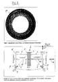
- the device 1 shown schematically in top view for testing the surface 1, namely the side wall, of a mounted on a rim, pressurized tire 2 comprises a projector 3 for projecting a stripe pattern on the surface 1 of the tire 2 and a A camera 4 comprising a pick-up optics and a CCD sensor for taking a picture of the stripe pattern projected onto the surface 1 of the tire 2.
- the tire 2 can be rotated by another device (not shown in the drawing) about its axis 5, namely its axis of rotation.
- the axis 5 extends in the horizontal direction.
- the plane spanned by the projection beam 6 and the receiving beam 7 also extends horizontally.
- the axis 5 is a part of this level.
- the projector 3 and the camera 4 are mounted at the ends of a housing fixed rail 8, which is perpendicular to the axis 5 in a horizontal plane.
- the projection beam 7 of the camera 4 is perpendicular to the surface 1 of the tire 2.
- the projection beam 6 strikes the surface 1 of the tire 2 at an angle of about 30 to 45 ° (other angles are also possible)
- Projector 3 projects a striped pattern only onto a partial surface of the sidewall of the tire 2.
- the camera 4 produces images of this part.
- the device further comprises an image processing device (not shown in the drawing), which is realized in particular by a corresponding program in a PC or other computer.
- the image processing device compares two shots of the camera 4 produced in different rotational positions of the tire 2, in particular by forming a differential image from two shots produced in different rotational positions of the tire 2. This process is then repeated for a plurality of preferably successive rotational positions of the tire 2.
- the projector 3 is further equipped with a flash light source (not shown in the drawing) which is synchronized with the camera 4 and the rotation angle of the tire 2 about the axis 5.
- a flash light source (not shown in the drawing) which is synchronized with the camera 4 and the rotation angle of the tire 2 about the axis 5.
- recordings can be made in a very short time, for example, in a 1/1000 second or even shorter times.
- the recordings can be made at standstill of the tire 2.
- the tire 2 should rotate "slowly" in proportion to the shutter speed of the camera 4 and / or the duration of a flash of the flash light source.
- the rotational speed of the tire 2 about the axis 5 should therefore be sufficiently low in relation to the exposure time of the camera 4 and / or the duration of a flash of the flash light source to obtain evaluable recordings.
- the device for testing the surface 1 of the tire 2 consists, as shown in Fig. 1, of a strip projection system mounted in a pressure test rig consisting of fringe projector 3 and camera 4 with connected image processing, wherein the triangulation plane of the fringe projection system expediently, as shown, radially to the tire 2 is arranged.
- the arrangement is aligned with a sector of the tire sidewall. However, it can also be aligned to the entire tire sidewall.
- the error is detected in such a way that two shots of the surface 1 of the tire 2 are made, the tire 2 is rotated between the recordings by a small angle in its axis 5. With each of the two images, the relative shape of the surface 1 of the tire 2 in the observed image area is measured (with a suitable calibration of the camera 4, it is also possible to obtain absolute shape data). When the two images taken with slightly twisted tire 2 are compared, it is found that the global shape is the same in both images, since the tire 2 is rotationally symmetric, but that there are significant deviations in shape at fault locations.
- the pictorial difference of the two photographs produced thus represents the difference of the relative (or absolute) shape of the surface 1 of the tire 2 and corresponds approximately to the known from the shearography representation of the local shape change.
- FIG. 9 shows a section through the first shot.
- a first amplitude 10 is generated by a first defect
- a second amplitude 11 is generated by a second defect.
- the middle line 12 shows a section through the second receptacle, in the production of which the tire 2 has been slightly rotated about its axis 5. Accordingly, the amplitudes 10 ', 11' relative to the associated amplitudes 10, 11 are slightly shifted to the right.
- the lower line 13 shows the difference result, wherein the values of the middle line 12 have been subtracted from the values of the upper line 9.
- the excursions of the differential amplitudes 10 "and 11" are greater than the amplitudes of the amplitudes 10, 11 and 10 'and 11'.
- Fig. 3 shows a comparative image prepared in this way, namely a differential image, the sidewall of a tire.
- the fault 14 is clearly visible and unambiguously recognizable. It corresponds to a dent or dent.
- the differential image representation according to FIG. 3 can still be quantitatively evaluated by suitable image processing and / or stored as a test document.
- the sensitivity of the measuring method can be easily determined by changing the tire rotation angle between shots.
- FIG. 4 An exemplary embodiment is shown in FIG. 4.
- the arrangement is symmetrical to the tire 2.
- components namely the projector 3 and the camera 4
- yet another projector 3 'and another camera 4' on the other side of the tire. 2 present, through which the opposite surface 1 ', so the other side wall of the tire 2 is checked. Since the structure is symmetrical, it does not need to be described again in detail.
- the projectors 3, 3 'and the cameras 4, 4' are each adjustable.
- the adjustability of the projector 3 and the camera 4 will be described.
- the projector 3 'and the camera 4' are adjustable in a corresponding manner.
- the rail 8 is attached approximately at its center to a Zustellachse 15.
- the Zustellachse 15 By actuating the Zustellachse 15, the rail can be moved in the direction of the double arrow 16, ie in the direction of the axis 5. An adjustment in this direction is used to adapt the projector 3 and the camera 4 to different tire widths.
- the projector 3 and the camera 4 are moved along the feed axis 15 in the direction of the double arrow 16 until the surface 1 of the tire is focused.
- the rail 8 can be fed in the direction of the double arrow 17.
- the projector 3 fixedly mounted thereon and the camera 4 fixedly mounted thereon move by being fed in the direction of the double arrow 17, ie in a horizontal plane in a direction perpendicular to the axis 5, the position of the projector 3 and the Camera 4 are adapted to different tire diameter.
Applications Claiming Priority (1)
| Application Number | Priority Date | Filing Date | Title |
|---|---|---|---|
| DE102004050355A DE102004050355A1 (de) | 2004-10-15 | 2004-10-15 | Verfahren und Vorrichtung zum Prüfen der Oberfläche eines Reifens |
Publications (3)
| Publication Number | Publication Date |
|---|---|
| EP1647817A2 true EP1647817A2 (fr) | 2006-04-19 |
| EP1647817A3 EP1647817A3 (fr) | 2011-12-07 |
| EP1647817B1 EP1647817B1 (fr) | 2017-11-08 |
Family
ID=34978837
Family Applications (1)
| Application Number | Title | Priority Date | Filing Date |
|---|---|---|---|
| EP05019655.9A Active EP1647817B1 (fr) | 2004-10-15 | 2005-09-09 | Méthode et dispositif pour test optique de surface de roue |
Country Status (3)
| Country | Link |
|---|---|
| US (1) | US7260983B2 (fr) |
| EP (1) | EP1647817B1 (fr) |
| DE (1) | DE102004050355A1 (fr) |
Cited By (2)
| Publication number | Priority date | Publication date | Assignee | Title |
|---|---|---|---|---|
| WO2009077534A1 (fr) * | 2007-12-19 | 2009-06-25 | Societe De Technologie Michelin | Dispositif d'evaluation de la surface d'un pneumatique |
| KR20180071285A (ko) * | 2015-10-09 | 2018-06-27 | 휠라이트 리미티드 | 타이어 상태 분석 |
Families Citing this family (17)
| Publication number | Priority date | Publication date | Assignee | Title |
|---|---|---|---|---|
| DE102006015123B4 (de) * | 2006-03-31 | 2008-03-20 | Mähner, Bernward | Vorrichtung und Verfahren zum Prüfen eines Reifens, insbesondere mittels eines interferometrischen Messverfahrens |
| JP4512578B2 (ja) * | 2006-10-27 | 2010-07-28 | 株式会社ブリヂストン | 分離フィルタ決定装置及びタイヤ検査装置 |
| US7677077B2 (en) * | 2006-12-21 | 2010-03-16 | The Goodyear Tire & Rubber Company | Sensor calibration device and method for a tire |
| JP5025442B2 (ja) * | 2007-12-10 | 2012-09-12 | 株式会社ブリヂストン | タイヤ形状検査方法とその装置 |
| US7805987B1 (en) * | 2008-08-19 | 2010-10-05 | Smith Bradley R | System and method for pneumatic tire defect detection |
| JP5318657B2 (ja) * | 2009-05-13 | 2013-10-16 | 株式会社ブリヂストン | タイヤの検査装置 |
| MX352132B (es) * | 2012-11-15 | 2017-11-08 | Android Ind Llc | Sistema y método para determinar la uniformidad de un neumático.. |
| JP6040770B2 (ja) * | 2012-12-28 | 2016-12-07 | 横浜ゴム株式会社 | タイヤ解析システムおよび解析方法 |
| WO2014117870A1 (fr) * | 2013-02-04 | 2014-08-07 | Me-Inspection Sk | Procédé, agencement de mesure et système servant à inspecter un objet tridimensionnel |
| WO2015058201A1 (fr) * | 2013-10-20 | 2015-04-23 | Starrett Bytewise Development, Inc. | Numériseur pour pneu |
| JP5964803B2 (ja) * | 2013-12-03 | 2016-08-03 | 株式会社神戸製鋼所 | データ処理方法及びデータ処理装置 |
| JP6318804B2 (ja) * | 2014-04-17 | 2018-05-09 | 横浜ゴム株式会社 | タイヤ解析装置およびタイヤ解析方法 |
| US10697857B2 (en) | 2014-12-22 | 2020-06-30 | Pirelli Tyre S.P.A. | Method and apparatus for checking tyres in a production line |
| WO2016103110A1 (fr) * | 2014-12-22 | 2016-06-30 | Pirelli Tyre S.P.A. | Appareil pour contrôler des pneus dans une chaîne de production |
| JP6457894B2 (ja) * | 2015-06-24 | 2019-01-23 | 住友ゴム工業株式会社 | トレッド形状測定方法及びトレッド形状測定装置 |
| WO2017001969A1 (fr) * | 2015-06-30 | 2017-01-05 | Pirelli Tyre S.P.A. | Procédé et appareil d'analyse d'une surface d'un pneu |
| US10962419B2 (en) | 2019-04-09 | 2021-03-30 | Carl Zeiss Optotechnik GmbH | Method for testing a tire by interferometry |
Citations (2)
| Publication number | Priority date | Publication date | Assignee | Title |
|---|---|---|---|---|
| EP1148328A2 (fr) | 2000-04-19 | 2001-10-24 | Mähner, Bernward | Procédé et dispositif d'essai optique de pneus |
| US20030160193A1 (en) | 2002-02-25 | 2003-08-28 | Patentes Talgo, S.A. | Rolling and lathing parameter measuring device by artificial viewing for railway vehicle wheels |
Family Cites Families (10)
| Publication number | Priority date | Publication date | Assignee | Title |
|---|---|---|---|---|
| DE19608632B4 (de) * | 1996-03-06 | 2005-12-29 | Scaps Gmbh | Vorrichtung zur Bestimmung der Topographie einer Oberfläche und Verfahren zu Bestimmen der Topographie einer Oberfläche |
| US6438272B1 (en) * | 1997-12-31 | 2002-08-20 | The Research Foundation Of State University Of Ny | Method and apparatus for three dimensional surface contouring using a digital video projection system |
| SE511985C2 (sv) * | 1999-01-28 | 2000-01-10 | Skogsind Tekn Foskningsinst | Topografisk bestämning av en av infallande ljus belyst yta |
| US6791695B2 (en) * | 1999-06-16 | 2004-09-14 | Bandag Licensing Corporation | Shearographic imaging machine with archive memory for animation data and air handling system |
| US6219143B1 (en) * | 1999-06-16 | 2001-04-17 | Bandag, Incorporated | Method and apparatus for analyzing shearogram images by animation |
| DE19930688A1 (de) * | 1999-07-02 | 2001-01-04 | Byk Gardner Gmbh | Vorrichtung und Verfahren zur Bestimmung der Qualität von Oberflächen |
| US6841017B2 (en) * | 2000-09-14 | 2005-01-11 | Bridgestone Corporation | Re-treading method and apparatus |
| KR100406843B1 (ko) * | 2001-04-06 | 2003-11-21 | (주) 인텍플러스 | 색정보를 이용한 실시간 3차원 표면형상 측정방법 및 장치 |
| US7355687B2 (en) * | 2003-02-20 | 2008-04-08 | Hunter Engineering Company | Method and apparatus for vehicle service system with imaging components |
| DE10313191A1 (de) * | 2003-03-25 | 2004-10-07 | Gutehoffnungshütte Radsatz Gmbh | Verfahren zur berührungslosen dynamischen Erfassung des Profils eines Festkörpers |
-
2004
- 2004-10-15 DE DE102004050355A patent/DE102004050355A1/de not_active Ceased
-
2005
- 2005-09-02 US US11/219,279 patent/US7260983B2/en not_active Expired - Fee Related
- 2005-09-09 EP EP05019655.9A patent/EP1647817B1/fr active Active
Patent Citations (2)
| Publication number | Priority date | Publication date | Assignee | Title |
|---|---|---|---|---|
| EP1148328A2 (fr) | 2000-04-19 | 2001-10-24 | Mähner, Bernward | Procédé et dispositif d'essai optique de pneus |
| US20030160193A1 (en) | 2002-02-25 | 2003-08-28 | Patentes Talgo, S.A. | Rolling and lathing parameter measuring device by artificial viewing for railway vehicle wheels |
Cited By (8)
| Publication number | Priority date | Publication date | Assignee | Title |
|---|---|---|---|---|
| WO2009077534A1 (fr) * | 2007-12-19 | 2009-06-25 | Societe De Technologie Michelin | Dispositif d'evaluation de la surface d'un pneumatique |
| FR2925706A1 (fr) * | 2007-12-19 | 2009-06-26 | Michelin Soc Tech | Dispositif d'evaluation de la surface d'un pneumatique. |
| CN101896865B (zh) * | 2007-12-19 | 2011-12-14 | 米其林技术公司 | 用于评价轮胎表面的设备 |
| US8659653B2 (en) | 2007-12-19 | 2014-02-25 | Michelin Recherche Et Technique S.A. | Device for evaluating the surface of a tire |
| KR20180071285A (ko) * | 2015-10-09 | 2018-06-27 | 휠라이트 리미티드 | 타이어 상태 분석 |
| CN108369088A (zh) * | 2015-10-09 | 2018-08-03 | 维奥赖特有限公司 | 轮胎状况分析 |
| EP3489623A1 (fr) * | 2015-10-09 | 2019-05-29 | Wheelright Limited | Méthode et system pour imager une paroi latérale d'un pneumatique |
| US10605697B2 (en) | 2015-10-09 | 2020-03-31 | Wheelright Limited | Tyre condition analysis |
Also Published As
| Publication number | Publication date |
|---|---|
| US20060083347A1 (en) | 2006-04-20 |
| EP1647817A3 (fr) | 2011-12-07 |
| EP1647817B1 (fr) | 2017-11-08 |
| US7260983B2 (en) | 2007-08-28 |
| DE102004050355A1 (de) | 2006-04-27 |
Similar Documents
| Publication | Publication Date | Title |
|---|---|---|
| EP1647817B1 (fr) | Méthode et dispositif pour test optique de surface de roue | |
| EP2851670B1 (fr) | Appareil de vérification de pneu, installation de vérification de pneu et procédé de vérification de pneu | |
| DE19849793C1 (de) | Vorrichtung und Verfahren zur berührungslosen Erfassung von Unebenheiten in einer gewölbten Oberfläche | |
| DE102018110749B3 (de) | Verfahren zum Überprüfen eines Druckzylinders und eine entsprechende Anordnung | |
| EP1959227A2 (fr) | Dispositif et procédé destinés à la vérification d'un pneu, en particulier à l'aide d'un procédé de mesure interférométrique | |
| DE102006015123B4 (de) | Vorrichtung und Verfahren zum Prüfen eines Reifens, insbesondere mittels eines interferometrischen Messverfahrens | |
| DE102008015499B4 (de) | Verfahren und Vorrichtung zur Bestimmung der 3D-Koordinaten eines Objekts | |
| DE10333802B4 (de) | Verfahren und Vorrichtung zum Prüfen von Reifen | |
| EP2732236A1 (fr) | Dispositif et procédé optiques de contrôle de pneumatiques | |
| DE10019386A1 (de) | Verfahren und Vorrichtung zur Prüfung von Reifen | |
| EP3199943B1 (fr) | Dispositif et procédé de détection d'au moins une surface en partie réfléchissante | |
| DE2602001B2 (de) | Vorrichtung zur Überprüfung einer bearbeiteten Oberfläche eines Werkstücks | |
| DE102004007828A1 (de) | Verfahren und System zur Inspektion von Oberflächen | |
| DE3937559A1 (de) | Verfahren zum ermitteln von optischen fehlern in scheiben aus einem transparenten material, insbesondere aus glas | |
| EP3545259A1 (fr) | Procédé et dispositif d'analyse d'objets de test à symétrie de révolution | |
| EP1581803B1 (fr) | Procede et dispositif de detection de defauts de surface sur des pieces ou des composants presentant des surfaces brillantes | |
| DE102005032244A1 (de) | Vorrichtung und Verfahren zur Fehlerdetektierung an einer Kante | |
| DE102017129737A1 (de) | Vorrichtung zur berührungslosen, optischen 3D-Erfassung einer Stirnfläche eines sich queraxial bewegenden, stabförmigen Artikels der tabakverarbeitenden Industrie | |
| WO2018068775A1 (fr) | Procédé et système de détermination de la surface d'au moins un défaut sur au moins une surface fonctionnelle d'un composant ou d'un corps de test | |
| EP3328649A1 (fr) | Procédé de vérification d'une unité fonctionnelle destinée à être utilisée contre une feuille conintue en défilement | |
| DE10019387C2 (de) | Verfahren und Vorrichtung zur Untersuchung von Reifen | |
| DE3600199A1 (de) | Verfahren zum ermitteln optischer fehler in scheiben aus transparentem material | |
| DE10009870C2 (de) | Verfahren und Vorrichtung zur Untersuchung von Prüfobjekten | |
| DE102019121662A1 (de) | Verfahren zur Prüfung eines Reifens | |
| EP2799847B1 (fr) | Procédé de contrôle optique de surfaces d'objets |
Legal Events
| Date | Code | Title | Description |
|---|---|---|---|
| PUAI | Public reference made under article 153(3) epc to a published international application that has entered the european phase |
Free format text: ORIGINAL CODE: 0009012 |
|
| AK | Designated contracting states |
Kind code of ref document: A2 Designated state(s): AT BE BG CH CY CZ DE DK EE ES FI FR GB GR HU IE IS IT LI LT LU LV MC NL PL PT RO SE SI SK TR |
|
| AX | Request for extension of the european patent |
Extension state: AL BA HR MK YU |
|
| PUAL | Search report despatched |
Free format text: ORIGINAL CODE: 0009013 |
|
| AK | Designated contracting states |
Kind code of ref document: A3 Designated state(s): AT BE BG CH CY CZ DE DK EE ES FI FR GB GR HU IE IS IT LI LT LU LV MC NL PL PT RO SE SI SK TR |
|
| AX | Request for extension of the european patent |
Extension state: AL BA HR MK YU |
|
| RIC1 | Information provided on ipc code assigned before grant |
Ipc: G01M 17/02 20060101AFI20111101BHEP Ipc: G01B 11/30 20060101ALI20111101BHEP Ipc: G01B 11/25 20060101ALI20111101BHEP |
|
| 17P | Request for examination filed |
Effective date: 20120531 |
|
| AKX | Designation fees paid |
Designated state(s): DE FR GB IT |
|
| 17Q | First examination report despatched |
Effective date: 20120725 |
|
| GRAP | Despatch of communication of intention to grant a patent |
Free format text: ORIGINAL CODE: EPIDOSNIGR1 |
|
| INTG | Intention to grant announced |
Effective date: 20170421 |
|
| GRAS | Grant fee paid |
Free format text: ORIGINAL CODE: EPIDOSNIGR3 |
|
| RAP1 | Party data changed (applicant data changed or rights of an application transferred) |
Owner name: CARL ZEISS OPTOTECHNIK GMBH |
|
| GRAA | (expected) grant |
Free format text: ORIGINAL CODE: 0009210 |
|
| AK | Designated contracting states |
Kind code of ref document: B1 Designated state(s): DE FR GB IT |
|
| REG | Reference to a national code |
Ref country code: GB Ref legal event code: FG4D Free format text: NOT ENGLISH |
|
| REG | Reference to a national code |
Ref country code: DE Ref legal event code: R096 Ref document number: 502005015738 Country of ref document: DE |
|
| REG | Reference to a national code |
Ref country code: DE Ref legal event code: R097 Ref document number: 502005015738 Country of ref document: DE |
|
| PLBE | No opposition filed within time limit |
Free format text: ORIGINAL CODE: 0009261 |
|
| STAA | Information on the status of an ep patent application or granted ep patent |
Free format text: STATUS: NO OPPOSITION FILED WITHIN TIME LIMIT |
|
| REG | Reference to a national code |
Ref country code: FR Ref legal event code: PLFP Year of fee payment: 14 |
|
| 26N | No opposition filed |
Effective date: 20180809 |
|
| PGFP | Annual fee paid to national office [announced via postgrant information from national office to epo] |
Ref country code: FR Payment date: 20230216 Year of fee payment: 18 |
|
| PGFP | Annual fee paid to national office [announced via postgrant information from national office to epo] |
Ref country code: IT Payment date: 20230223 Year of fee payment: 18 Ref country code: GB Payment date: 20230220 Year of fee payment: 18 Ref country code: DE Payment date: 20230216 Year of fee payment: 18 |