EP1647772B1 - Combustor - Google Patents
Combustor Download PDFInfo
- Publication number
- EP1647772B1 EP1647772B1 EP05021839A EP05021839A EP1647772B1 EP 1647772 B1 EP1647772 B1 EP 1647772B1 EP 05021839 A EP05021839 A EP 05021839A EP 05021839 A EP05021839 A EP 05021839A EP 1647772 B1 EP1647772 B1 EP 1647772B1
- Authority
- EP
- European Patent Office
- Prior art keywords
- fuel
- mixing chamber
- mixing
- combustion
- air inlet
- Prior art date
- Legal status (The legal status is an assumption and is not a legal conclusion. Google has not performed a legal analysis and makes no representation as to the accuracy of the status listed.)
- Expired - Lifetime
Links
Images


Classifications
-
- F—MECHANICAL ENGINEERING; LIGHTING; HEATING; WEAPONS; BLASTING
- F23—COMBUSTION APPARATUS; COMBUSTION PROCESSES
- F23R—GENERATING COMBUSTION PRODUCTS OF HIGH PRESSURE OR HIGH VELOCITY, e.g. GAS-TURBINE COMBUSTION CHAMBERS
- F23R3/00—Continuous combustion chambers using liquid or gaseous fuel
- F23R3/28—Continuous combustion chambers using liquid or gaseous fuel characterised by the fuel supply
- F23R3/286—Continuous combustion chambers using liquid or gaseous fuel characterised by the fuel supply having fuel-air premixing devices
-
- F—MECHANICAL ENGINEERING; LIGHTING; HEATING; WEAPONS; BLASTING
- F23—COMBUSTION APPARATUS; COMBUSTION PROCESSES
- F23C—METHODS OR APPARATUS FOR COMBUSTION USING FLUID FUEL OR SOLID FUEL SUSPENDED IN A CARRIER GAS OR AIR
- F23C7/00—Combustion apparatus characterised by arrangements for air supply
- F23C7/002—Combustion apparatus characterised by arrangements for air supply the air being submitted to a rotary or spinning motion
- F23C7/004—Combustion apparatus characterised by arrangements for air supply the air being submitted to a rotary or spinning motion using vanes
-
- F—MECHANICAL ENGINEERING; LIGHTING; HEATING; WEAPONS; BLASTING
- F23—COMBUSTION APPARATUS; COMBUSTION PROCESSES
- F23R—GENERATING COMBUSTION PRODUCTS OF HIGH PRESSURE OR HIGH VELOCITY, e.g. GAS-TURBINE COMBUSTION CHAMBERS
- F23R3/00—Continuous combustion chambers using liquid or gaseous fuel
- F23R3/28—Continuous combustion chambers using liquid or gaseous fuel characterised by the fuel supply
- F23R3/34—Feeding into different combustion zones
- F23R3/343—Pilot flames, i.e. fuel nozzles or injectors using only a very small proportion of the total fuel to insure continuous combustion
-
- F—MECHANICAL ENGINEERING; LIGHTING; HEATING; WEAPONS; BLASTING
- F23—COMBUSTION APPARATUS; COMBUSTION PROCESSES
- F23C—METHODS OR APPARATUS FOR COMBUSTION USING FLUID FUEL OR SOLID FUEL SUSPENDED IN A CARRIER GAS OR AIR
- F23C2900/00—Special features of, or arrangements for combustion apparatus using fluid fuels or solid fuels suspended in air; Combustion processes therefor
- F23C2900/07001—Air swirling vanes incorporating fuel injectors
-
- F—MECHANICAL ENGINEERING; LIGHTING; HEATING; WEAPONS; BLASTING
- F23—COMBUSTION APPARATUS; COMBUSTION PROCESSES
- F23R—GENERATING COMBUSTION PRODUCTS OF HIGH PRESSURE OR HIGH VELOCITY, e.g. GAS-TURBINE COMBUSTION CHAMBERS
- F23R2900/00—Special features of, or arrangements for continuous combustion chambers; Combustion processes therefor
- F23R2900/03343—Pilot burners operating in premixed mode
Definitions
- the present invention relates to a combustor.
- Patent Documents disclose a double conical burner provided with a fuel supply member on an outer surface of a swirler
- WO 2005/121648A relates to a premix burner provided with a stepped liquid fuel supply system.
- Said burner comprises at least two partially conical shells that are radially arranged in a partially overlapping manner and define an axially conically extending turbulence chamber, the central axes of said shells extending in a staggered manner and the mutually overlapping shell regions thereof respectively enclosing an air inlet vent extending tangentially in relation to the turbulence chamber.
- the inventive burner also comprises a lance which axially protrudes into the turbulence chamber and is provided with means for feeding liquid fuel into the turbulence chamber, and other means which are used to feed liquid fuel and are provided in the region of the air inlet vents.
- the invention is characterized in that the other means for feeding liquid fuel are embodied and arranged along at least one air inlet vent, in such a way that the liquid fuel delivery conditioned by the other means is carried out in the form of a fuel spray diffusing perpendicularly to the tangential longitudinal extension of the air inlet vent, and perpendicularly to an air flow directed through the air inlet vent.
- a combustor which comprises a mixing-chamber forming member for forming therein a mixing chamber in which air for combustion and fuel are mixed with each other; and a combustion chamber for burning a gas mixture mixed in the mixing chamber and producing combustion gases, wherein at least one channel for supplying the air for combustion to the mixing chamber from the outer peripheral side of the mixing-chamber forming member is provided inside the mixing-chamber forming member.
- the mixing-chamber forming member has an outer periphery formed into a substantially cylindrical shape.
- a plurality of channels for supplying the air for combustion to said mixing chamber from the outer peripheral side of said mixing-chamber forming member are provided inside said mixing-chamber forming member at intervals in the axial direction.
- a combustor which can suppress backfire and ensure stable combustion.
- a combustor includes a mixing-chamber forming member for forming therein a mixing chamber in which air for combustion and fuel are mixed with each other, and a channel for supplying the air for combustion to the mixing chamber from the outer peripheral side of the mixing-chamber forming member is provided inside the mixing-chamber forming member.
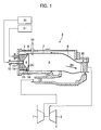
- Fig. 1 shows an overall construction of a gas turbine plant according to the first embodiment of the present invention.
- Fig. 1 shows, as a side sectional view, a structure of a gas turbine combustor in the plant.
- the gas turbine plant primarily comprises a compressor 1 for compressing air and producing high-pressure air for combustion, a combustor 2 for mixing the compressed air introduced from the compressor 1 and fuel with each other and producing combustion gases with burning of a gas mixture, and a gas turbine 3 to which are introduced the combustion gases produced by the combustor 2.
- the compressor 1 and the gas turbine 3 are mechanically coupled to each other.
- the combustor 2 comprises a burner 11 including a mixing chamber 4 in which the fuel is mixed to the air for combustion and a mixing chamber wall 5 which serves as a mixing-chamber forming member to form the mixing chamber 4 therein, a combustion chamber 6 for burning the gas mixture mixed in the mixing chamber 4 and producing the combustion gases, an inner casing 7 for forming the combustion chamber 6 therein, a transition piece 8 for introducing the combustion gases from the inner casing 7 to the gas turbine 3, an outer casing 9 housing the burner 11, the inner casing 7 and the transition piece 8 therein, and an ignition plug 10 supported by the outer casing 9 and igniting the gas mixture in the combustion chamber 6.
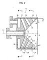
- Fig. 2 is a side sectional view showing a detailed structure of the burner 11.
- an inner wall surface 5a of the mixing-chamber forming member for forming the mixing chamber 4 therein has a diffuser-like shape or a hollow conical shape gradually spreading toward the combustion chamber 6 (to the right as viewed in Fig. 2 , namely in the ejecting direction of a first fuel nozzle 13 described below).
- the first fuel nozzle 13 for ejecting first fuel to a position upstream of the combustion chamber 6 is disposed nearly an apex of the conical-shaped mixing-chamber inner wall surface 5a such that the first fuel nozzle 13 is substantially coaxial with an axis L1 of the mixing chamber wall 5.
- the mixing chamber 4 has an outer wall surface 5b in a cylindrical shape.
- Air inlet holes 14, 15 and 16 for introducing the air for combustion from the compressor 1 are bored in the mixing chamber wall 5 in plural stages (three stages in this embodiment) in the direction of the axis L1 (hereinafter referred to as the "axial direction") and in plural points in the circumferential direction per stage such that those air inlet holes 14, 15 and 16 are arranged successively in this order from the upstream side in the axial direction (i.e., from the left side as viewed in Fig. 2 ).
- channels defined by the air inlet holes 14, 15 and 16, etc. are formed inside the mixing-chamber forming member.
- Fuel holes 17, 18 and 19 are formed to be communicated with the air inlet holes 14, 15 and 16, respectively, for ejecting second fuel through respective wall surfaces forming the air inlet holes 14, 15 and 16. More specifically, the fuel holes 17, 18 and 19 are bored to be opened at respective inner wall surfaces of the air inlet holes 14, 15 and 16 near the mixing-chamber outer wall surface 5b, and also opened to a fuel manifold 12 for the second fuel, which is provided upstream of the mixing chamber 4.
- the second fuel can be ejected in a direction substantially perpendicular to respective axes L2, L3 and L4 of the air inlet holes 14, 15 and 16. Thus, the second fuel is supplied substantially at a right angle relative to the airflow.
- the first fuel is supplied to the first fuel nozzle 13 through a first fuel supply line 20, and the second fuel is supplied to the fuel holes 17, 18 and 19 through a second fuel supply line 21 (see Fig. 1 ).
- the first fuel and the second fuel may be the same kind of gaseous fuel or liquid fuel. For example, they may be gaseous fuels differing in heating value. Alternatively, the first fuel and the second fuel may be respectively liquid fuel and gaseous fuel.
- the air inlet holes 14, 15 and 16 are formed such that angles at which the air for combustion is introduced to the mixing chamber 4 through the respective air inlet holes 14, 15 and 16 are changed gradually at least relative to the circumferential direction of the mixing chamber wall 5. More specifically, in the upstream side of the mixing chamber 4, the plurality of air inlet holes 14 are each arranged so as to eject a jet flow of the air for combustion or a jet flow of a mixture of the gaseous liquid and the air for combustion toward a point near the position where the liquid fuel is ejected from the first fuel nozzle 13.
- the air inlet holes 15 and 16 are arranged so as to eject jet flows of the air for combustion or jet flows of a mixture of the gaseous liquid and the air for combustion to advance closer to an inner circumferential surface of the mixing chamber wall 5, i.e., the mixing-chamber inner wall surface 5a. That arrangement will be described in more detail below with reference to Figs. 3 and 4 , as well as Fig. 2 .
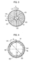
- Fig. 3 is a side sectional view (taken along the line III-III in Fig. 2 ) of the mixing chamber wall 5 at an axial position where the air inlet holes 14 are bored.
- Fig. 4 is a side sectional view (taken along the line IV-IV in Fig. 2 ) of the mixing chamber wall 5 at an axial position where the air inlet holes 16 are bored.
- X represents the offset distance between the axis L2, L4 of the air inlet hole 14, 16 and the axis L1 of the mixing chamber wall 5 (i.e., the length of a segment connecting the axis L1 and the axis L2, L4 in perpendicular relation), and D represents the inner diameter of the mixing chamber wall 5 at each axial position where the air inlet hole 14, 16 is bored.
- the angles of the air inlet holes 14, 15 and 16 relative to the circumferential direction are changed such that X/D increases as a position approaches the downstream side in the axial direction of the mixing chamber wall 5 (to the right as viewed in Fig. 2 ).
- X/D takes a smaller value at the upstream position in the mixing chamber 4. Therefore, the air for combustion ejected from each air inlet hole 14 flows in toward the vicinity of the axis L1 of the mixing chamber wall 5 (i.e., the vicinity of the position where the liquid fuel is ejected from the first fuel nozzle 13), as indicated by an arrow (C) in Fig. 3 .
- X/D takes a larger value at the downstream position in the mixing chamber 4. Therefore, the air for combustion ejected from each air inlet hole 16 flows in more closely to the inner circumferential surface of the mixing chamber wall 5, i.e., the mixing-chamber inner wall surface 5a, as indicated by an arrow (D) in Fig. 4 .
- angles at which the air inlet holes 14, 15 and 16 are formed to extend are also gradually changed with respect to the axis L1. More specifically, as shown in Fig. 2 , each air inlet hole 14 located in the most upstream side of the mixing chamber wall 5 has a relatively large angle ⁇ 1 (e.g., such an angle as causing a plane including the axis L2 of the air inlet hole 14 to intersect the axis L1 substantially at a right angle) between its axis L2 and the inner circumferential surface of the mixing chamber wall 5, i.e., the mixing-chamber inner wall surface 5a.
- ⁇ 1 e.g., such an angle as causing a plane including the axis L2 of the air inlet hole 14 to intersect the axis L1 substantially at a right angle
- the air inlet holes 15, 16 located in the intermediate and downstream sides of the mixing chamber wall 5 have a relatively small angle ⁇ 2 (e.g., about 90°) between their axes L3, L4 and the inner circumferential surface of the mixing chamber wall 5, i.e., the mixing-chamber inner wall surface 5a.
- ⁇ 2 e.g., about 90°
- the air for combustion ejected from the air inlet hole 14 flows into the mixing chamber 4 substantially at a right angle relative to the axis L1 (i.e., to the liquid fuel ejected from the first fuel nozzle 13).
- the air inlet holes 15, 16 have relatively large X/D values as described above, the holes are opened to orient more closely to the circumferential direction, and the air inlet holes 15, 16 have larger-size outlet openings (in the side facing the mixing chamber 4). Therefore, if the air inlet holes 15, 16 are formed to have the same angle ⁇ 1 relative to the mixing-chamber inner wall surface 5a as that of the air inlet hole 14, outlet openings of adjacent holes interfere with each other. This means that the number of the bored air inlet holes 15, 16 in the circumferential direction has to be reduced.
- the angle between the axis L3, L4 of the air inlet hole 15, 16 and the mixing-chamber inner wall surface 5a is set to ⁇ 2, i.e., a substantially right angle. Therefore, the size of each outlet opening of the air inlet hole 15, 16 can be reduced so as to ensure the necessary number of the bored air inlet holes 15, 16 in the circumferential direction. With that structure, the mixing chamber 4 and the mixing chamber wall 5 can be made more compact.
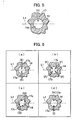
- Fig. 5 is a sectional view (taken along the line V-V in Fig. 2 ) of the mixing chamber wall 5 in a portion including the fuel hole 17 bored to be communicated with the air inlet hole 14.
- the fuel hole 17 is bored in one-to-one relation to the air inlet hole 14 at a right angle relative to the axis L1 so that the gaseous fuel is supplied toward the center of the air inlet hole 14, as indicated by an arrow (E) in Fig. 5 .
- the air inlet holes 14, 15 and 16 are each of a structure having a length enough to premix the gaseous fuel introduced through the gaseous fuel holes 17, 18 and 19 and the air for combustion with each other and are narrowed in diameter in the downstream side or have bent portions, there is a risk of causing spontaneous ignition of the gas mixture in the air inlet holes 14, 15 and 16 or backfire, i.e., backward run of flames, into the air inlet holes 14, 15 and 16 from the combustion chamber 6 through the mixing chamber 4, and then holding the flames by vortexes generated in low flow-rate regions upstream of the narrowed portions or in the bent portions.
- the mixing chamber wall 5 may be susceptible to deformations or damages due to overheating, and therefore a failure of the overall gas turbine plant has to be taken into consideration.
- the air inlet holes 14, 15 and 16 for introducing the air for combustion and the gaseous fuel ejected from the gaseous fuel holes 17, 18 and 19 to the mixing chamber 4 while mixing them are each of the structural component neither having shapes narrowed in diameter in the downstream side, nor including bent portions at which vortexes are possibly generated. Therefore, even if flames enter the air inlet holes 14, 15 and 16 due to spontaneous ignition, backward run of the flames, or mixing of the burnable dust or the like into the air for combustion, the flames are avoided from residing in the air inlet holes 14, 15 and 16, and are immediately expelled out into the mixing chamber 4. As a result, the trouble of flames running backward and being held in the air inlet holes 14, 15 and 16 can be prevented.
- the fuel holes 17, 18 and 19 are bored to be opened at the respective inner wall surfaces of the air inlet holes 14, 15 and 16, there are no structural components around the air inlet holes 14, 15 and 16, which may disturb the airflow or generate vortexes. Therefore, the airflow entering the mixing chamber is less susceptible to combustion oscillations, etc. and a flame can be avoided from running backward. As a result, this embodiment is able to suppress the occurrence of backfire.
- the fuel ejection speed is increased and more efficient diffusion is realized when the ejected fuel strikes against the wall surface 14a, thus resulting in further promotion of the mixing of the gaseous fuel with the airflow.
- this embodiment has the structure capable of ejecting the gaseous fuel from the fuel hole 17 (18 or 19) in a direction substantially perpendicular to the airflow in the air inlet hole 14 (15 or 16) and setting the diameter of the air inlet hole 14 (15 or 16) to a relatively small value in comparison with penetration power (distance) of the gaseous fuel, the speed of the ejected fuel at the time of striking against the wall surface 14a is less attenuated and the gaseous fuel is more efficiently diffused to further promote the mixing of the gaseous fuel with the airflow.
- the air for combustion and the gaseous fuel both introduced to the air inlet holes 14, 15 and 16 are sufficiently mixed with each other in the air inlet holes 14, 15 and 16 (a mixture of the air for combustion and the gaseous fuel in this state is referred to as a "primary gas mixture” hereinafter).
- the primary gas mixture is ejected into the mixing chamber 4 from the air inlet holes 14, 15 and 16, and the mixing of the air for combustion and the gaseous fuel is promoted by eddy flows generated upon the ejection of the primary gas mixture (a mixture of the air for combustion and the gaseous fuel in this state is referred to as a "secondary gas mixture” hereinafter).
- Those eddy flows are ones usually generated when a channel size is increased in a stepwise manner.
- the angles of the air inlet holes 14, 15 and 16 relative to the circumferential direction are changed such that X/D increases as a position approaches the downstream side in the axial direction of the mixing chamber wall 5.
- the secondary gas mixture ejected from each air inlet hole 14 flows in toward the vicinity of the position where the liquid fuel is ejected from the first fuel nozzle 13. Accordingly, the secondary gas mixtures ejected from the plurality of air inlet holes 14 collide with one another at high speeds, whereby the mixing is further promoted.
- the secondary gas mixtures ejected from the air inlet holes 15, 16 flow in more closely to the inner circumferential surface of the mixing chamber wall 5, i.e., the mixing-chamber inner wall surface 5a. Accordingly, strong swirl flows are generated in the mixing chamber 4, causing the secondary gas mixtures ejected from the plurality of air inlet holes 15 and the plurality of air inlet holes 16 to collide with one another, whereby the mixing is further greatly promoted. In such a way, the secondary gas mixtures ejected from the air inlet holes 14, 15 and 16 are sufficiently mixed in the mixing chamber 4.
- the air inlet hole located in the more upstream side is formed to have a larger length, primary mixing of the gaseous fuel and the air for combustion is further promoted in the air inlet hole located in the more upstream side.
- the liquid fuel ejected from the first fuel nozzle 13 for the liquid fuel is atomized with shearing forces given by the air for combustion that is ejected from the air inlet holes 14 and collides with the flow of the liquid fuel substantially at a right angle. Further, a part of the ejected liquid fuel is evaporated into gases. Accordingly, mixing of the ejected liquid fuel with the air for combustion ejected from the air inlet holes 15, 16 is promoted while the liquid fuel is forced to flow toward the downstream side of the mixing chamber 4 (a mixture of the liquid fuel, the gaseous fuel and the air for combustion in such a state is referred to as a "premixed gas mixture" hereinafter).
- the mixing chamber 4 being of the single structure, sufficient mixing can be achieved between the gaseous fuel and the air for combustion and between the liquid fuel and the air for combustion so as to produce a homogeneous premixed gas mixture. Consequently, it is possible to reduce the amount of generated NOx regardless of which kind of fuel is used.
- liquid droplets having relatively large sizes may strike against the mixing-chamber inner wall surface 5a while overcoming the swirl forces of the swirl flows due to their own inertial forces.
- the air inlet holes 14, 15 and 16 are formed over the entire region along the mixing-chamber inner wall surface 5a in the circumferential direction thereof, the air for combustion ejected from the air inlet holes 14, 15 and 16 acts to blow off the liquid droplets that are going to strike against the mixing-chamber inner wall surface 5a. As a result, the occurrence of coking can be prevented with higher reliability.
- the droplets of the liquid fuel ejected from the first fuel nozzle 13 are forced to flow outward of the axis L1 by centrifugal forces.
- the air for combustion flows in from the entire region in the circumferential direction, as described above, toward the vicinity of the position where the liquid fuel is ejected from the first fuel nozzle 13 for supplying the liquid fuel, the ejected liquid droplets can be suppressed from spreading outward and can be prevented from striking against the mixing-chamber inner wall surface 5a.
- the action of shearing forces of the air for combustion upon the liquid fuel is maximized, it is possible to more efficiently atomize the liquid droplets and to greatly promote the mixing of the air for combustion and the liquid fuel.
- angles of the air inlet holes 14, 15 and 16 relative to the circumferential direction are changed such that X/D increases as a position approaches the downstream side in the axial direction of the mixing chamber wall 5.
- X/D takes a larger value at a position closer to the downstream side in the axial direction of the mixing chamber wall 5, and the premixed gas mixture flows into a combustion region while generating strong swirl flows in an outlet area of the mixing chamber 4.
- a recirculation region is formed near the axis of the mixing chamber 4, and combustion stability can be further improved.
- FIG. 6 is a side sectional view showing the air inlet hole 14 and a part of the fuel hole 17 in the second embodiment.
- the fuel holes 17, 18 and 19 are formed so as to eject the gaseous fuel into the interiors of the corresponding air inlet holes in a direction substantially perpendicular to the airflow, the gaseous fuel ejected from each fuel hole strikes against the wall surface of the air inlet hole 14 and is diffused, which is positioned opposite to the fuel hole. Accordingly, the primary mixing of the gaseous fuel with the airflow in the air inlet hole is greatly promoted.
- each fuel hole is formed, as in the first embodiment, such that the gaseous fuel is ejected in a direction substantially perpendicular to the airflow.
- the fuel ejection speeds from the fuel holes 17a, 17b are increased and more efficient diffusion is realized when the flows of the I ejected fuel collide with each other, thus resulting in further promotion of the mixing.
- Fig. 6(c) shows still another example in which two fuel holes 17c are formed to be opened to one air inlet hole 14.
- the fuel holes 17c are disposed nearly tangential to the inner wall surface of the air inlet hole such that flows of the gaseous fuel are ejected to advance along the inner wall surface of the air inlet hole and to swirl in the air inlet hole 14, as indicated by arrows (G) in the drawing. Since the gaseous fuel ejected from the fuel holes 17c flows downward while swirling in the air inlet hole 14 as indicated by the arrows (G), a contact time of the gaseous fuel with the air for combustion is prolonged and the mixing of the gaseous fuel with the air is greatly promoted.
- this example shows the case forming two fuel holes for one air inlet hole, the effect of promoting the mixing is also expected when only one fuel hole 17c is formed.
- the primary mixing is promoted with the effect of increasing the contact area or the contact time of the gaseous fuel with the airflow.
- the secondary mixing in the mixing chamber 4 is also promoted, whereby the amount of NOx generated can be further reduced.
- Fig. 6(d) shows an example in which two fuel holes 17d, 17e having cross-sectional areas different from each other are formed to be opened to one air inlet hole 14.
- the fuel hole 17d ejects main gaseous fuel
- the fuel hole 17e ejects sub-gaseous fuel differing in heating value from the main gaseous fuel.
- the main gaseous fuel is ejected from the fuel hole 17d as indicated by an arrow (I) in the drawing, and the byproduct fuel is ejected from the fuel hole 17e as indicated by an arrow (H). Accordingly, the air, the main fuel, and the byproduct fuel are mixed with one another in the air inlet hole, whereby mixing of them is promoted.
- the cross-sectional area of the fuel hole 17e is adjusted depending on the flow rate of the byproduct fuel.
- the gaseous fuel supplied to the fuel hole 17e is not limited to combustible gaseous fuel, and it may be nitrogen, steam or the like.
- a gas turbine combustor according to a third embodiment of the present invention will be described below with reference to Fig. 7 .
- the axial length of the mixing chamber wall is extended and the air inlet holes are arranged to be concentrated in the upstream side of the mixing chamber wall.
- a mixing chamber wall 105 is formed to have a spreading angle smaller than and an axial length larger than those of the mixing chamber wall 5 in the first embodiment. Then, air inlet holes 114, 115, 116, 117 and 118 are bored in layout concentrated in the upstream side of the mixing chamber wall 105.
- the air inlet holes 114, 115, 116, 117 and 118 are formed at angles gradually changed relative to the circumferential direction such that X/D increases as a position approaches the downstream side of the mixing chamber wall 105 in the axial direction thereof, i.e., such that the air inlet hole 114 has a smaller X/D value and the air inlet hole 118 has a larger X/D value.
- angles at which the air inlet holes 114, 115, 116, 117 and 118 are formed relative to an axis L5 of the mixing chamber wall 105 are not changed depending on the hole positions along the axis L5. Namely, all planes including respective axes (not shown) of the air inlet holes 114, 115, 116, 117 and 118 intersect the axis L5 substantially at a right angle.
- Gaseous fuel holes 119, 120, 121 and 122 for ejecting gaseous fuel are formed to be opened in plural-to-one relation to the air inlet holes 115, 116, 117 and 118, respectively, such that one or more pairs of the gaseous fuel holes are positioned opposite to each other with corresponding one of the air inlet holes 114, 115, 116, 117 and 118 interposed therebetween, as shown in Fig. 6(a) .
- the gaseous fuel can be ejected from the gaseous fuel holes 119, 120, 121 and 122 in a direction substantially perpendicular to respective axes (not shown) of the air inlet holes 115, 116, 117 and 118.
- the spreading angle of an inner circumferential surface (chamber inner wall surface) 105a of the mixing chamber wall 105 relative to the axis L5 is set to a relatively small angle ⁇ 3 in the upstream and intermediate sides of a mixing chamber 104 and to a relatively large angle ⁇ 4 in the downstream side thereof.
- the spreading angle is increased in an outlet region of the mixing chamber 104.
- the third embodiment thus constituted can provide not only the above-described effects of preventing backfire, reducing the amount of NOx generated, preventing coking, and improving combustion stability which are obtained with the first and second embodiments, but also the following effects.
- combustion stability can be further improved with the third embodiment as described in above (7), the combustion stability can be maintained at a level comparable to that in the first embodiment even when the swirl forces of the premixed gas mixture in the outlet region of the mixing chamber are weakened.
- combustion stability can be maintained by setting X/D of the air inlet holes 114, 115, 116, 117 and 118 to small values so that the swirl flows in the outlet region of the mixing chamber are weakened and the formation of the recirculation region is lessened to suppress backward run of flames.
- the flame can be suppressed from running backward to the interior of the mixing chamber 104 from the combustion region while maintaining the combustion stability. It is hence possible to more reliably prevent backfire.
- the liquid fuel ejected from the liquid fuel nozzle 113 evaporates in a larger rate corresponding to an increase of the mixing distance. Simultaneously, the mixing of the liquid fuel and the air for combustion can also be further promoted and a more homogeneous premixed gas mixture can be produced. It is hence possible to further reduce the amount of NOx generated.
- the so-called flicker i.e., a phenomenon that a fire is turned on and off, may occur if a fuel concentration is reduced at the start of fuel supply or due to a failure of a fuel supply line.
- the occurrence of the flicker fluctuates pressure within the combustor, and the pressure fluctuations cause the flame to run backward into the mixing chamber 104, whereby the interior of the mixing chamber 104 and the liquid fuel nozzle 113 are overheated in some cases.
- the liquid fuel nozzle 113 is cooled by the air for combustion ejected from the air inlet hole 114. As a result, in spite of the occurrence of the flicker, the liquid fuel nozzle 113 can be prevented from being overheated.
- the mixing chamber wall 105 having a hollow conical shape and a small reflectance is disposed in the inlet portion of the combustor 2 serving as the other reflecting end, the pressure wave is damped by the mixing chamber wall 105 when it impinges upon the mixing chamber wall 105, whereby the generation of the combustion oscillations can be suppressed. Note that this effect of suppressing the generation of the combustion oscillations can also be obtained in the first and second embodiments as well.
- a gas turbine combustor according to a fourth embodiment of the present invention will be described below with reference to Fig. 8 .
- the spreading angle of in the outlet region of the mixing chamber is set to a smaller value than that in the third embodiment.
- Fig. 8 is a side sectional view showing a detailed burner structure in the fourth embodiment. Similar parts in Fig. 8 to those in Fig. 7 showing the third embodiment are denoted by the same symbols and a description of such parts is omitted here.
- a burner 111' in this fourth embodiment is formed such that the outlet region of the mixing chamber 104 has a spreading angle ⁇ 5 smaller than ⁇ 3 of the mixing chamber 104.
- the cross-sectional area of the mixing chamber 104 in the outlet region thereof is reduced to increase the outlet speed of the premixed gas mixture as compared with the third embodiment.
- the fourth embodiment thus constituted can provide not only the above-described effects of preventing backfire, reducing the amount of NOx generated, preventing coking, improving combustion stability, suppressing overheating of the liquid fuel nozzle, and suppressing generation of combustion oscillations which are obtained with the third embodiment, but also the following effects.
- a gas turbine combustor according to a fifth embodiment of the present invention will be described below with reference to Figs. 9 through 11 .
- the inner wall of the mixing chamber is formed in a hollow cylindrical shape, and the cross-sectional area of the air inlet hole in the upstream side in the axial direction is set to be larger than those of the air inlet holes in the downstream side.
- a mixing chamber wall 205 is formed to have an inner circumferential surface (mixing-chamber inner wall surface) 205a in cylindrical shape of the same diameter in the axial direction.
- An air inlet hole 214 formed in the most upstream side of the mixing chamber wall 205 has an inner diameter larger than those of other air inlet holes 215, 216, 217 and 218.
- the air inlet holes 214, 215, 216, 217 and 218 are formed at angles gradually changed relative to the circumferential direction, as shown in Figs.
- Gas fuel holes 219, 220, 221 and 222 for ejecting gaseous fuel are formed to be opened in plural-to-one relation to the air inlet holes 215, 216, 217 and 218, respectively, such that one or more pairs of the gaseous fuel holes are positioned opposite to each other with corresponding one of the air inlet holes 215, 216, 217 and 218 interposed therebetween.
- the gaseous fuel can be ejected from the gaseous fuel holes 219, 220, 221 and 222 in a direction substantially perpendicular to respective axes (not shown) of the air inlet holes 215, 216, 217 and 218.
- the spreading angle of the inner circumferential surface 205a of the mixing chamber wall 205 relative to the axis L5 is set to a relatively large angle ⁇ 6 in the downstream side of the mixing chamber 204. In other words, the spreading angle is increased in an outlet region of the mixing chamber 204.
- the fifth embodiment thus constituted can provide not only effects similar to the above-described ones which are obtained with the third embodiment, but also the following effects.
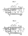
- a gas turbine combustor according to a sixth embodiment of the present invention will be described below with reference to Figs. 12 through 14 .
- a small mixing chamber having a hollow conical shape is formed inside a large mixing chamber having a hollow cylindrical shape, and the air inlet holes are formed to introduce the air for combustion to both of the mixing chambers.
- a second mixing chamber wall 305 is formed to have an inner circumferential surface (mixing-chamber inner wall surface) 305a in cylindrical shape, and air inlet holes 315, 316, 317 and 318 for introducing the air for combustion to a second mixing chamber 304 are formed in the second mixing chamber wall 305.
- a first mixing chamber 322 having a hollow conical shape and being smaller than the second mixing chamber 304 is formed at an upstream end of the second mixing chamber 304, and an air inlet hole 314 for introducing the air for combustion to a first mixing chamber 322 is formed in the second mixing chamber wall 305.
- a liquid fuel nozzle 313 is disposed at an upstream end of the first mixing chamber 322.
- the air inlet hole 314 for introducing the air for combustion to the first mixing chamber 322 is formed in plural such that swirl flows are produced to act clockwise looking from the downstream side of the burner 311, as indicated by arrows (J) in the drawing.
- the air inlet hole 315 (316, 317 or 318) communicating with the second mixing chamber 304 is formed in plural such that swirl flows are produced to act counterclockwise looking from the downstream side of the burner 311, as indicated by arrows (K) in the drawing.
- the air inlet holes 315 (316, 317 or 318) communicating with the second mixing chamber 304 are formed to cause stronger swirl actions.
- Gas fuel holes 319, 320 and 321 for ejecting gaseous fuel are formed to be opened in plural-to-one relation to the air inlet holes 316, 317 and 318, respectively, such that one or more pairs of the gaseous fuel holes are positioned opposite to each other with corresponding one of the air inlet holes 316, 317 and 318 interposed therebetween.
- the gaseous fuel can be ejected from the gaseous fuel holes 319, 320 and 321 in a direction substantially perpendicular to respective axes (not shown) of the air inlet holes 316, 317 and 318.
- the spreading angle of the inner circumferential surface 305a of the mixing chamber wall 305 relative to the axis L5 is set to a relatively large angle ⁇ 6 in the downstream side of the mixing chamber 304. In other words, the spreading angle is increased in an outlet region of the mixing chamber 304.
- the sixth embodiment thus constituted can provide not only effects similar to the above-described ones which are obtained with the fifth embodiment, but also the following effects.
- the liquid fuel ejected from the liquid fuel nozzle 313 is atomized with shearing forces given by the airflows entering from the air inlet holes 314 as in the first through fifth embodiments.
- the atomized liquid droplets are carried with the airflows ejected from the air inlet holes 314 and flow downstream into the second mixing chamber 304 while swirling clockwise. Because the air inlet holes 315, 316, 317 and 318 communicating with the second mixing chamber 304 are all formed to cause the counterclockwise swirl actions as shown in Fig. 14 , the airflows swirling in the opposed directions cross each other at an outlet of the first mixing chamber 322.
- first fuel nozzles 13, 113, 213 and 313 for the liquid fuel are not described in detail in the first through sixth embodiments of the present invention, those first fuel nozzles 13, 113, 213 and 313 may be each any spray type liquid fuel nozzle, such as a pressure-spray swirl type atomizer (with a single orifice or double orifices), a pressure-spray collision nozzle, or a spray air nozzle. Also, while any of the above-described embodiments has been described as having only one first fuel nozzle 13, 113, 213 or 313 for the liquid fuel, the present invention is not limited to such an arrangement and a plurality of liquid fuel nozzles may be disposed for one mixing chamber.
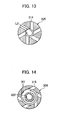
- a gas turbine combustor according to a seventh embodiment of the present invention will be described below with reference to Fig. 15 .
- the combustor is constituted in a combination of two types of burners by disposing the burner according to the first embodiment as a pilot burner at the center and the burner according to the third embodiment in plural as main burners around the pilot burner.
- Fig. 15 is a side sectional view showing, in enlarged scale, an inlet portion of the combustor according to the seventh embodiment. Similar parts in Fig. 15 to those in Figs. 2 and 7 showing respectively the first and third embodiments are denoted by the same symbols and a description of such parts is omitted here.
- the burner 11 according to the first embodiment is disposed as a pilot burner at the center of an inlet of the combustion chamber 6, and the burner 111 according to the third embodiment is disposed in plural as main burners around the pilot burner. Plates 31 are disposed between an outlet of the pilot burner 11 and outlets of the main burners 111 to assist holding of flames.
- a liquid fuel supply line 38 is connected to the first fuel nozzle 13 for liquid fuel and a gaseous fuel supply line 39 is connected to the gaseous fuel holes 17, 18 and 19.
- a liquid fuel supply line 40 is connected to the liquid fuel nozzle 113 and a gaseous fuel supply line 41 is connected to the gaseous fuel holes 119, 120, 121 and 122.
- the mixing chamber wall 5 is formed to have a larger spreading angle and a shorter mixing distance in the axial direction than those in the burner 111 according to the third embodiment. Also, the air inlet holes 14, 15 and 16 are bored in the mixing chamber wall 5 all over the upstream, intermediate and downstream sides. Therefore, even if a flame comes close to the mixing chamber 4, a temperature rise of the mixing chamber wall 5 can be suppressed.
- the ratio of a flow rate of fuel (liquid fuel, gaseous fuel, or a mixture of liquid and gaseous fuel) to a flow rate of the air for combustion can be set to a larger value, and the burner 11 can provide stable combustion in a combustion state closer to diffusive combustion than the burner 111. For that reason, in this embodiment, the burner 11 is employed as the pilot burner and is ignited in a startup and speedup stage of the gas turbine plant in which the fuel-air ratio and the flow rate of combustion gases are largely changed.
- the burner 111 according to the third embodiment has a narrower combustion stable range because of having a longer mixing distance in the axial direction and provides combustion characteristics closer to premixed combustion than the burner 11 according to the first embodiment.
- the burner 111 is employed as the main burner and is ignited in a low load stage (state after the startup and speedup stage) of the gas turbine plant in which change in the flow rate of the air for combustion is reduced. Then, a combustion rate of the burner 111 is increased after entering a constant load state. By operating the burners in such a manner, the amount of NOx generated can be reduced.
- the present invention has been described as using two types of burners differing in structure, i.e., the pilot burner and the main burner, the present invention is not limited to that embodiment, and burners having the same structure may be used.
- the burner 11 according to the first embodiment can be operated in states changing from the diffusive combustion state to the premixed combustion state just by controlling the fuel flow rate, the burner 11 may be used as each of the pilot burner and the main burner. This modification can also provide similar effects to those obtained with the seventh embodiment.
- any structural component disturbing the airflow or generating vortexes is not present near the upstream side of the air inlet holes in the seventh embodiment as well.
- a structural component such as a fuel supply member is present on an outer surface of a swirler as in the related art ( JP, A 2004-507701 )
- the structural component disturbs the airflow around the swirler, and small but relatively strong vortexes are generated downstream of the structural component, thus causing flames to be held in the air inlet holes by the generated vortexes.
- the vortexes generated by the fuel supply member for the adjacent swirler may flow into that swirler.
- the static pressure distribution at an inlet of particular one of the plural swirlers is changed, whereby the flow rate of air flowing into that one swirler becomes different from a design value. This may lead to a possibility that the distributions of fuel concentration within the swirlers are so disturbed as to generate combustion oscillations, and a flame is caused to run backward with an increase of the combustion oscillations.
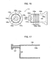
- a gas turbine combustor according to an eighth embodiment of the present invention will be described below with reference to Figs. 16 through 18 .
- This eighth embodiment concerns a burner manufacturing method.
- the following description is made of the burner manufacturing method, taking the burner 111, shown in Fig. 3 , according to the third embodiment as an example.
- Fig. 16 shows the mixing chamber 105 of the burner 111.
- the hollow conical wall surface 105a is formed so as to spread gradually in the direction of flow.
- four small grooves 119a, 120a, 121a and 122a each extending in the circumferential direction to provide a circular path are formed at intervals in the axial direction, and large grooves 130a, 131a, 132a, 133a, 134a and 135a extending in the axial direction of the mixing chamber 105 are formed perpendicularly to the small grooves 119a, 120a, 121a and 122a.
- a nozzle mount hole 105c in which the fuel nozzle 113 is to be inserted is formed in an upstream end wall of the mixing chamber 105, and the upstream end wall of the mixing chamber 105 is formed to have an outer circumferential wall surface 105d of a smaller diameter than the outer circumferential wall surface 105b in the downstream side of the mixing chamber 105.
- the large grooves 130a, 131a, 132a, 133a, 134a and 135a formed in the outer circumferential wall surface 105b of the mixing chamber 105 have a larger cross-sectional area than that of the small grooves 119a, 120a, 121a and 122a.
- Fig. 17 shows a cover 136 of the mixing chamber 105.
- the cover 136 is provided at its upstream end (leftward end as viewed in the drawing) with a fuel pipe 137 through which gaseous fuel is supplied to a fuel manifold 112 in the mixing chamber 105.
- An insertion hole 138 is formed in the cover 136 in match with the outer circumferential wall surface 105d of the mixing chamber 105 at the upstream end thereof.
- the cover 136 has an inner circumferential wall surface 136a formed in match with the outer circumferential wall surface 105b of the mixing chamber 105 in the downstream side thereof.
- Fig. 18 shows a state in which the cover 136, shown in Fig. 17 , is fitted over the mixing chamber 105, shown in Fig. 16 , from the upstream side of the mixing chamber 105.
- the cover 136 is fixed to the mixing chamber 105 by welding at joining points WA, WB.
- WA, WB welding at joining points WA, WB.
- the fuel manifold 112 is formed upstream of the mixing chamber 105, and the small grooves 119a, 120a, 121a and 122a formed in the outer circumferential wall surface 105b of the mixing chamber 105 are communicated with the fuel manifold 112 through the large grooves 130a, 131a, 132a, 133a, 134a and 135a.
- the air inlet holes 114, 115, 116, 117 and 118 are formed so as to locate not only at circumferential intermediate points between adjacent two of the large grooves 130a, 131a, 132a, 133a, 134a and 135a formed in the outer circumferential wall surface 105b of the mixing chamber 105, but also on respective axes of the small grooves 119a, 120a, 121a and 122a.
- flows of fuel are caused to collide with each other and to diffuse in the air inlet hole, as shown in Fig. 6(a) , while the cross-sectional area of the small groove is controlled to regulate the ejection speed of the fuel from each of the fuel holes 119b, 119c.
- a contact area of the fuel with the air for combustion is increased and the mixing of the fuel and the air can be promoted.
- a combustor comprises a mixing-chamber forming member for forming therein a mixing chamber in which air for combustion and fuel are mixed with each other; and a combustion chamber for burning a gas mixture generated by the mixing chamber and producing combustion gases, wherein a channel for supplying the air for combustion to the mixing chamber from the outer peripheral side of the mixing-chamber forming member is provided inside the mixing-chamber forming member.
- a structural component such as a channel is mounted to supply the air for combustion to an outer surface of a swirler as in the related art ( JP,A 2004-507701 )
- small but relatively strong vortexes are generated downstream of the structural component, thus causing flames to be held in the air inlet holes by the generated vortexes.
- the vortexes generated by the structural component flow into the swirler without decay, whereby flames are held and backfire is generated.
- the channel for supplying the air for combustion to the mixing chamber is provided inside the mixing-chamber forming member. This feature eliminates the necessity of providing the channel on the outer side of the mixing-chamber forming member.
- any structural component disturbing the airflow or generating vortexes is not provided on the surface of the swirler, the occurrence of backfire can be suppressed.
- any structural component such as a channel for supplying the air for combustion, is not present on the outer side of the mixing-chamber forming member, i.e., in an inlet area for the air inlet holes, disturbances of the airflow and generation of the vortexes caused by the presence of that structural component can be suppressed. It is hence possible to supply the air at a stable flow rate into the mixing chamber and to improve combustion stability.
- a combustor comprises a mixing-chamber forming member for forming therein a mixing chamber in which air for combustion and fuel are mixed with each other; and a combustion chamber for burning a gas mixture mixed in the mixing chamber and producing combustion gases, wherein the mixing-chamber forming member has an outer periphery formed into a substantially cylindrical shape, a channel for supplying the air for combustion to the mixing chamber from the outer peripheral side of the mixing-chamber forming member is provided inside the mixing-chamber forming member, and the channel is provided in a wall surface thereof with a fuel supply portion such that the air for combustion and the fuel are supplied to the mixing chamber through the channel.
- the air for combustion can be suppressed from being disturbed by an outer peripheral surface of the mixing-chamber forming member. It is therefore possible to supply the air at a more stable flow rate into the mixing chamber and to further improve combustion stability.
- the air for combustion can be stably supplied to the plurality of burners.
- the fuel supply portion in the wall surface of the channel such that the air for combustion and the fuel are supplied to the mixing chamber through the channel, the air for combustion and the fuel can be mixed with each other before being supplied to the mixing chamber.
- a combustor comprises a fuel nozzle for supplying fuel; a mixing chamber for mixing the fuel and air therein; a combustion chamber for burning a gas mixture mixed in the mixing chamber; and a mixing-chamber forming member including the mixing chamber formed therein, wherein the mixing-chamber forming member has an outer periphery formed into a substantially cylindrical shape, a plurality of channels for supplying the air for combustion to the mixing chamber from the outer peripheral side of the mixing-chamber forming member are provided inside the mixing-chamber forming member at intervals in the axial direction, and the channel is provided in a wall surface thereof with a fuel supply portion for supplying the fuel to the channel.
- a combustor comprises a fuel nozzle for supplying fuel; a mixing chamber disposed around and downstream of the fuel nozzle and mixing the fuel and air therein; a combustion chamber disposed downstream of the mixing chamber and burning a gas mixture mixed in the mixing chamber; and a mixing-chamber forming member including the mixing chamber formed therein, wherein the mixing-chamber forming member has an outer periphery formed into a substantially cylindrical shape, a plurality of channels for supplying the air for combustion to the mixing chamber from the outer peripheral side of the mixing-chamber forming member are provided inside the mixing-chamber forming member at intervals in the axial direction, and the channel is provided in a wall surface thereof with a fuel supply portion such that the fuel and the air are premixed in the channel and a premixed gas mixture is supplied to the mixing chamber.
- the premixed gas mixture (primary gas mixture) produced with premixing of the fuel and the air in the channel
- the fuel and the air can be premixed in the channel for supplying the air for combustion before being supplied to the mixing chamber, and the mixing in the mixing chamber can be further promoted. Consequently, unbalance of fuel concentration in the air is eliminated in the premixed gas mixture discharged from the mixing chamber, thus resulting in a premixed gas mixture with the fuel homogeneously mixed therein.
- the fuel hole is formed to be directly opened to the wall surface of the air inlet hole in the burner, there is no need of separately providing a fuel channel on the outer side of the burner so that the burner has a compact outer surface.
- the burner has a cylindrical outer shape and includes no structural component disturbing a stream of the air for combustion which flows around the burner, the air for combustion can be suppressed from peeling away from the outer surface of the burner and from generating separation vortexes. As a result, it is possible to suppress backfire that is caused when the separation vortexes are introduced to the air inlet holes.
- the air for combustion flows more smoothly along the outer surface of the burner than the case where the burner outer surface has any structural component in irregular shape including recesses or projections. Accordingly, it is possible to reduce a pressure loss that is caused upon supply of the air for combustion to the burner, and to increase overall efficiency of a gas turbine.
- the mixing chamber is formed into a diffuser-like shape gradually spreading from the upstream side toward the downstream side, the flow speed can be suppressed from being decelerated in the upstream side of the mixing chamber. As a result, the occurrence of backfire can be suppressed.
- the present invention is able to provide the combustor which can suppress backfire and ensure stable combustion.
Landscapes
- Engineering & Computer Science (AREA)
- Chemical & Material Sciences (AREA)
- Combustion & Propulsion (AREA)
- Mechanical Engineering (AREA)
- General Engineering & Computer Science (AREA)
Priority Applications (1)
| Application Number | Priority Date | Filing Date | Title |
|---|---|---|---|
| EP10185167.3A EP2282114B1 (en) | 2004-10-06 | 2005-10-06 | Combustor and combustion method for combustor |
Applications Claiming Priority (1)
| Application Number | Priority Date | Filing Date | Title |
|---|---|---|---|
| JP2004293182A JP4626251B2 (ja) | 2004-10-06 | 2004-10-06 | 燃焼器及び燃焼器の燃焼方法 |
Related Child Applications (2)
| Application Number | Title | Priority Date | Filing Date |
|---|---|---|---|
| EP10185167.3A Division EP2282114B1 (en) | 2004-10-06 | 2005-10-06 | Combustor and combustion method for combustor |
| EP10185167.3 Division-Into | 2010-10-01 |
Publications (2)
| Publication Number | Publication Date |
|---|---|
| EP1647772A1 EP1647772A1 (en) | 2006-04-19 |
| EP1647772B1 true EP1647772B1 (en) | 2010-12-29 |
Family
ID=35453364
Family Applications (2)
| Application Number | Title | Priority Date | Filing Date |
|---|---|---|---|
| EP05021839A Expired - Lifetime EP1647772B1 (en) | 2004-10-06 | 2005-10-06 | Combustor |
| EP10185167.3A Expired - Lifetime EP2282114B1 (en) | 2004-10-06 | 2005-10-06 | Combustor and combustion method for combustor |
Family Applications After (1)
| Application Number | Title | Priority Date | Filing Date |
|---|---|---|---|
| EP10185167.3A Expired - Lifetime EP2282114B1 (en) | 2004-10-06 | 2005-10-06 | Combustor and combustion method for combustor |
Country Status (4)
| Country | Link |
|---|---|
| US (2) | US7610759B2 (enExample) |
| EP (2) | EP1647772B1 (enExample) |
| JP (1) | JP4626251B2 (enExample) |
| DE (1) | DE602005025576D1 (enExample) |
Families Citing this family (123)
| Publication number | Priority date | Publication date | Assignee | Title |
|---|---|---|---|---|
| TWI273642B (en) * | 2002-04-19 | 2007-02-11 | Ulvac Inc | Film-forming apparatus and film-forming method |
| HUE059355T2 (hu) * | 2002-10-10 | 2022-11-28 | Lpp Comb Llc | Eljárás folyékony tüzelõanyagok elpárologtatására égetés céljára |
| US7831933B2 (en) | 2004-03-17 | 2010-11-09 | Leapfrog Enterprises, Inc. | Method and system for implementing a user interface for a device employing written graphical elements |
| JP4920597B2 (ja) | 2004-12-08 | 2012-04-18 | エル・ピー・ピー コンバスション エル・エル・シー | 液体炭化水素燃料を調整する方法および装置 |
| CA2599113C (en) * | 2005-02-25 | 2011-11-22 | Ihi Corporation | Fuel injection valve, combustor using the fuel injection valve, and fuel injection method for the fuel injection valve |
| JP5023526B2 (ja) * | 2006-03-23 | 2012-09-12 | 株式会社Ihi | 燃焼器用バーナ及び燃焼方法 |
| US8529646B2 (en) * | 2006-05-01 | 2013-09-10 | Lpp Combustion Llc | Integrated system and method for production and vaporization of liquid hydrocarbon fuels for combustion |
| JP4977522B2 (ja) * | 2007-04-25 | 2012-07-18 | 株式会社日立製作所 | ガスタービン燃焼器 |
| EP1985926B1 (en) * | 2007-04-26 | 2018-09-05 | Mitsubishi Hitachi Power Systems, Ltd. | Combustion equipment and combustion method |
| MY156350A (en) | 2008-03-28 | 2016-02-15 | Exxonmobil Upstream Res Co | Low emission power generation and hydrocarbon recovery systems and methods |
| MY153097A (en) | 2008-03-28 | 2014-12-31 | Exxonmobil Upstream Res Co | Low emission power generation and hydrocarbon recovery systems and methods |
| US8065881B2 (en) * | 2008-08-12 | 2011-11-29 | Siemens Energy, Inc. | Transition with a linear flow path with exhaust mouths for use in a gas turbine engine |
| US8091365B2 (en) * | 2008-08-12 | 2012-01-10 | Siemens Energy, Inc. | Canted outlet for transition in a gas turbine engine |
| US8113003B2 (en) * | 2008-08-12 | 2012-02-14 | Siemens Energy, Inc. | Transition with a linear flow path for use in a gas turbine engine |
| EP2169312A1 (en) * | 2008-09-25 | 2010-03-31 | Siemens Aktiengesellschaft | Stepped swirler for dynamic control |
| BRPI0920139A2 (pt) | 2008-10-14 | 2015-12-22 | Exxonmobil Upstream Res Co | sistema de combustão, método de controle de combustão, e, sistema de combustor. |
| US8454350B2 (en) * | 2008-10-29 | 2013-06-04 | General Electric Company | Diluent shroud for combustor |
| US8616007B2 (en) * | 2009-01-22 | 2013-12-31 | Siemens Energy, Inc. | Structural attachment system for transition duct outlet |
| US9140454B2 (en) * | 2009-01-23 | 2015-09-22 | General Electric Company | Bundled multi-tube nozzle for a turbomachine |
| US8205452B2 (en) * | 2009-02-02 | 2012-06-26 | General Electric Company | Apparatus for fuel injection in a turbine engine |
| US8539773B2 (en) * | 2009-02-04 | 2013-09-24 | General Electric Company | Premixed direct injection nozzle for highly reactive fuels |
| CA2764450C (en) | 2009-06-05 | 2018-02-13 | Exxonmobil Upstream Research Company | Combustor systems and methods for using same |
| CN102597418A (zh) | 2009-11-12 | 2012-07-18 | 埃克森美孚上游研究公司 | 低排放发电和烃采收系统及方法 |
| JP5448762B2 (ja) | 2009-12-02 | 2014-03-19 | 三菱重工業株式会社 | ガスタービン用燃焼バーナ |
| KR101814096B1 (ko) * | 2010-02-23 | 2018-01-02 | 아사히 유키자이 가부시키가이샤 | 인라인형 유체 혼합 장치 |
| US9038373B2 (en) | 2010-05-03 | 2015-05-26 | Cummins Inc. | Ammonia sensor control of an SCR aftertreatment system |
| US8640448B2 (en) | 2010-05-03 | 2014-02-04 | Cummins Inc. | Transient compensation control of an SCR aftertreatment system |
| US9476338B2 (en) | 2010-05-03 | 2016-10-25 | Cummins Inc. | Ammonia sensor control, with NOx feedback, of an SCR aftertreatment system |
| TWI593878B (zh) | 2010-07-02 | 2017-08-01 | 艾克頌美孚上游研究公司 | 用於控制燃料燃燒之系統及方法 |
| MY160832A (en) | 2010-07-02 | 2017-03-31 | Exxonmobil Upstream Res Co | Stoichiometric combustion with exhaust gas recirculation and direct contact cooler |
| AU2011271636B2 (en) | 2010-07-02 | 2016-03-17 | Exxonmobil Upstream Research Company | Low emission power generation systems and methods |
| EA029301B1 (ru) | 2010-07-02 | 2018-03-30 | Эксонмобил Апстрим Рисерч Компани | Интегрированные системы для получения со(варианты) и способ производства электроэнергии |
| CA2801494C (en) | 2010-07-02 | 2018-04-17 | Exxonmobil Upstream Research Company | Stoichiometric combustion of enriched air with exhaust gas recirculation |
| CN105736150B (zh) | 2010-08-06 | 2018-03-06 | 埃克森美孚上游研究公司 | 优化化学计量燃烧的系统和方法 |
| WO2012018458A1 (en) * | 2010-08-06 | 2012-02-09 | Exxonmobil Upstream Research Company | System and method for exhaust gas extraction |
| JP5156066B2 (ja) * | 2010-08-27 | 2013-03-06 | 株式会社日立製作所 | ガスタービン燃焼器 |
| US20120067054A1 (en) * | 2010-09-21 | 2012-03-22 | Palmer Labs, Llc | High efficiency power production methods, assemblies, and systems |
| RU2560099C2 (ru) * | 2011-01-31 | 2015-08-20 | Дженерал Электрик Компани | Топливное сопло (варианты) |
| TWI564474B (zh) | 2011-03-22 | 2017-01-01 | 艾克頌美孚上游研究公司 | 於渦輪系統中控制化學計量燃燒的整合系統和使用彼之產生動力的方法 |
| TWI563165B (en) | 2011-03-22 | 2016-12-21 | Exxonmobil Upstream Res Co | Power generation system and method for generating power |
| TWI593872B (zh) | 2011-03-22 | 2017-08-01 | 艾克頌美孚上游研究公司 | 整合系統及產生動力之方法 |
| TWI563166B (en) | 2011-03-22 | 2016-12-21 | Exxonmobil Upstream Res Co | Integrated generation systems and methods for generating power |
| JP5380488B2 (ja) | 2011-05-20 | 2014-01-08 | 株式会社日立製作所 | 燃焼器 |
| JP5507504B2 (ja) * | 2011-07-19 | 2014-05-28 | 株式会社日立製作所 | ガスタービン燃焼器 |
| JP5393745B2 (ja) * | 2011-09-05 | 2014-01-22 | 川崎重工業株式会社 | ガスタービン燃焼器 |
| US20130122436A1 (en) * | 2011-11-11 | 2013-05-16 | General Electric Company | Combustor and method for supplying fuel to a combustor |
| CN104428490B (zh) | 2011-12-20 | 2018-06-05 | 埃克森美孚上游研究公司 | 提高的煤层甲烷生产 |
| US9134031B2 (en) * | 2012-01-04 | 2015-09-15 | General Electric Company | Combustor of a turbomachine including multiple tubular radial pathways arranged at multiple circumferential and axial locations |
| US9353682B2 (en) | 2012-04-12 | 2016-05-31 | General Electric Company | Methods, systems and apparatus relating to combustion turbine power plants with exhaust gas recirculation |
| US10273880B2 (en) | 2012-04-26 | 2019-04-30 | General Electric Company | System and method of recirculating exhaust gas for use in a plurality of flow paths in a gas turbine engine |
| US9784185B2 (en) | 2012-04-26 | 2017-10-10 | General Electric Company | System and method for cooling a gas turbine with an exhaust gas provided by the gas turbine |
| US9366432B2 (en) | 2012-05-17 | 2016-06-14 | Capstone Turbine Corporation | Multistaged lean prevaporizing premixing fuel injector |
| US9267690B2 (en) | 2012-05-29 | 2016-02-23 | General Electric Company | Turbomachine combustor nozzle including a monolithic nozzle component and method of forming the same |
| JP5988261B2 (ja) * | 2012-06-07 | 2016-09-07 | 川崎重工業株式会社 | 燃料噴射装置 |
| US10100741B2 (en) | 2012-11-02 | 2018-10-16 | General Electric Company | System and method for diffusion combustion with oxidant-diluent mixing in a stoichiometric exhaust gas recirculation gas turbine system |
| US9631815B2 (en) | 2012-12-28 | 2017-04-25 | General Electric Company | System and method for a turbine combustor |
| US9574496B2 (en) | 2012-12-28 | 2017-02-21 | General Electric Company | System and method for a turbine combustor |
| US10107495B2 (en) | 2012-11-02 | 2018-10-23 | General Electric Company | Gas turbine combustor control system for stoichiometric combustion in the presence of a diluent |
| US9803865B2 (en) | 2012-12-28 | 2017-10-31 | General Electric Company | System and method for a turbine combustor |
| US9869279B2 (en) * | 2012-11-02 | 2018-01-16 | General Electric Company | System and method for a multi-wall turbine combustor |
| US9599070B2 (en) | 2012-11-02 | 2017-03-21 | General Electric Company | System and method for oxidant compression in a stoichiometric exhaust gas recirculation gas turbine system |
| US9611756B2 (en) | 2012-11-02 | 2017-04-04 | General Electric Company | System and method for protecting components in a gas turbine engine with exhaust gas recirculation |
| US9708977B2 (en) | 2012-12-28 | 2017-07-18 | General Electric Company | System and method for reheat in gas turbine with exhaust gas recirculation |
| US10215412B2 (en) | 2012-11-02 | 2019-02-26 | General Electric Company | System and method for load control with diffusion combustion in a stoichiometric exhaust gas recirculation gas turbine system |
| US10208677B2 (en) | 2012-12-31 | 2019-02-19 | General Electric Company | Gas turbine load control system |
| US9581081B2 (en) | 2013-01-13 | 2017-02-28 | General Electric Company | System and method for protecting components in a gas turbine engine with exhaust gas recirculation |
| US9512759B2 (en) | 2013-02-06 | 2016-12-06 | General Electric Company | System and method for catalyst heat utilization for gas turbine with exhaust gas recirculation |
| US9938861B2 (en) | 2013-02-21 | 2018-04-10 | Exxonmobil Upstream Research Company | Fuel combusting method |
| TW201502356A (zh) | 2013-02-21 | 2015-01-16 | Exxonmobil Upstream Res Co | 氣渦輪機排氣中氧之減少 |
| RU2637609C2 (ru) | 2013-02-28 | 2017-12-05 | Эксонмобил Апстрим Рисерч Компани | Система и способ для камеры сгорания турбины |
| TW201500635A (zh) | 2013-03-08 | 2015-01-01 | Exxonmobil Upstream Res Co | 處理廢氣以供用於提高油回收 |
| US9618261B2 (en) | 2013-03-08 | 2017-04-11 | Exxonmobil Upstream Research Company | Power generation and LNG production |
| WO2014137648A1 (en) | 2013-03-08 | 2014-09-12 | Exxonmobil Upstream Research Company | Power generation and methane recovery from methane hydrates |
| US20140250945A1 (en) | 2013-03-08 | 2014-09-11 | Richard A. Huntington | Carbon Dioxide Recovery |
| TWI654368B (zh) | 2013-06-28 | 2019-03-21 | 美商艾克頌美孚上游研究公司 | 用於控制在廢氣再循環氣渦輪機系統中的廢氣流之系統、方法與媒體 |
| US9617914B2 (en) | 2013-06-28 | 2017-04-11 | General Electric Company | Systems and methods for monitoring gas turbine systems having exhaust gas recirculation |
| US9835089B2 (en) | 2013-06-28 | 2017-12-05 | General Electric Company | System and method for a fuel nozzle |
| US9631542B2 (en) | 2013-06-28 | 2017-04-25 | General Electric Company | System and method for exhausting combustion gases from gas turbine engines |
| US9587510B2 (en) | 2013-07-30 | 2017-03-07 | General Electric Company | System and method for a gas turbine engine sensor |
| US9903588B2 (en) | 2013-07-30 | 2018-02-27 | General Electric Company | System and method for barrier in passage of combustor of gas turbine engine with exhaust gas recirculation |
| US9951658B2 (en) | 2013-07-31 | 2018-04-24 | General Electric Company | System and method for an oxidant heating system |
| JP6210810B2 (ja) | 2013-09-20 | 2017-10-11 | 三菱日立パワーシステムズ株式会社 | デュアル燃料焚きガスタービン燃焼器 |
| US10030588B2 (en) | 2013-12-04 | 2018-07-24 | General Electric Company | Gas turbine combustor diagnostic system and method |
| US9752458B2 (en) | 2013-12-04 | 2017-09-05 | General Electric Company | System and method for a gas turbine engine |
| US10227920B2 (en) | 2014-01-15 | 2019-03-12 | General Electric Company | Gas turbine oxidant separation system |
| US9915200B2 (en) | 2014-01-21 | 2018-03-13 | General Electric Company | System and method for controlling the combustion process in a gas turbine operating with exhaust gas recirculation |
| US9863267B2 (en) | 2014-01-21 | 2018-01-09 | General Electric Company | System and method of control for a gas turbine engine |
| US10079564B2 (en) | 2014-01-27 | 2018-09-18 | General Electric Company | System and method for a stoichiometric exhaust gas recirculation gas turbine system |
| US9593853B2 (en) * | 2014-02-20 | 2017-03-14 | Siemens Energy, Inc. | Gas flow path for a gas turbine engine |
| US10001042B2 (en) | 2014-03-03 | 2018-06-19 | Cummins Inc. | Systems, methods, and apparatus for reductant dosing in an SCR aftertreatment system |
| EP2930430A1 (en) * | 2014-04-07 | 2015-10-14 | Siemens Aktiengesellschaft | A burner tip and a burner for a gas turbine |
| US20150285502A1 (en) * | 2014-04-08 | 2015-10-08 | General Electric Company | Fuel nozzle shroud and method of manufacturing the shroud |
| US10047633B2 (en) | 2014-05-16 | 2018-08-14 | General Electric Company | Bearing housing |
| EP3161267A1 (en) | 2014-06-26 | 2017-05-03 | Siemens Energy, Inc. | Converging flow joint insert system at an intersection between adjacent transitions duct bodies |
| JP2017524118A (ja) | 2014-06-26 | 2017-08-24 | シーメンス エナジー インコーポレイテッド | 隣接する移行ダクト体の間の交差部における収束流れ接合部挿入システム |
| US9885290B2 (en) | 2014-06-30 | 2018-02-06 | General Electric Company | Erosion suppression system and method in an exhaust gas recirculation gas turbine system |
| US10060359B2 (en) | 2014-06-30 | 2018-08-28 | General Electric Company | Method and system for combustion control for gas turbine system with exhaust gas recirculation |
| US10655542B2 (en) | 2014-06-30 | 2020-05-19 | General Electric Company | Method and system for startup of gas turbine system drive trains with exhaust gas recirculation |
| JP6325930B2 (ja) * | 2014-07-24 | 2018-05-16 | 三菱日立パワーシステムズ株式会社 | ガスタービン燃焼器 |
| US9869247B2 (en) | 2014-12-31 | 2018-01-16 | General Electric Company | Systems and methods of estimating a combustion equivalence ratio in a gas turbine with exhaust gas recirculation |
| US9819292B2 (en) | 2014-12-31 | 2017-11-14 | General Electric Company | Systems and methods to respond to grid overfrequency events for a stoichiometric exhaust recirculation gas turbine |
| US10788212B2 (en) | 2015-01-12 | 2020-09-29 | General Electric Company | System and method for an oxidant passageway in a gas turbine system with exhaust gas recirculation |
| US10253690B2 (en) | 2015-02-04 | 2019-04-09 | General Electric Company | Turbine system with exhaust gas recirculation, separation and extraction |
| US10094566B2 (en) | 2015-02-04 | 2018-10-09 | General Electric Company | Systems and methods for high volumetric oxidant flow in gas turbine engine with exhaust gas recirculation |
| US10316746B2 (en) | 2015-02-04 | 2019-06-11 | General Electric Company | Turbine system with exhaust gas recirculation, separation and extraction |
| US10267270B2 (en) | 2015-02-06 | 2019-04-23 | General Electric Company | Systems and methods for carbon black production with a gas turbine engine having exhaust gas recirculation |
| US10145269B2 (en) | 2015-03-04 | 2018-12-04 | General Electric Company | System and method for cooling discharge flow |
| US10480792B2 (en) | 2015-03-06 | 2019-11-19 | General Electric Company | Fuel staging in a gas turbine engine |
| JP7126346B2 (ja) * | 2017-11-29 | 2022-08-26 | 川崎重工業株式会社 | バーナ装置 |
| US10890329B2 (en) | 2018-03-01 | 2021-01-12 | General Electric Company | Fuel injector assembly for gas turbine engine |
| US10935245B2 (en) | 2018-11-20 | 2021-03-02 | General Electric Company | Annular concentric fuel nozzle assembly with annular depression and radial inlet ports |
| US11073114B2 (en) | 2018-12-12 | 2021-07-27 | General Electric Company | Fuel injector assembly for a heat engine |
| US11286884B2 (en) | 2018-12-12 | 2022-03-29 | General Electric Company | Combustion section and fuel injector assembly for a heat engine |
| WO2020131214A1 (en) * | 2018-12-20 | 2020-06-25 | Applied Materials, Inc. | Method and apparatus for supplying improved gas flow to a processing volume of a processing chamber |
| US11156360B2 (en) | 2019-02-18 | 2021-10-26 | General Electric Company | Fuel nozzle assembly |
| CA3217742A1 (en) * | 2021-05-12 | 2022-11-17 | Egidio PUCCI | Fuel injector and fuel nozzle for a gas turbine, and gas turbine engine including the nozzle |
| US12454909B2 (en) | 2021-12-03 | 2025-10-28 | General Electric Company | Combustor size rating for a gas turbine engine using hydrogen fuel |
| KR102607177B1 (ko) | 2022-01-28 | 2023-11-29 | 두산에너빌리티 주식회사 | 연소기용 노즐, 연소기 및 이를 포함하는 가스터빈 |
| US12331932B2 (en) | 2022-01-31 | 2025-06-17 | General Electric Company | Turbine engine fuel mixer |
| EP4473248A1 (en) | 2022-02-03 | 2024-12-11 | Nuovo Pignone Tecnologie - S.R.L. | A fuel nozzle for a gas turbine, combustor including the fuel nozzle, and gas turbine |
| US12215866B2 (en) | 2022-02-18 | 2025-02-04 | General Electric Company | Combustor for a turbine engine having a fuel-air mixer including a set of mixing passages |
| US12416411B2 (en) | 2023-02-02 | 2025-09-16 | Rtx Corporation | Injector with tangential feed conduits for hydrogen-driven gas turbine engine |
| CN117759957B (zh) * | 2023-12-31 | 2024-06-04 | 广东合创达电器科技有限公司 | 一种设置有空气和燃气预混合机构的燃气灶 |
Citations (1)
| Publication number | Priority date | Publication date | Assignee | Title |
|---|---|---|---|---|
| WO2005121648A1 (de) * | 2004-06-08 | 2005-12-22 | Alstom Technology Ltd | Vormischbrenner mit gestufter flüssigbrennstoffversorgung sowie verfahren zum betreiben eines vormischbrenners |
Family Cites Families (33)
| Publication number | Priority date | Publication date | Assignee | Title |
|---|---|---|---|---|
| JPS6049810B2 (ja) * | 1980-10-28 | 1985-11-05 | 日本フア−ネス工業株式会社 | 高負荷燃焼器の点火装置 |
| JP2794927B2 (ja) * | 1990-10-08 | 1998-09-10 | 日本鋼管株式会社 | ガスタービン燃焼器における予混合方法および予混合装置 |
| GB2272756B (en) * | 1992-11-24 | 1995-05-31 | Rolls Royce Plc | Fuel injection apparatus |
| JP3335713B2 (ja) * | 1993-06-28 | 2002-10-21 | 株式会社東芝 | ガスタービン燃焼器 |
| GB2297151B (en) * | 1995-01-13 | 1998-04-22 | Europ Gas Turbines Ltd | Fuel injector arrangement for gas-or liquid-fuelled turbine |
| GB2299399A (en) * | 1995-03-25 | 1996-10-02 | Rolls Royce Plc | Variable geometry air-fuel injector |
| DE19532264C2 (de) * | 1995-09-01 | 2001-09-06 | Mtu Aero Engines Gmbh | Einrichtung zur Aufbereitung eines Gemisches aus Brennstoff und Luft an Brennkammern für Gasturbinentriebwerke |
| US6609376B2 (en) * | 2000-02-14 | 2003-08-26 | Ulstein Turbine As | Device in a burner for gas turbines |
| WO2001096785A1 (de) * | 2000-06-15 | 2001-12-20 | Alstom (Switzerland) Ltd | Verfahren zum betrieb eines brenners sowie brenner mit gestufter vormischgas-eindüsung |
| DE10050248A1 (de) * | 2000-10-11 | 2002-04-18 | Alstom Switzerland Ltd | Brenner |
| DE10051221A1 (de) * | 2000-10-16 | 2002-07-11 | Alstom Switzerland Ltd | Brenner mit gestufter Brennstoff-Eindüsung |
| GB2368386A (en) | 2000-10-23 | 2002-05-01 | Alstom Power Nv | Gas turbine engine combustion system |
| JP4683787B2 (ja) * | 2001-03-09 | 2011-05-18 | 大阪瓦斯株式会社 | バーナ装置及びガスタービンエンジン |
| US20020162333A1 (en) * | 2001-05-02 | 2002-11-07 | Honeywell International, Inc., Law Dept. Ab2 | Partial premix dual circuit fuel injector |
| FR2824625B1 (fr) | 2001-05-10 | 2003-08-15 | Inst Francais Du Petrole | Dispositif et procede d'injection d'un combustible liquide dans un flux d'air pour une chambre de combustion |
| JP2003074853A (ja) * | 2001-08-28 | 2003-03-12 | Honda Motor Co Ltd | ガスタービン・エンジンの燃焼器 |
| US6813889B2 (en) * | 2001-08-29 | 2004-11-09 | Hitachi, Ltd. | Gas turbine combustor and operating method thereof |
| US6928823B2 (en) * | 2001-08-29 | 2005-08-16 | Hitachi, Ltd. | Gas turbine combustor and operating method thereof |
| FR2836986B1 (fr) * | 2002-03-07 | 2004-11-19 | Snecma Moteurs | Systeme d'injection multi-modes d'un melange air/carburant dans une chambre de combustion |
| JP4134311B2 (ja) * | 2002-03-08 | 2008-08-20 | 独立行政法人 宇宙航空研究開発機構 | ガスタービン燃焼器 |
| US6928822B2 (en) * | 2002-05-28 | 2005-08-16 | Lytesyde, Llc | Turbine engine apparatus and method |
| JP2004028352A (ja) * | 2002-06-21 | 2004-01-29 | Ishikawajima Harima Heavy Ind Co Ltd | 逆火・自着火防止燃料噴射弁を備えた低NOx燃焼器 |
| GB2390150A (en) * | 2002-06-26 | 2003-12-31 | Alstom | Reheat combustion system for a gas turbine including an accoustic screen |
| US6834505B2 (en) * | 2002-10-07 | 2004-12-28 | General Electric Company | Hybrid swirler |
| US6857271B2 (en) * | 2002-12-16 | 2005-02-22 | Power Systems Mfg., Llc | Secondary fuel nozzle with readily customizable pilot fuel flow rate |
| JP3940705B2 (ja) * | 2003-06-19 | 2007-07-04 | 株式会社日立製作所 | ガスタービン燃焼器及びその燃料供給方法 |
| JP4509742B2 (ja) * | 2004-11-04 | 2010-07-21 | 株式会社日立製作所 | ガスタービン発電設備 |
| EP1821035A1 (en) * | 2006-02-15 | 2007-08-22 | Siemens Aktiengesellschaft | Gas turbine burner and method of mixing fuel and air in a swirling area of a gas turbine burner |
| GB2435508B (en) * | 2006-02-22 | 2011-08-03 | Siemens Ag | A swirler for use in a burner of a gas turbine engine |
| EP1867925A1 (en) * | 2006-06-12 | 2007-12-19 | Siemens Aktiengesellschaft | Burner |
| JP2008111651A (ja) * | 2006-10-02 | 2008-05-15 | Hitachi Ltd | ガスタービン燃焼器及びガスタービン燃焼器の燃料供給方法 |
| JP4959620B2 (ja) * | 2007-04-26 | 2012-06-27 | 株式会社日立製作所 | 燃焼器及び燃焼器の燃料供給方法 |
| EP1985926B1 (en) * | 2007-04-26 | 2018-09-05 | Mitsubishi Hitachi Power Systems, Ltd. | Combustion equipment and combustion method |
-
2004
- 2004-10-06 JP JP2004293182A patent/JP4626251B2/ja not_active Expired - Lifetime
-
2005
- 2005-10-04 US US11/241,989 patent/US7610759B2/en active Active
- 2005-10-06 EP EP05021839A patent/EP1647772B1/en not_active Expired - Lifetime
- 2005-10-06 DE DE602005025576T patent/DE602005025576D1/de not_active Expired - Lifetime
- 2005-10-06 EP EP10185167.3A patent/EP2282114B1/en not_active Expired - Lifetime
-
2009
- 2009-10-01 US US12/571,805 patent/US8596070B2/en active Active
Patent Citations (2)
| Publication number | Priority date | Publication date | Assignee | Title |
|---|---|---|---|---|
| WO2005121648A1 (de) * | 2004-06-08 | 2005-12-22 | Alstom Technology Ltd | Vormischbrenner mit gestufter flüssigbrennstoffversorgung sowie verfahren zum betreiben eines vormischbrenners |
| EP1754003A1 (de) * | 2004-06-08 | 2007-02-21 | Alstom Technology Ltd | Vormischbrenner mit gestufter flüssigbrennstoffversorgung sowie verfahren zum betreiben eines vormischbrenners |
Also Published As
| Publication number | Publication date |
|---|---|
| JP2006105488A (ja) | 2006-04-20 |
| US20100170248A1 (en) | 2010-07-08 |
| JP4626251B2 (ja) | 2011-02-02 |
| US20060127827A1 (en) | 2006-06-15 |
| EP1647772A1 (en) | 2006-04-19 |
| EP2282114A1 (en) | 2011-02-09 |
| US8596070B2 (en) | 2013-12-03 |
| US7610759B2 (en) | 2009-11-03 |
| EP2282114B1 (en) | 2017-05-31 |
| DE602005025576D1 (de) | 2011-02-10 |
Similar Documents
| Publication | Publication Date | Title |
|---|---|---|
| EP1647772B1 (en) | Combustor | |
| US8393159B2 (en) | Gas turbine combustor and fuel supply method for same | |
| US7926282B2 (en) | Pure air blast fuel injector | |
| JP4653985B2 (ja) | 燃焼器とガスタービン燃焼器、及び空気を燃焼器に供給する方法 | |
| JPH10148334A (ja) | ガスタービンエンジンの二重燃料噴射器の液体パイロット燃料噴射方法と装置 | |
| JPH1144426A (ja) | 複数の空気噴流液体燃料噴霧器を備えた二重燃料噴射装置およびその方法 | |
| JP4894947B2 (ja) | 燃焼器及び燃焼器の燃焼方法 | |
| JP4400314B2 (ja) | ガスタービン燃焼器及びガスタービン燃焼器の燃料供給方法 | |
| US12292199B2 (en) | Turbulence generator mixer for rotating detonation engine | |
| US5431019A (en) | Combustor for gas turbine engine | |
| JP4571612B2 (ja) | ガスタービン燃焼器及びその燃料供給方法 | |
| JPH05203147A (ja) | ガスタービンエンジン燃焼器 | |
| JPH11230549A (ja) | ガスタービン燃焼器 | |
| US11892167B2 (en) | Atomizer for gas turbine engine | |
| HK1130877B (en) | Burner, combusting apparatus, remodeling method for combusting apparatus |
Legal Events
| Date | Code | Title | Description |
|---|---|---|---|
| PUAI | Public reference made under article 153(3) epc to a published international application that has entered the european phase |
Free format text: ORIGINAL CODE: 0009012 |
|
| AK | Designated contracting states |
Kind code of ref document: A1 Designated state(s): AT BE BG CH CY CZ DE DK EE ES FI FR GB GR HU IE IS IT LI LT LU LV MC NL PL PT RO SE SI SK TR |
|
| AX | Request for extension of the european patent |
Extension state: AL BA HR MK YU |
|
| 17P | Request for examination filed |
Effective date: 20060725 |
|
| 17Q | First examination report despatched |
Effective date: 20060828 |
|
| AKX | Designation fees paid |
Designated state(s): DE FR GB |
|
| GRAP | Despatch of communication of intention to grant a patent |
Free format text: ORIGINAL CODE: EPIDOSNIGR1 |
|
| RTI1 | Title (correction) |
Free format text: COMBUSTOR |
|
| GRAS | Grant fee paid |
Free format text: ORIGINAL CODE: EPIDOSNIGR3 |
|
| GRAA | (expected) grant |
Free format text: ORIGINAL CODE: 0009210 |
|
| AK | Designated contracting states |
Kind code of ref document: B1 Designated state(s): DE FR GB |
|
| REG | Reference to a national code |
Ref country code: GB Ref legal event code: FG4D |
|
| REF | Corresponds to: |
Ref document number: 602005025576 Country of ref document: DE Date of ref document: 20110210 Kind code of ref document: P |
|
| REG | Reference to a national code |
Ref country code: DE Ref legal event code: R096 Ref document number: 602005025576 Country of ref document: DE Effective date: 20110210 |
|
| PLBE | No opposition filed within time limit |
Free format text: ORIGINAL CODE: 0009261 |
|
| STAA | Information on the status of an ep patent application or granted ep patent |
Free format text: STATUS: NO OPPOSITION FILED WITHIN TIME LIMIT |
|
| 26N | No opposition filed |
Effective date: 20110930 |
|
| REG | Reference to a national code |
Ref country code: DE Ref legal event code: R097 Ref document number: 602005025576 Country of ref document: DE Effective date: 20110930 |
|
| REG | Reference to a national code |
Ref country code: DE Ref legal event code: R082 Ref document number: 602005025576 Country of ref document: DE Representative=s name: MERH-IP MATIAS ERNY REICHL HOFFMANN, DE |
|
| REG | Reference to a national code |
Ref country code: DE Ref legal event code: R081 Ref document number: 602005025576 Country of ref document: DE Owner name: MITSUBISHI HITACHI POWER SYSTEMS, LTD., YOKOHA, JP Free format text: FORMER OWNER: HITACHI, LTD., TOKYO, JP Effective date: 20140716 Ref country code: DE Ref legal event code: R082 Ref document number: 602005025576 Country of ref document: DE Representative=s name: MERH-IP MATIAS ERNY REICHL HOFFMANN, DE Effective date: 20140716 Ref country code: DE Ref legal event code: R082 Ref document number: 602005025576 Country of ref document: DE Representative=s name: MERH-IP MATIAS ERNY REICHL HOFFMANN PATENTANWA, DE Effective date: 20140716 |
|
| REG | Reference to a national code |
Ref country code: FR Ref legal event code: TP Owner name: MITSUBISHI HITACHI POWER SYSTEMS, LTD., JP Effective date: 20141124 |
|
| REG | Reference to a national code |
Ref country code: GB Ref legal event code: 732E Free format text: REGISTERED BETWEEN 20150528 AND 20150603 |
|
| REG | Reference to a national code |
Ref country code: FR Ref legal event code: PLFP Year of fee payment: 12 |
|
| REG | Reference to a national code |
Ref country code: FR Ref legal event code: PLFP Year of fee payment: 13 |
|
| REG | Reference to a national code |
Ref country code: FR Ref legal event code: PLFP Year of fee payment: 14 |
|
| REG | Reference to a national code |
Ref country code: DE Ref legal event code: R082 Ref document number: 602005025576 Country of ref document: DE Representative=s name: MERH-IP MATIAS ERNY REICHL HOFFMANN PATENTANWA, DE Ref country code: DE Ref legal event code: R081 Ref document number: 602005025576 Country of ref document: DE Owner name: MITSUBISHI POWER, LTD., JP Free format text: FORMER OWNER: MITSUBISHI HITACHI POWER SYSTEMS, LTD., YOKOHAMA-SHI, KANAGAWA, JP |
|
| PGFP | Annual fee paid to national office [announced via postgrant information from national office to epo] |
Ref country code: GB Payment date: 20240829 Year of fee payment: 20 |
|
| PGFP | Annual fee paid to national office [announced via postgrant information from national office to epo] |
Ref country code: FR Payment date: 20240909 Year of fee payment: 20 |
|
| PGFP | Annual fee paid to national office [announced via postgrant information from national office to epo] |
Ref country code: DE Payment date: 20240828 Year of fee payment: 20 |
|
| REG | Reference to a national code |
Ref country code: DE Ref legal event code: R071 Ref document number: 602005025576 Country of ref document: DE |
|
| REG | Reference to a national code |
Ref country code: GB Ref legal event code: PE20 Expiry date: 20251005 |