EP1647532A1 - Appareil et procédé de transfert de feuilles de verre - Google Patents
Appareil et procédé de transfert de feuilles de verre Download PDFInfo
- Publication number
- EP1647532A1 EP1647532A1 EP04405646A EP04405646A EP1647532A1 EP 1647532 A1 EP1647532 A1 EP 1647532A1 EP 04405646 A EP04405646 A EP 04405646A EP 04405646 A EP04405646 A EP 04405646A EP 1647532 A1 EP1647532 A1 EP 1647532A1
- Authority
- EP
- European Patent Office
- Prior art keywords
- boom
- station
- glass pane
- glass
- movable
- Prior art date
- Legal status (The legal status is an assumption and is not a legal conclusion. Google has not performed a legal analysis and makes no representation as to the accuracy of the status listed.)
- Withdrawn
Links
Images

Classifications
-
- C—CHEMISTRY; METALLURGY
- C03—GLASS; MINERAL OR SLAG WOOL
- C03B—MANUFACTURE, SHAPING, OR SUPPLEMENTARY PROCESSES
- C03B33/00—Severing cooled glass
- C03B33/02—Cutting or splitting sheet glass or ribbons; Apparatus or machines therefor
- C03B33/023—Cutting or splitting sheet glass or ribbons; Apparatus or machines therefor the sheet or ribbon being in a horizontal position
- C03B33/03—Glass cutting tables; Apparatus for transporting or handling sheet glass during the cutting or breaking operations
-
- B—PERFORMING OPERATIONS; TRANSPORTING
- B65—CONVEYING; PACKING; STORING; HANDLING THIN OR FILAMENTARY MATERIAL
- B65G—TRANSPORT OR STORAGE DEVICES, e.g. CONVEYORS FOR LOADING OR TIPPING, SHOP CONVEYOR SYSTEMS OR PNEUMATIC TUBE CONVEYORS
- B65G49/00—Conveying systems characterised by their application for specified purposes not otherwise provided for
- B65G49/05—Conveying systems characterised by their application for specified purposes not otherwise provided for for fragile or damageable materials or articles
- B65G49/06—Conveying systems characterised by their application for specified purposes not otherwise provided for for fragile or damageable materials or articles for fragile sheets, e.g. glass
- B65G49/061—Lifting, gripping, or carrying means, for one or more sheets forming independent means of transport, e.g. suction cups, transport frames
-
- B—PERFORMING OPERATIONS; TRANSPORTING
- B65—CONVEYING; PACKING; STORING; HANDLING THIN OR FILAMENTARY MATERIAL
- B65G—TRANSPORT OR STORAGE DEVICES, e.g. CONVEYORS FOR LOADING OR TIPPING, SHOP CONVEYOR SYSTEMS OR PNEUMATIC TUBE CONVEYORS
- B65G2249/00—Aspects relating to conveying systems for the manufacture of fragile sheets
- B65G2249/04—Arrangements of vacuum systems or suction cups
Definitions
- the invention relates to a transfer device for transferring glass sheets according to the preamble of the device claim 1 and a method according to the preamble of the independent method claim.
- the present invention based on the object to provide a transfer device and a method, which or which transferring a glass sheet so allows it to be touched only on the side on which it rests at a work station.
- the device and method according to the invention have i.a. the advantage that when transferring a glass pane only that side is touched, on which it rests at a processing station. This is particularly advantageous for glass panes coated on one side, since the sensitive layer remains untouched during transfer.
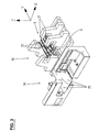
- the transfer device 8 shown in Fig. 1 comprises a support member 9 and a boom 10 which is movably received on the support member 9 and serves to support a glass sheet.
- the support member 9 includes a carriage 11 with a vertical support 12 and a transverse plate 13.
- the carriage 11 is movable by means of first drive means 16 along a support beam 6.
- first drive means 16 As a result, the transfer device 8 as a whole is displaceable back and forth in the y direction, as indicated by the double arrow 15 in FIG.
- the vertical support 12 with the transverse plate 13 and the arm 10 is movably received on the carriage 11 in height, as indicated in Fig. 1 by the double arrow 17.
- the adjustment of the height via second drive means 18, for example in the form of a pneumatic cylinder.
- the cantilever 10 extends in the horizontal direction and comprises cantilever elements 21 which serve to support a glass pane.
- the boom elements 21 are horizontally movable and beam-like shape.
- Fig. 1 shows as an example four boom elements 21, which are arranged side by side.
- the number of cantilever elements 21 may be adjusted to be two or more.
- the boom 10 is equipped with retaining means 22, which serve to hold a glass sheet during transfer. As a result, a relative movement between the glass pane and the arm 10 is avoided, so that the information about the spatial position of the glass pane from the information about the spatial position of the arm 10th results.
- the transfer device thus makes it possible to transfer the glass pane to a processing station in such a way that it can be processed without repositioning.
- holding means 22 e.g. Suction means, which are attached to the boom 10 and can be firmly sucked on the underside of the glass sheet by means of negative pressure.
- the two inner cantilever elements 21 are provided with retaining means 22.
- retention means 22 may be mounted on a single cantilever element, on a plurality of or on all cantilever elements.
- the support member 9 includes guides 23 which are fixed to the transverse plate 13 and the movement of the boom members 21 in the horizontal direction, i. pretend in y-direction according to FIG.
- the guides 23 are designed such that the arm 10 is displaceable back and forth in the y direction relative to the carrier part 9, as indicated by the double arrow 19 in FIG.
- the carrier part 9 For moving the boom 10 in the y-direction, the carrier part 9 comprises third drive means. As can be seen from Fig. 2, these include a motor 25 which is fixed below the transverse plate 13 and for driving a transverse to the boom 10 extending shaft 26 is used. The movement of the shaft 26 is transmitted by means of toothed belt 27 on pinion 28, which are arranged above the transverse plate 13, wherein in each case a pinion 28 acts on a rack 29 of a boom element 21. This coupling of the boom elements 21 to the motor 25 ensures that the boom elements 21 move synchronously in the same direction when actuated.
- FIG. 3 shows an example of a plant which comprises two processing stations 34 and 36 as well as a transfer device 8 arranged therebetween and which can be integrated in an overall plant.
- the processing station 34 is a grinding station for grinding the edge of a glass sheet
- the processing station 36 is a drilling station for mounting holes in the glass sheet.
- the processing stations 34 and 36 are provided with support elements 35 and 37, respectively, on which a glass pane rests with its underside during processing and which are arranged so that the jib elements 21 of the transfer device 8 can be guided therebetween.
- the support elements 35, 37 are at least partially equipped with suction means.
- the transfer device 8 is moved in the direction of the processing station 34 - according to FIG. 3 in the direction of the negative y-axis - to the end region of the support beam 6 and the boom 10 is extended by means of the third drive means 25-28.
- the boom elements 21 move relative to the support member 9, so that they can be passed between the support members 35, but without touching a lying thereon glass.
- the boom 10 is moved by means of the second drive means 18 up until the retaining means 22 can be attached to the glass pane underside. These are firmly sucked while the suction means of the support members 35 are released.
- the boom 10 is further up and together with the glass then proceed by means of the third drive means 25-28 in the direction of the positive y-axis.
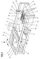
- Fig. 4 shows a system which can be integrated in an overall system and which contains a second embodiment 38 of the transfer device, wherein like parts are provided with the same reference numerals. In essence, the carrier parts of the two transfer devices 8 and 38 differ.
- the transverse plate 39 on which the extension arm 10 is movably received, is provided on both end sides via fourth drive means 40, each with a slide 41a or 41b connected.
- the fourth drive means 40 serve to adjust the boom 10 in height and are e.g. formed in the form of pneumatic cylinders.
- the carriage 41a or 41b includes fifth drive means 42a and 42b, so that it is guided by the support beams 43a, 43b in the y-direction movable.
- the plant according to FIG. 4 serves for cutting and breaking a glass pane and is arranged, for example, above for the plant according to FIG. 3 in an overall plant which serves for the production of glass panes of a certain shape, as used in particular in automobiles.
- the plant according to FIG. 4 comprises a cutting station 45 with a movable cutting head 53 and a sucker 54, a subsequent breaking station 46 with a breaking device 71, 72 and with a height-adjustable suction cup 77 and an endless conveyor belt 49. This serves on the one hand as a support surface 48 for the glass to be processed.
- the upper side 48 of the conveyor belt 49 can be moved in the y-direction so that the glass pane can be transported from the cutting station 45 to the breaking station 46 and then the broken glass shards from the breaking station 46 to a collecting container 84.
- the raw glass sheet is placed on the conveyor belt 49 at the cutting station 45 and while being held by the nipple 54, provided by the cutting head 53 with scribe lines according to the desired disk shape.
- the scratched glass pane is conveyed to the breaking station 46 by moving the conveyor belt 49, where the edge of the glass pane is broken off by means of the breaking device 71, 72.
- the broken-out useful part of the glass sheet is moved by means of the suction device 77 upwards, so that a gap between the glass sheet underside and the support surface 48 of the conveyor belt 49 is formed.
- the transfer device 38 is moved to the breaking station 46 and the boom 10 is extended relative to the transverse plate 39.
- the glass sheet is moved to the end of the system, where it can be transferred to another station, for example the grinding station 34.
- the transfer device and the method according to the invention have the advantage that during transfer, the upper side of a glass pane remains unaffected. This is especially beneficial when using the top with a layer which must not be injured.
- the transfer device and the method according to the invention are particularly suitable for processing coated glass panes, for example automobile windows.
Priority Applications (1)
| Application Number | Priority Date | Filing Date | Title |
|---|---|---|---|
| EP04405646A EP1647532A1 (fr) | 2004-10-15 | 2004-10-15 | Appareil et procédé de transfert de feuilles de verre |
Applications Claiming Priority (1)
| Application Number | Priority Date | Filing Date | Title |
|---|---|---|---|
| EP04405646A EP1647532A1 (fr) | 2004-10-15 | 2004-10-15 | Appareil et procédé de transfert de feuilles de verre |
Publications (1)
| Publication Number | Publication Date |
|---|---|
| EP1647532A1 true EP1647532A1 (fr) | 2006-04-19 |
Family
ID=34932321
Family Applications (1)
| Application Number | Title | Priority Date | Filing Date |
|---|---|---|---|
| EP04405646A Withdrawn EP1647532A1 (fr) | 2004-10-15 | 2004-10-15 | Appareil et procédé de transfert de feuilles de verre |
Country Status (1)
| Country | Link |
|---|---|
| EP (1) | EP1647532A1 (fr) |
Cited By (7)
| Publication number | Priority date | Publication date | Assignee | Title |
|---|---|---|---|---|
| WO2009056103A1 (fr) * | 2007-10-31 | 2009-05-07 | Grenzebach Maschinenbau Gmbh | Procédé et dispositif pour manipuler des plaques de verre sensibles aux chocs sans contamination dans des salles ultra-blanches |
| WO2009056101A1 (fr) * | 2007-10-31 | 2009-05-07 | Grenzebach Maschinenbau Gmbh | Dispositif et procédé pour orienter des plaques de verre sensibles aux chocs dans des salles ultra-blanches |
| DE202008008117U1 (de) * | 2008-06-19 | 2009-10-29 | Bc Prozesstechnik Gmbh | Vorrichtung zur Aufnahme und zum Transport von Profilen und flächigen Elementen |
| WO2010015943A2 (fr) * | 2008-08-05 | 2010-02-11 | Grenzebach Maschinenbau Gmbh | Procédé et dispositif pour couper des plaques de verre |
| WO2010025706A1 (fr) * | 2008-09-02 | 2010-03-11 | Grenzebach Maschinenbau Gmbh | Procédé et dispositif de stockage intermédiaire de plaques de verre pour modules photovoltaïques |
| WO2010015942A3 (fr) * | 2008-08-04 | 2010-06-03 | Grenzebach Maschinenbau Gmbh | Procédé et dispositif de production de modules photovoltaïques |
| CN103570233A (zh) * | 2013-11-27 | 2014-02-12 | 史国罕 | 玻璃切割刀盒调节装置 |
Citations (5)
| Publication number | Priority date | Publication date | Assignee | Title |
|---|---|---|---|---|
| JPH09183627A (ja) * | 1996-12-25 | 1997-07-15 | Casio Comput Co Ltd | ガラス切断方法およびその装置 |
| EP1101743A2 (fr) * | 1999-11-19 | 2001-05-23 | BOTTERO S.p.A. | Procédé et appareil pour la fabrication d' un article en verre plat ayant la majorité de sa surface recouverte d' un film de revêtement |
| JP2001180822A (ja) * | 1999-12-24 | 2001-07-03 | Kanegafuchi Chem Ind Co Ltd | 基板の受渡し方法及び装置 |
| JP2001237295A (ja) * | 2000-02-24 | 2001-08-31 | Canon Inc | 基板搬送用フィンガ |
| JP2001267393A (ja) * | 2000-03-22 | 2001-09-28 | Engineering System Kk | 搬送ロボット |
-
2004
- 2004-10-15 EP EP04405646A patent/EP1647532A1/fr not_active Withdrawn
Patent Citations (5)
| Publication number | Priority date | Publication date | Assignee | Title |
|---|---|---|---|---|
| JPH09183627A (ja) * | 1996-12-25 | 1997-07-15 | Casio Comput Co Ltd | ガラス切断方法およびその装置 |
| EP1101743A2 (fr) * | 1999-11-19 | 2001-05-23 | BOTTERO S.p.A. | Procédé et appareil pour la fabrication d' un article en verre plat ayant la majorité de sa surface recouverte d' un film de revêtement |
| JP2001180822A (ja) * | 1999-12-24 | 2001-07-03 | Kanegafuchi Chem Ind Co Ltd | 基板の受渡し方法及び装置 |
| JP2001237295A (ja) * | 2000-02-24 | 2001-08-31 | Canon Inc | 基板搬送用フィンガ |
| JP2001267393A (ja) * | 2000-03-22 | 2001-09-28 | Engineering System Kk | 搬送ロボット |
Non-Patent Citations (4)
| Title |
|---|
| PATENT ABSTRACTS OF JAPAN vol. 1997, no. 11 28 November 1997 (1997-11-28) * |
| PATENT ABSTRACTS OF JAPAN vol. 2000, no. 24 11 May 2001 (2001-05-11) * |
| PATENT ABSTRACTS OF JAPAN vol. 2000, no. 25 12 April 2001 (2001-04-12) * |
| PATENT ABSTRACTS OF JAPAN vol. 2000, no. 26 1 July 2002 (2002-07-01) * |
Cited By (14)
| Publication number | Priority date | Publication date | Assignee | Title |
|---|---|---|---|---|
| US8360226B2 (en) | 2007-10-31 | 2013-01-29 | Grenzebach Maschinenbau Gmbh | Method and apparatus for the contamination-free treatment of shock-sensitive glass plates in ultra clean rooms |
| WO2009056101A1 (fr) * | 2007-10-31 | 2009-05-07 | Grenzebach Maschinenbau Gmbh | Dispositif et procédé pour orienter des plaques de verre sensibles aux chocs dans des salles ultra-blanches |
| WO2009056103A1 (fr) * | 2007-10-31 | 2009-05-07 | Grenzebach Maschinenbau Gmbh | Procédé et dispositif pour manipuler des plaques de verre sensibles aux chocs sans contamination dans des salles ultra-blanches |
| US8360227B2 (en) | 2007-10-31 | 2013-01-29 | Grenzebach Maschinenbau Gmbh | Apparatus and method for orienting shock-sensitive glass plates in ultra clean rooms |
| DE202008008117U1 (de) * | 2008-06-19 | 2009-10-29 | Bc Prozesstechnik Gmbh | Vorrichtung zur Aufnahme und zum Transport von Profilen und flächigen Elementen |
| US8646170B2 (en) | 2008-08-04 | 2014-02-11 | Grenzebach Maschinenbau Gmbh | Device for producing photovoltaic modules |
| WO2010015942A3 (fr) * | 2008-08-04 | 2010-06-03 | Grenzebach Maschinenbau Gmbh | Procédé et dispositif de production de modules photovoltaïques |
| WO2010015943A3 (fr) * | 2008-08-05 | 2010-04-08 | Grenzebach Maschinenbau Gmbh | Procédé et dispositif pour couper des plaques de verre |
| WO2010015943A2 (fr) * | 2008-08-05 | 2010-02-11 | Grenzebach Maschinenbau Gmbh | Procédé et dispositif pour couper des plaques de verre |
| WO2010025706A1 (fr) * | 2008-09-02 | 2010-03-11 | Grenzebach Maschinenbau Gmbh | Procédé et dispositif de stockage intermédiaire de plaques de verre pour modules photovoltaïques |
| US8870515B2 (en) | 2008-09-02 | 2014-10-28 | Grenzebach Maschinebau Gmbh | Method and device for storing glass plates for photovoltaic modules |
| CN102186753B (zh) * | 2008-09-02 | 2015-07-29 | 格林策巴赫机械制造有限公司 | 暂时储存光生伏打模块玻璃板的方法及装置 |
| CN103570233A (zh) * | 2013-11-27 | 2014-02-12 | 史国罕 | 玻璃切割刀盒调节装置 |
| CN103570233B (zh) * | 2013-11-27 | 2015-12-30 | 史国罕 | 玻璃切割刀盒调节装置 |
Similar Documents
| Publication | Publication Date | Title |
|---|---|---|
| DE4123929C2 (de) | Verfahren und Vorrichtung zum Zerteilen von Flachglastafeln | |
| EP1562870B1 (fr) | Dispositif et procede pour deplacer des plaques de verre lors de l'usinage de ces dernieres | |
| EP1967301B1 (fr) | Agencement mécanique destiné au traitement de pièces à usiner de type plaques à l'aide d'un dispositif de traitement tout comme avec un dispositif de manipulation pour produits de traitement | |
| EP0252871A1 (fr) | Robot industriel | |
| EP3283240B1 (fr) | Plateau de réception pour machine de cintrage | |
| EP1647534B1 (fr) | Dispositif et procédé pour ouvrir le trait de coupe de feuilles de verre | |
| EP2484483B1 (fr) | Unité d'amenée et de chargement | |
| WO2003070420A1 (fr) | Dispositif d'alimentation pour acheminer des porte-pieces dans le sens longitudinal d'un convoyeur a courroie vers un poste d'usinage | |
| WO1998014288A1 (fr) | Machine a usiner | |
| EP2361709A2 (fr) | Dispositif d'alimentation de panneaux | |
| EP1647532A1 (fr) | Appareil et procédé de transfert de feuilles de verre | |
| DE19858791B4 (de) | Plattenbearbeitungsmaschine | |
| DE3345920A1 (de) | Einrichtung zum automatischen transport von werkstuecken | |
| DE1201245B (de) | Vorrichtung zum Foerdern eines Werkstueckes | |
| DE60021833T2 (de) | Vorrichtung zur Entfernung von Ausbrechteilen | |
| EP2274114B1 (fr) | Dispositif de transport avec butée de positionnement | |
| EP1845068A1 (fr) | Dispositif d'usinage de feuilles de verre | |
| CH694585A5 (de) | Vorrichtung zum Ausrichten von Glasscheiben auf einem Rollenförderer eines Glühkühlofens. | |
| DE19700950A1 (de) | Verfahren und Vorrichtung zum Abbrechen der Randstreifen einer nach einem vorgegebenen Umriß auf einem Glasscheibenrohling eingeritzten Glasscheibe | |
| AT399144B (de) | Verfahren und vorrichtung zum brechen von glastafeln | |
| EP0597386B1 (fr) | Dispositif pour transférer des tÔles dans une installation de presse | |
| EP1647533A1 (fr) | Dispositif pour travailler de plaques de verre | |
| DE102018123907B4 (de) | Vorrichtung zum Abheben eines plattenförmigen obersten Werkstücks von einem Werkstückstapel | |
| EP2085178B1 (fr) | Dispositif de transfert et de transmission de pièces usinées et/ou des outils agencés sur des supports | |
| DE3246720A1 (de) | Vorrichtung fuer die manipulation von pressgut im zuge der herstellung und/oder verguetung von spanplatten, faserplatten u. dgl. |
Legal Events
| Date | Code | Title | Description |
|---|---|---|---|
| PUAI | Public reference made under article 153(3) epc to a published international application that has entered the european phase |
Free format text: ORIGINAL CODE: 0009012 |
|
| AK | Designated contracting states |
Kind code of ref document: A1 Designated state(s): AT BE BG CH CY CZ DE DK EE ES FI FR GB GR HU IE IT LI LU MC NL PL PT RO SE SI SK TR |
|
| AX | Request for extension of the european patent |
Extension state: AL HR LT LV MK |
|
| 17P | Request for examination filed |
Effective date: 20061006 |
|
| AKX | Designation fees paid |
Designated state(s): AT BE BG CH CY CZ DE DK EE ES FI FR GB GR HU IE IT LI LU MC NL PL PT RO SE SI SK TR |
|
| 17Q | First examination report despatched |
Effective date: 20070321 |
|
| STAA | Information on the status of an ep patent application or granted ep patent |
Free format text: STATUS: THE APPLICATION IS DEEMED TO BE WITHDRAWN |
|
| 18D | Application deemed to be withdrawn |
Effective date: 20070801 |