EP1647532A1 - Transfer apparatus and process for transferring sheets of glass - Google Patents
Transfer apparatus and process for transferring sheets of glass Download PDFInfo
- Publication number
- EP1647532A1 EP1647532A1 EP04405646A EP04405646A EP1647532A1 EP 1647532 A1 EP1647532 A1 EP 1647532A1 EP 04405646 A EP04405646 A EP 04405646A EP 04405646 A EP04405646 A EP 04405646A EP 1647532 A1 EP1647532 A1 EP 1647532A1
- Authority
- EP
- European Patent Office
- Prior art keywords
- boom
- station
- glass pane
- glass
- movable
- Prior art date
- Legal status (The legal status is an assumption and is not a legal conclusion. Google has not performed a legal analysis and makes no representation as to the accuracy of the status listed.)
- Withdrawn
Links
Images

Classifications
-
- C—CHEMISTRY; METALLURGY
- C03—GLASS; MINERAL OR SLAG WOOL
- C03B—MANUFACTURE, SHAPING, OR SUPPLEMENTARY PROCESSES
- C03B33/00—Severing cooled glass
- C03B33/02—Cutting or splitting sheet glass or ribbons; Apparatus or machines therefor
- C03B33/023—Cutting or splitting sheet glass or ribbons; Apparatus or machines therefor the sheet or ribbon being in a horizontal position
- C03B33/03—Glass cutting tables; Apparatus for transporting or handling sheet glass during the cutting or breaking operations
-
- B—PERFORMING OPERATIONS; TRANSPORTING
- B65—CONVEYING; PACKING; STORING; HANDLING THIN OR FILAMENTARY MATERIAL
- B65G—TRANSPORT OR STORAGE DEVICES, e.g. CONVEYORS FOR LOADING OR TIPPING, SHOP CONVEYOR SYSTEMS OR PNEUMATIC TUBE CONVEYORS
- B65G49/00—Conveying systems characterised by their application for specified purposes not otherwise provided for
- B65G49/05—Conveying systems characterised by their application for specified purposes not otherwise provided for for fragile or damageable materials or articles
- B65G49/06—Conveying systems characterised by their application for specified purposes not otherwise provided for for fragile or damageable materials or articles for fragile sheets, e.g. glass
- B65G49/061—Lifting, gripping, or carrying means, for one or more sheets forming independent means of transport, e.g. suction cups, transport frames
-
- B—PERFORMING OPERATIONS; TRANSPORTING
- B65—CONVEYING; PACKING; STORING; HANDLING THIN OR FILAMENTARY MATERIAL
- B65G—TRANSPORT OR STORAGE DEVICES, e.g. CONVEYORS FOR LOADING OR TIPPING, SHOP CONVEYOR SYSTEMS OR PNEUMATIC TUBE CONVEYORS
- B65G2249/00—Aspects relating to conveying systems for the manufacture of fragile sheets
- B65G2249/04—Arrangements of vacuum systems or suction cups
Definitions
- the invention relates to a transfer device for transferring glass sheets according to the preamble of the device claim 1 and a method according to the preamble of the independent method claim.
- the present invention based on the object to provide a transfer device and a method, which or which transferring a glass sheet so allows it to be touched only on the side on which it rests at a work station.
- the device and method according to the invention have i.a. the advantage that when transferring a glass pane only that side is touched, on which it rests at a processing station. This is particularly advantageous for glass panes coated on one side, since the sensitive layer remains untouched during transfer.
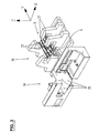
- the transfer device 8 shown in Fig. 1 comprises a support member 9 and a boom 10 which is movably received on the support member 9 and serves to support a glass sheet.
- the support member 9 includes a carriage 11 with a vertical support 12 and a transverse plate 13.
- the carriage 11 is movable by means of first drive means 16 along a support beam 6.
- first drive means 16 As a result, the transfer device 8 as a whole is displaceable back and forth in the y direction, as indicated by the double arrow 15 in FIG.
- the vertical support 12 with the transverse plate 13 and the arm 10 is movably received on the carriage 11 in height, as indicated in Fig. 1 by the double arrow 17.
- the adjustment of the height via second drive means 18, for example in the form of a pneumatic cylinder.
- the cantilever 10 extends in the horizontal direction and comprises cantilever elements 21 which serve to support a glass pane.
- the boom elements 21 are horizontally movable and beam-like shape.
- Fig. 1 shows as an example four boom elements 21, which are arranged side by side.
- the number of cantilever elements 21 may be adjusted to be two or more.
- the boom 10 is equipped with retaining means 22, which serve to hold a glass sheet during transfer. As a result, a relative movement between the glass pane and the arm 10 is avoided, so that the information about the spatial position of the glass pane from the information about the spatial position of the arm 10th results.
- the transfer device thus makes it possible to transfer the glass pane to a processing station in such a way that it can be processed without repositioning.
- holding means 22 e.g. Suction means, which are attached to the boom 10 and can be firmly sucked on the underside of the glass sheet by means of negative pressure.
- the two inner cantilever elements 21 are provided with retaining means 22.
- retention means 22 may be mounted on a single cantilever element, on a plurality of or on all cantilever elements.
- the support member 9 includes guides 23 which are fixed to the transverse plate 13 and the movement of the boom members 21 in the horizontal direction, i. pretend in y-direction according to FIG.
- the guides 23 are designed such that the arm 10 is displaceable back and forth in the y direction relative to the carrier part 9, as indicated by the double arrow 19 in FIG.
- the carrier part 9 For moving the boom 10 in the y-direction, the carrier part 9 comprises third drive means. As can be seen from Fig. 2, these include a motor 25 which is fixed below the transverse plate 13 and for driving a transverse to the boom 10 extending shaft 26 is used. The movement of the shaft 26 is transmitted by means of toothed belt 27 on pinion 28, which are arranged above the transverse plate 13, wherein in each case a pinion 28 acts on a rack 29 of a boom element 21. This coupling of the boom elements 21 to the motor 25 ensures that the boom elements 21 move synchronously in the same direction when actuated.
- FIG. 3 shows an example of a plant which comprises two processing stations 34 and 36 as well as a transfer device 8 arranged therebetween and which can be integrated in an overall plant.
- the processing station 34 is a grinding station for grinding the edge of a glass sheet
- the processing station 36 is a drilling station for mounting holes in the glass sheet.
- the processing stations 34 and 36 are provided with support elements 35 and 37, respectively, on which a glass pane rests with its underside during processing and which are arranged so that the jib elements 21 of the transfer device 8 can be guided therebetween.
- the support elements 35, 37 are at least partially equipped with suction means.
- the transfer device 8 is moved in the direction of the processing station 34 - according to FIG. 3 in the direction of the negative y-axis - to the end region of the support beam 6 and the boom 10 is extended by means of the third drive means 25-28.
- the boom elements 21 move relative to the support member 9, so that they can be passed between the support members 35, but without touching a lying thereon glass.
- the boom 10 is moved by means of the second drive means 18 up until the retaining means 22 can be attached to the glass pane underside. These are firmly sucked while the suction means of the support members 35 are released.
- the boom 10 is further up and together with the glass then proceed by means of the third drive means 25-28 in the direction of the positive y-axis.
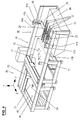
- Fig. 4 shows a system which can be integrated in an overall system and which contains a second embodiment 38 of the transfer device, wherein like parts are provided with the same reference numerals. In essence, the carrier parts of the two transfer devices 8 and 38 differ.
- the transverse plate 39 on which the extension arm 10 is movably received, is provided on both end sides via fourth drive means 40, each with a slide 41a or 41b connected.
- the fourth drive means 40 serve to adjust the boom 10 in height and are e.g. formed in the form of pneumatic cylinders.
- the carriage 41a or 41b includes fifth drive means 42a and 42b, so that it is guided by the support beams 43a, 43b in the y-direction movable.
- the plant according to FIG. 4 serves for cutting and breaking a glass pane and is arranged, for example, above for the plant according to FIG. 3 in an overall plant which serves for the production of glass panes of a certain shape, as used in particular in automobiles.
- the plant according to FIG. 4 comprises a cutting station 45 with a movable cutting head 53 and a sucker 54, a subsequent breaking station 46 with a breaking device 71, 72 and with a height-adjustable suction cup 77 and an endless conveyor belt 49. This serves on the one hand as a support surface 48 for the glass to be processed.
- the upper side 48 of the conveyor belt 49 can be moved in the y-direction so that the glass pane can be transported from the cutting station 45 to the breaking station 46 and then the broken glass shards from the breaking station 46 to a collecting container 84.
- the raw glass sheet is placed on the conveyor belt 49 at the cutting station 45 and while being held by the nipple 54, provided by the cutting head 53 with scribe lines according to the desired disk shape.
- the scratched glass pane is conveyed to the breaking station 46 by moving the conveyor belt 49, where the edge of the glass pane is broken off by means of the breaking device 71, 72.
- the broken-out useful part of the glass sheet is moved by means of the suction device 77 upwards, so that a gap between the glass sheet underside and the support surface 48 of the conveyor belt 49 is formed.
- the transfer device 38 is moved to the breaking station 46 and the boom 10 is extended relative to the transverse plate 39.
- the glass sheet is moved to the end of the system, where it can be transferred to another station, for example the grinding station 34.
- the transfer device and the method according to the invention have the advantage that during transfer, the upper side of a glass pane remains unaffected. This is especially beneficial when using the top with a layer which must not be injured.
- the transfer device and the method according to the invention are particularly suitable for processing coated glass panes, for example automobile windows.
Abstract
Description
Die Erfindung bezieht sich auf eine Transfervorrichtung zum Transferieren von Glasscheiben gemäss Oberbegriff des Vorrichtungsanspruchs 1 und ein Verfahren gemäss Oberbegriff des unabhängigen Verfahrensanspruchs.The invention relates to a transfer device for transferring glass sheets according to the preamble of the device claim 1 and a method according to the preamble of the independent method claim.
Die Herstellung von Glasscheiben mit einer bestimmten Form erfordert mehrere, an verschiedenen Bearbeitungsstationen durchzuführende Arbeitsschritte wie Ritzen, Brechen und Schleifen. Um eine Beschädigung zu vermeiden, ist beim Transfer zwischen den Bearbeitungsstationen eine vorsichtige Handhabung zu gewährleisten, insbesondere dann, wenn die Glasscheiben, wie sie u.a. in Automobilen verwendet werden, mit einer empfindlichen Schicht versehen sind.The production of glass sheets with a certain shape requires several steps to be performed at different processing stations such as scribing, breaking and grinding. To avoid damage, careful handling should be ensured during transfer between processing stations, especially if the glass panes, such used in automobiles are provided with a sensitive layer.
Aus der Patentschrift CH-A5-686 572 ist es bekannt, zum Transferieren einer Glasscheibe von der einen Bearbeitungsstation zur nächsten einen verfahrbaren Saugteller zu verwenden, der auf die Oberseite der Glasscheibe anbringbar ist. Da diese beim Bearbeiten in der Regel mit ihrer Unterseite aufliegt, wird die Glasscheibe beim Herstellungsprozess insgesamt sowohl auf der Ober- wie Unterseite berührt. Dies ist besonders nachteilig bei der Bearbeitung von Glasscheiben mit einer beschichteten Oberseite, da diese mit dem Saugteller in Kontakt kommt und eine Beschädigung - wenn auch nur geringe - unvermeidlich ist.From the patent CH-A5-686 572 it is known to use for transferring a glass sheet from one processing station to the next a movable suction plate which is attachable to the top of the glass sheet. Since this usually rests with its underside during processing, the glass pane is touched in the manufacturing process as a whole both on the top and bottom. This is particularly disadvantageous in the processing of glass sheets with a coated top, since this comes into contact with the suction cup and damage - albeit small - is inevitable.
Ausgehend von diesem Stand der Technik liegt der vorliegenden Erfindung die Aufgabe zu Grunde, eine Transfervorrichtung sowie ein Verfahren anzugeben, welche bzw. welches das Transferieren einer Glasscheibe so ermöglicht, dass sie lediglich auf der Seite berührt wird, auf welcher sie bei einer Bearbeitungsstation aufliegt.Based on this prior art, the present invention based on the object to provide a transfer device and a method, which or which transferring a glass sheet so allows it to be touched only on the side on which it rests at a work station.
Diese Aufgabe wird durch die erfindungsgemässe Transfervorrichtung gemäss Anspruch 1 sowie durch das erfindungsgemässe Verfahren gemäss dem unabhängigem Verfahrensanspruch gelöst. Die weiteren Ansprüche geben bevorzugte Ausführungen an sowie eine Anlage mit einer erfindungsgemässen Transfervorrichtung.This object is achieved by the inventive transfer device according to claim 1 and by the inventive method according to the independent method claim. The further claims indicate preferred embodiments as well as a system with a transfer device according to the invention.
Die Vorrichtung und das Verfahren gemäss der Erfindung haben u.a. den Vorteil, dass beim Transferieren einer Glasscheibe nur diejenige Seite berührt wird, auf welcher sie bei einer Bearbeitungsstation aufliegt. Dies ist besonders vorteilhaft bei einseitig beschichteten Glasscheiben, da beim Transferieren die empfindliche Schicht unberührt bleibt.The device and method according to the invention have i.a. the advantage that when transferring a glass pane only that side is touched, on which it rests at a processing station. This is particularly advantageous for glass panes coated on one side, since the sensitive layer remains untouched during transfer.
Die Erfindung wird im Folgenden anhand eines Ausführungsbeispiels unter Bezugnahme auf Figuren erläutert.
Es zeigen:
- Fig. 1 eine perspektivische Ansicht einer erfindungsgemässen Transfervorrichtung;
- Fig. 2 eine Vorderansicht der erfindungsgemässen Transfervorrichtung gemäss Fig. 1;
- Fig. 3 einen ersten Teil einer Gesamtanlage mit zwei Bearbeitungsstationen und einer erfindungsgemässen Transfervorrichtung gemäss Fig. 1; und
- Fig. 4 einen zweiten Teil einer Gesamtanlage mit zwei Bearbeitungsstationen und einer weiteren Ausführungsform der erfindungsgemässen Transfervorrichtung gemäss Fig. 1.
Show it:
- 1 is a perspective view of a transfer device according to the invention;
- FIG. 2 shows a front view of the transfer device according to the invention according to FIG. 1; FIG.
- 3 shows a first part of an overall system with two processing stations and a transfer device according to the invention according to FIG. 1; and
- 4 shows a second part of an overall system with two processing stations and a further embodiment of the transfer device according to the invention according to FIG. 1.
Die in Fig. 1 gezeigte Transfervorrichtung 8 umfasst ein Trägerteil 9 und einen Ausleger 10, der verfahrbar am Trägerteil 9 aufgenommen ist und zum Stützen einer Glasscheibe dient.The
Das Trägerteil 9 enthält einen Schlitten 11 mit einem Vertikalträger 12 und einer Querplatte 13. Der Schlitten 11 ist mittels ersten Antriebsmittel 16 entlang einem Trägerbalken 6 verfahrbar. Dadurch ist die Transfervorrichtung 8 als Ganzes in der y-Richtung hin und her verschiebbar, wie dies in der Fig. 1 durch den Doppelpfeil 15 angedeutet ist. Der Vertikalträger 12 mit der Querplatte 13 und dem Ausleger 10 ist am Schlitten 11 in der Höhe verfahrbar aufgenommen, wie dies in der Fig. 1 durch den Doppelpfeil 17 angedeutet ist. Das Einstellen der Höhe erfolgt über zweite Antriebsmittel 18 beispielsweise in Form eines pneumatischen Zylinders.The
Der Ausleger 10 erstreckt sich in horizontaler Richtung und umfasst Auslegerelemente 21, welche zum Stützen einer Glasscheibe dienen. Die Auslegerelemente 21 sind horizontal verfahrbar und von balkenähnlicher Form. Fig. 1 zeigt als Beispiel vier Auslegerelemente 21, die nebeneinander angeordnet sind. Je nach Anwendung kann natürlich die Anzahl der Auslegerelemente 21 angepasst sein und zwei oder mehr betragen.The
Der Ausleger 10 ist mit Festhaltemitteln 22 ausgerüstet, welche dazu dienen, eine Glasscheibe beim Transferieren festzuhalten. Dadurch wird eine Relativbewegung zwischen Glasscheibe und Ausleger 10 vermieden, sodass sich die Information über die räumliche Position der Glasscheibe aus der Information über die räumliche Position des Auslegers 10 ergibt. Die Transfervorrichtung erlaubt es demnach, einer Bearbeitungsstation die Glasscheibe so zu übergeben, dass diese ohne Neupositionieren bearbeitet werden kann.The
Als Festhaltemittel 22 eignen sich z.B. Saugmittel, welche am Ausleger 10 angebracht sind und auf der Unterseite der Glasscheibe mittels Unterdruck festgesaugt werden können. In der in den Figuren 1 und 2 gezeigten Ausführungsform sind die beiden inneren Auslegerelemente 21 mit Festhaltemitteln 22 versehen. Natürlich können Festhaltemittel 22 je nach Anzahl der Auslegerelemente 21 und nach Anwendungszweck der Transfervorrichtung 8 an einem einzelnen Auslegerelement, an mehreren oder an allen Auslegerelementen angebracht sein.As holding means 22, e.g. Suction means, which are attached to the
Das Trägerteil 9 umfasst Führungen 23, die an der Querplatte 13 befestigt sind und die Bewegung der Auslegerelemente 21 in horizontaler Richtung, d.h. gemäss Fig. 1 in y-Richtung vorgeben. Die Führungen 23 sind so ausgebildet, dass der Ausleger 10 in Bezug auf das Trägerteil 9 in y-Richtung hin und her verschiebbar ist, wie dies in der Fig. 1 durch den Doppelpfeil 19 angedeutet ist.The
Zum Verfahren des Auslegers 10 in y-Richtung umfasst das Trägerteil 9 dritte Antriebsmittel. Wie aus der Fig. 2 ersichtlich, enthalten diese einen Motor 25, der unterhalb der Querplatte 13 befestigt ist und zum Antreiben einer quer zum Ausleger 10 verlaufenden Welle 26 dient. Die Bewegung der Welle 26 wird mittels Zahnriemen 27 auf Ritzel 28 übertragen, die oberhalb der Querplatte 13 angeordnet sind, wobei jeweils ein Ritzel 28 auf eine Zahnstange 29 eines Auslegerelements 21 wirkt. Durch diese Kopplung der Auslegerelemente 21 an den Motor 25 ist gewährleistet, dass sich bei dessen Betätigung die Auslegerelemente 21 synchron in dieselbe Richtung bewegen.For moving the
Fig. 3 zeigt ein Beispiel einer Anlage, welche zwei Bearbeitungsstationen 34 und 36 sowie eine dazwischen angeordnete Transfervorrichtung 8 umfasst und welche in einer Gesamtanlage integriert sein kann. Die Bearbeitungsstation 34 ist eine Schleifstation zum Schleifen des Randes einer Glasscheibe, die Bearbeitungsstation 36 ist eine Bohrstation zum Anbringen von Löchern in der Glasscheibe. Die Bearbeitungsstationen 34 und 36 sind mit Stützelementen 35 bzw. 37 versehen, auf welcher eine Glasscheibe bei der Bearbeitung mit ihrer Unterseite aufliegt und welche so angeordnet sind, dass die Auslegerelemente 21 der Transfervorrichtung 8 dazwischengeführt werden können. Zum Festhalten der Glasscheibe während der Bearbeitung sind die Stützelemente 35, 37 zumindest teilweise mit Saugmitteln ausgerüstet.3 shows an example of a plant which comprises two
Die Transfervorrichtung 8 wird in Richtung der Bearbeitungsstation 34 - gemäss Fig. 3 in Richtung der negativen y-Achse - bis zum Endbereich des Trägerbalkens 6 verfahren und der Ausleger 10 mittels der dritten Antriebsmittel 25-28 ausgefahren. Dabei bewegen sich die Auslegerelemente 21 relativ zum Trägerteil 9, sodass sie zwischen den Stützelementen 35 hindurchgeführt werden können, ohne jedoch eine darauf liegende Glasscheibe zu berühren. Der Ausleger 10 wird mittels der zweiten Antriebsmittel 18 nach oben verfahren, bis die Festhaltemittel 22 an der Glasscheibenunterseite angebracht werden können. Diese werden festgesaugt, während die Saugmittel der Stützelemente 35 gelöst werden. Der Ausleger 10 wird zusammen mit der Glasscheibe weiter nach oben und anschliessend mittels der dritten Antriebsmittel 25-28 in Richtung der positiven y-Achse verfahren.The
Zum Übergeben der Glasscheibe an die Bearbeitungsstation 36 wird in analoger Weise vorgegangen: Verfahren der Transfervorrichtung 8 bis zum Endbereich des Trägerbalkens 6 und Ausfahren des Auslegers 10 mittels der dritten Antriebsmittel 25-28 sowie anschliessendes Absenken des Auslegers 10 und Lösen der Festhaltemittel 22.To transfer the glass sheet to the
Fig. 4 zeigt eine Anlage, welche in einer Gesamtanlage integriert sein kann und welche eine zweite Ausführungsform 38 der Transfervorrichtung enthält, wobei gleiche Teile mit gleichen Bezugszeichen versehen sind. Im Wesentlichen unterscheiden sich die Trägerteile der beiden Transfervorrichtungen 8 und 38. Bei der Transfervorrichtung 38 gemäss Fig. 4 ist die Querplatte 39, an welchem der Ausleger 10 verfahrbar aufgenommen ist, an beiden Endseiten über vierte Antriebsmittel 40 jeweils mit einem Schlitten 41a bzw. 41b verbunden. Die vierten Antriebsmittel 40 dienen dazu, den Ausleger 10 in der Höhe zu verstellen und sind z.B. in Form von pneumatischen Zylindern ausgebildet. Der Schlitten 41a bzw. 41b enthält fünfte Antriebsmittel 42a bzw. 42b, sodass er geführt durch die Trägerbalken 43a, 43b in y-Richtung verfahrbar ist.Fig. 4 shows a system which can be integrated in an overall system and which contains a
Die Anlage gemäss Fig. 4 dient zum Schneiden und Brechen einer Glasscheibe und ist z.B. vorangehend zur Anlage gemäss Fig. 3 in einer Gesamtanlage angeordnet, die zur Herstellung von Glasscheiben bestimmter Form dient, wie sie insbesondere in Automobilen verwendet werden. Die Anlage gemäss Fig. 4 umfasst eine Schneidstation 45 mit einem verfahrbaren Schneidkopf 53 und einem Sauger 54, eine anschliessende Brechstation 46 mit einer Brechvorrichtung 71, 72 und mit einem in der Höhe verstellbaren Sauger 77 sowie ein endloses Förderband 49. Dieses dient einerseits als Auflagefläche 48 für die zu bearbeitende Glasscheibe. Andererseits ist die Oberseite 48 des Förderbandes 49 in y-Richtung verfahrbar, sodass die Glasscheibe von der Schneidstation 45 zur Brechstation 46 und anschliessend die abgebrochenen Glasscherben von der Brechstation 46 zu einem Auffangbehälter 84 transportiert werden können.The plant according to FIG. 4 serves for cutting and breaking a glass pane and is arranged, for example, above for the plant according to FIG. 3 in an overall plant which serves for the production of glass panes of a certain shape, as used in particular in automobiles. The plant according to FIG. 4 comprises a
Für die Bearbeitung wird die rohe Glasscheibe auf das Förderband 49 bei der Schneidstation 45 gelegt und während sie durch den Sauger 54 festgehalten wird, mittels des Schneidkopfs 53 mit Ritzlinien gemäss der gewünschten Scheibenform versehen. Anschliessend wird durch Verfahren des Förderbandes 49 die geritzte Glasscheibe zur Brechstation 46 befördert, wo mittels der Brechvorrichtung 71, 72 der Rand der Glasscheibe abgebrochen wird. Der herausgebrochene Nutzteil der Glasscheibe wird mittels des Saugers 77 nach oben bewegt, sodass sich ein Zwischenraum zwischen der Glasscheibenunterseite und der Auflagefläche 48 des Förderbandes 49 bildet. Die Transfervorrichtung 38 wird zur Brechstation 46 hin verfahren und der Ausleger 10 relativ zur Querplatte 39 ausgefahren. Diese wird angehoben, die Festhaltemittel 22 an der Glasscheibenunterseite angebracht und der Sauger 77 gelöst. Durch Verfahren des Auslegers 10 sowie der Transfervorrichtung 38 insgesamt wird die Glasscheibe an das Ende der Anlage verschoben, wo sie einer weiteren Station, beispielsweise der Schleifstation 34 übergeben werden kann.For processing, the raw glass sheet is placed on the
Die Transfervorrichtung sowie das Verfahren gemäss der Erfindung haben den Vorteil, dass beim Transferieren die Oberseite einer Glasscheibe unberührt bleibt. Dies ist besonders vorteilhaft, wenn die Oberseite mit einer Schicht versehen ist, die nicht verletzt werden darf. So eignet sich die Transfervorrichtung sowie das Verfahren gemäss der Erfindung insbesondere zur Bearbeitung von beschichteten Glasscheiben, beispielsweise Automobilscheiben.The transfer device and the method according to the invention have the advantage that during transfer, the upper side of a glass pane remains unaffected. This is especially beneficial when using the top with a layer which must not be injured. Thus, the transfer device and the method according to the invention are particularly suitable for processing coated glass panes, for example automobile windows.
Claims (11)
einen Ausleger (10), welcher verfahrbar am Trägerteil (9, 39) angeordnet ist.Transfer device for transferring a glass pane with a movable carrier part, characterized by
a boom (10) which is arranged to be movable on the carrier part (9, 39).
vorzugsweise mindestens einer der beiden Stationen (46; 34, 36) Hebemittel zum Heben (77) einer Glasscheibe und/oder Stützelemente (35, 37) umfasst, die so angeordnet sind, dass der Ausleger (10) dazwischengeführt werden kann.Plant with at least two stations and an interposed device according to one of claims 1 to 5, wherein
preferably at least one of the two stations (46; 34, 36) comprises lifting means for lifting (77) a glass pane and / or supporting elements (35, 37) arranged so that the jib (10) can be passed therebetween.
die Glasscheibe an der ersten Station übernommen wird, indem ein Ausleger (10) unter die Glasscheibe gefahren und angehoben wird, und der Ausleger zusammen mit der auf ihm ruhenden Glasscheibe zur zweiten Station verfahren wird.Method for transferring a glass pane from a first station (34; 46) to a bearing surface (35; 48), on which the glass pane rests with its lower side, to a second station (36; 34), characterized in that
the glass pane is taken over at the first station by moving a jib (10) under the glass pane and lifting it, and moving the jib together with the glass pane resting on it to the second station.
vorzugsweise die Richtung (19), in welche der Ausleger (10) bei der ersten Station (34; 46) ausgefahren wird, im Wesentlichen parallel zur Verfahrrichtung ist, in welche der Ausleger zusammen mit der Glasscheibe verfahren wird.Method according to one of claims 8 to 9, characterized in that the glass pane is taken and moved in a horizontal position and that
Preferably, the direction (19), in which the boom (10) at the first station (34, 46) is extended, is substantially parallel to the direction in which the boom is moved together with the glass.
Priority Applications (1)
| Application Number | Priority Date | Filing Date | Title |
|---|---|---|---|
| EP04405646A EP1647532A1 (en) | 2004-10-15 | 2004-10-15 | Transfer apparatus and process for transferring sheets of glass |
Applications Claiming Priority (1)
| Application Number | Priority Date | Filing Date | Title |
|---|---|---|---|
| EP04405646A EP1647532A1 (en) | 2004-10-15 | 2004-10-15 | Transfer apparatus and process for transferring sheets of glass |
Publications (1)
| Publication Number | Publication Date |
|---|---|
| EP1647532A1 true EP1647532A1 (en) | 2006-04-19 |
Family
ID=34932321
Family Applications (1)
| Application Number | Title | Priority Date | Filing Date |
|---|---|---|---|
| EP04405646A Withdrawn EP1647532A1 (en) | 2004-10-15 | 2004-10-15 | Transfer apparatus and process for transferring sheets of glass |
Country Status (1)
| Country | Link |
|---|---|
| EP (1) | EP1647532A1 (en) |
Cited By (7)
| Publication number | Priority date | Publication date | Assignee | Title |
|---|---|---|---|---|
| WO2009056103A1 (en) * | 2007-10-31 | 2009-05-07 | Grenzebach Maschinenbau Gmbh | Method and apparatus for the contamination-free treatment of shock-sensitive glass plates in ultra clean rooms |
| WO2009056101A1 (en) * | 2007-10-31 | 2009-05-07 | Grenzebach Maschinenbau Gmbh | Apparatus and method for orienting shock-sensitive glass plates in ultra clean rooms |
| DE202008008117U1 (en) * | 2008-06-19 | 2009-10-29 | Bc Prozesstechnik Gmbh | Device for receiving and transporting profiles and flat elements |
| WO2010015943A2 (en) * | 2008-08-05 | 2010-02-11 | Grenzebach Maschinenbau Gmbh | Device and method for cutting glass panes |
| WO2010025706A1 (en) * | 2008-09-02 | 2010-03-11 | Grenzebach Maschinenbau Gmbh | Method and device for temporarily storing glass plates for photovoltaic modules |
| WO2010015942A3 (en) * | 2008-08-04 | 2010-06-03 | Grenzebach Maschinenbau Gmbh | Method and device for producing photovoltaic modules |
| CN103570233A (en) * | 2013-11-27 | 2014-02-12 | 史国罕 | Glass cutter knife box regulating device |
Citations (5)
| Publication number | Priority date | Publication date | Assignee | Title |
|---|---|---|---|---|
| JPH09183627A (en) * | 1996-12-25 | 1997-07-15 | Casio Comput Co Ltd | Method for cutting glass and device therefor |
| EP1101743A2 (en) * | 1999-11-19 | 2001-05-23 | BOTTERO S.p.A. | Method and machine for producing a flat glass article having an extensive surface covered with a layer of covering material |
| JP2001180822A (en) * | 1999-12-24 | 2001-07-03 | Kanegafuchi Chem Ind Co Ltd | Method and device for delivering substrate |
| JP2001237295A (en) * | 2000-02-24 | 2001-08-31 | Canon Inc | Substrate conveying finger |
| JP2001267393A (en) * | 2000-03-22 | 2001-09-28 | Engineering System Kk | Transfer robot |
-
2004
- 2004-10-15 EP EP04405646A patent/EP1647532A1/en not_active Withdrawn
Patent Citations (5)
| Publication number | Priority date | Publication date | Assignee | Title |
|---|---|---|---|---|
| JPH09183627A (en) * | 1996-12-25 | 1997-07-15 | Casio Comput Co Ltd | Method for cutting glass and device therefor |
| EP1101743A2 (en) * | 1999-11-19 | 2001-05-23 | BOTTERO S.p.A. | Method and machine for producing a flat glass article having an extensive surface covered with a layer of covering material |
| JP2001180822A (en) * | 1999-12-24 | 2001-07-03 | Kanegafuchi Chem Ind Co Ltd | Method and device for delivering substrate |
| JP2001237295A (en) * | 2000-02-24 | 2001-08-31 | Canon Inc | Substrate conveying finger |
| JP2001267393A (en) * | 2000-03-22 | 2001-09-28 | Engineering System Kk | Transfer robot |
Non-Patent Citations (4)
| Title |
|---|
| PATENT ABSTRACTS OF JAPAN vol. 1997, no. 11 28 November 1997 (1997-11-28) * |
| PATENT ABSTRACTS OF JAPAN vol. 2000, no. 24 11 May 2001 (2001-05-11) * |
| PATENT ABSTRACTS OF JAPAN vol. 2000, no. 25 12 April 2001 (2001-04-12) * |
| PATENT ABSTRACTS OF JAPAN vol. 2000, no. 26 1 July 2002 (2002-07-01) * |
Cited By (14)
| Publication number | Priority date | Publication date | Assignee | Title |
|---|---|---|---|---|
| US8360227B2 (en) | 2007-10-31 | 2013-01-29 | Grenzebach Maschinenbau Gmbh | Apparatus and method for orienting shock-sensitive glass plates in ultra clean rooms |
| WO2009056101A1 (en) * | 2007-10-31 | 2009-05-07 | Grenzebach Maschinenbau Gmbh | Apparatus and method for orienting shock-sensitive glass plates in ultra clean rooms |
| WO2009056103A1 (en) * | 2007-10-31 | 2009-05-07 | Grenzebach Maschinenbau Gmbh | Method and apparatus for the contamination-free treatment of shock-sensitive glass plates in ultra clean rooms |
| US8360226B2 (en) | 2007-10-31 | 2013-01-29 | Grenzebach Maschinenbau Gmbh | Method and apparatus for the contamination-free treatment of shock-sensitive glass plates in ultra clean rooms |
| DE202008008117U1 (en) * | 2008-06-19 | 2009-10-29 | Bc Prozesstechnik Gmbh | Device for receiving and transporting profiles and flat elements |
| US8646170B2 (en) | 2008-08-04 | 2014-02-11 | Grenzebach Maschinenbau Gmbh | Device for producing photovoltaic modules |
| WO2010015942A3 (en) * | 2008-08-04 | 2010-06-03 | Grenzebach Maschinenbau Gmbh | Method and device for producing photovoltaic modules |
| WO2010015943A3 (en) * | 2008-08-05 | 2010-04-08 | Grenzebach Maschinenbau Gmbh | Device and method for cutting glass panes |
| WO2010015943A2 (en) * | 2008-08-05 | 2010-02-11 | Grenzebach Maschinenbau Gmbh | Device and method for cutting glass panes |
| WO2010025706A1 (en) * | 2008-09-02 | 2010-03-11 | Grenzebach Maschinenbau Gmbh | Method and device for temporarily storing glass plates for photovoltaic modules |
| US8870515B2 (en) | 2008-09-02 | 2014-10-28 | Grenzebach Maschinebau Gmbh | Method and device for storing glass plates for photovoltaic modules |
| CN102186753B (en) * | 2008-09-02 | 2015-07-29 | 格林策巴赫机械制造有限公司 | The method of temporary transient storage glass plates for photovoltaic modules and device |
| CN103570233A (en) * | 2013-11-27 | 2014-02-12 | 史国罕 | Glass cutter knife box regulating device |
| CN103570233B (en) * | 2013-11-27 | 2015-12-30 | 史国罕 | Glass cutting knife box setting device |
Similar Documents
| Publication | Publication Date | Title |
|---|---|---|
| DE3623506C2 (en) | ||
| DE4123929C2 (en) | Method and device for cutting flat glass sheets | |
| EP1562870B1 (en) | Device and method for displacing glass plates during the machining of the same | |
| EP1967301B1 (en) | Machine assembly for processing plate-shaped workpieces with a processing unit and a handling device for processed products | |
| EP3283240B1 (en) | Supporting table for bending machine | |
| EP1647534B1 (en) | Apparatus and process for braking open glass sheets | |
| EP2484483B1 (en) | Supply and loading unit | |
| WO2003070420A1 (en) | Feeder device for delivering workpiece supports to a work station in the longitudinal direction of a belt conveyor | |
| WO1998014288A1 (en) | Processing machine | |
| EP2361709A2 (en) | Panel feeding device | |
| EP1647532A1 (en) | Transfer apparatus and process for transferring sheets of glass | |
| DE19858791B4 (en) | Paneling machine | |
| DE3345920A1 (en) | Device for the automatic transport of workpieces | |
| DE1201245B (en) | Device for conveying a workpiece | |
| DE60021833T2 (en) | Device for removing break-away parts | |
| EP2274114B1 (en) | Transporting apparatus with positioning stop | |
| EP1845068A1 (en) | Apparatus for working out glass sheets | |
| CH694585A5 (en) | Apparatus for aligning glass sheets on a roller conveyor of a Glühkühlofens. | |
| DE19700950A1 (en) | CNC controlled glass edge breaking machine | |
| AT399144B (en) | Method and device for the breaking of glass plates | |
| EP0597386B1 (en) | Arrangement for transferring metal sheets in a press plant | |
| EP1647533A1 (en) | Apparatus for processing glass sheets | |
| DE102018123907B4 (en) | Device for lifting a plate-shaped uppermost workpiece from a stack of workpieces | |
| EP2085178B1 (en) | Device for transferring and taking over workpieces and/or tools assembled on carriers | |
| DE3246720A1 (en) | Apparatus for the manipulation of pressed material during the course of producing and/or finishing chipboards, fibreboards and the like |
Legal Events
| Date | Code | Title | Description |
|---|---|---|---|
| PUAI | Public reference made under article 153(3) epc to a published international application that has entered the european phase |
Free format text: ORIGINAL CODE: 0009012 |
|
| AK | Designated contracting states |
Kind code of ref document: A1 Designated state(s): AT BE BG CH CY CZ DE DK EE ES FI FR GB GR HU IE IT LI LU MC NL PL PT RO SE SI SK TR |
|
| AX | Request for extension of the european patent |
Extension state: AL HR LT LV MK |
|
| 17P | Request for examination filed |
Effective date: 20061006 |
|
| AKX | Designation fees paid |
Designated state(s): AT BE BG CH CY CZ DE DK EE ES FI FR GB GR HU IE IT LI LU MC NL PL PT RO SE SI SK TR |
|
| 17Q | First examination report despatched |
Effective date: 20070321 |
|
| STAA | Information on the status of an ep patent application or granted ep patent |
Free format text: STATUS: THE APPLICATION IS DEEMED TO BE WITHDRAWN |
|
| 18D | Application deemed to be withdrawn |
Effective date: 20070801 |