EP1647487A1 - Method and apparatus for placing pills in pockets formed in sheets - Google Patents
Method and apparatus for placing pills in pockets formed in sheets Download PDFInfo
- Publication number
- EP1647487A1 EP1647487A1 EP05021758A EP05021758A EP1647487A1 EP 1647487 A1 EP1647487 A1 EP 1647487A1 EP 05021758 A EP05021758 A EP 05021758A EP 05021758 A EP05021758 A EP 05021758A EP 1647487 A1 EP1647487 A1 EP 1647487A1
- Authority
- EP
- European Patent Office
- Prior art keywords
- tablets
- tablet
- transfer unit
- flat
- strands
- Prior art date
- Legal status (The legal status is an assumption and is not a legal conclusion. Google has not performed a legal analysis and makes no representation as to the accuracy of the status listed.)
- Granted
Links
Images


Classifications
-
- B—PERFORMING OPERATIONS; TRANSPORTING
- B65—CONVEYING; PACKING; STORING; HANDLING THIN OR FILAMENTARY MATERIAL
- B65B—MACHINES, APPARATUS OR DEVICES FOR, OR METHODS OF, PACKAGING ARTICLES OR MATERIALS; UNPACKING
- B65B35/00—Supplying, feeding, arranging or orientating articles to be packaged
- B65B35/56—Orientating, i.e. changing the attitude of, articles, e.g. of non-uniform cross-section
- B65B35/58—Turning articles by positively-acting means, e.g. to present labelled portions in uppermost position
-
- B—PERFORMING OPERATIONS; TRANSPORTING
- B65—CONVEYING; PACKING; STORING; HANDLING THIN OR FILAMENTARY MATERIAL
- B65B—MACHINES, APPARATUS OR DEVICES FOR, OR METHODS OF, PACKAGING ARTICLES OR MATERIALS; UNPACKING
- B65B5/00—Packaging individual articles in containers or receptacles, e.g. bags, sacks, boxes, cartons, cans, jars
- B65B5/10—Filling containers or receptacles progressively or in stages by introducing successive articles, or layers of articles
- B65B5/101—Filling containers or receptacles progressively or in stages by introducing successive articles, or layers of articles by gravity
- B65B5/103—Filling containers or receptacles progressively or in stages by introducing successive articles, or layers of articles by gravity for packaging pills or tablets
-
- B—PERFORMING OPERATIONS; TRANSPORTING
- B65—CONVEYING; PACKING; STORING; HANDLING THIN OR FILAMENTARY MATERIAL
- B65B—MACHINES, APPARATUS OR DEVICES FOR, OR METHODS OF, PACKAGING ARTICLES OR MATERIALS; UNPACKING
- B65B9/00—Enclosing successive articles, or quantities of material, e.g. liquids or semiliquids, in flat, folded, or tubular webs of flexible sheet material; Subdividing filled flexible tubes to form packages
- B65B9/02—Enclosing successive articles, or quantities of material between opposed webs
- B65B9/04—Enclosing successive articles, or quantities of material between opposed webs one or both webs being formed with pockets for the reception of the articles, or of the quantities of material
- B65B9/045—Enclosing successive articles, or quantities of material between opposed webs one or both webs being formed with pockets for the reception of the articles, or of the quantities of material for single articles, e.g. tablets
-
- G—PHYSICS
- G01—MEASURING; TESTING
- G01N—INVESTIGATING OR ANALYSING MATERIALS BY DETERMINING THEIR CHEMICAL OR PHYSICAL PROPERTIES
- G01N21/00—Investigating or analysing materials by the use of optical means, i.e. using sub-millimetre waves, infrared, visible or ultraviolet light
- G01N21/84—Systems specially adapted for particular applications
- G01N21/88—Investigating the presence of flaws or contamination
- G01N21/95—Investigating the presence of flaws or contamination characterised by the material or shape of the object to be examined
- G01N21/9508—Capsules; Tablets
Definitions
- the invention relates to a method for inserting tablets into the courtyards of deep-drawn bottom sheet by damming out of a tablet press or a supply expiring lying tablets and ordered into tablets strands, whereupon the tablets of the tablet strands are individually stored in a yard in the bottom sheet, said Pieces and dust of damaged tablets are removed.
- the invention also shows and describes a device for inserting from a tablet press or a supply flat leaking tablets in the court deep-drawn bottom sheet, with a Stauschner, a strand former and a transfer unit for scattering the tablets in a separate yard in the bottom sheet, with pieces and remove dust from damaged tablets.
- the tablets addressed by the invention are disk-shaped bodies which essentially have a rim extending in the shape of a cylinder jacket and two circular surfaces which can run flat or else concave or convex.
- the tablets can come from the field of pharmacy, but also from the field of candy production. In all cases, they are disc-shaped bodies with a diameter-to-thickness ratio in the range of 3: 1. This is particularly addressed relatively thin tablets, which are also not pressed very compact, so that they are subject to a considerable risk of breakage during treatment to the packaging.
- Such tablets are known, for example, as effervescent tablets, in which not only the risk of breakage in the form of pieces occurs between the tablet press and the packaging, but also a relatively large amount of dust is produced by friction and handling, which, similarly or in addition to the pieces, creates a risk of clogging and thus can lead to business interruptions associated with cleaning operations.
- a method and a device of the type described above are known from US 6,311,462 B2.
- the tablets are pressed in rapid succession in a tablet press and arrive in large numbers on a downwardly inclined chute. Subsequently, the tablets are received lying flat by a conveyor belt, over which specially designed side walls are arranged to accumulate the tablets.
- the damming also serves to distribute the tablets transversely to the working direction in front of a strand former, in which the tablets are arranged in tablet strands, so that the tablets are each formed one behind the other in a strand, and touching two adjacent flat-lying tablets at one edge edge.
- the strand former on channels in which the tablets strands are dammed.
- the outlet of the strand former is closed with a stop bar, so that the damming of the tablets takes place in the strand former.
- a transfer unit which is equipped with suckers.
- the transfer unit is lowered over the tablet strands in the strand former, so that the foremost tablets, which are retained by the stop bar, taken up by sucking lying flat and moved towards the bottom sheet and individually stored in a respective yard in the bottom sheet.
- the suckers of the transfer unit also take damaged tablets if they are still relatively large. Smaller pieces of tablets, on the other hand, can not be absorbed, so that in addition to undamaged tablets and damaged tablets are inserted into the courtyards in the bottom film, as well as defects in the packaging arise in which there are no tablets.
- the stop bar is designed liftable, so that in the strand former depositing dust and small broken tablet pieces can be discharged. As soon as new tablets are added in the strand former, the stop bar must be returned to its operative position. It is envisaged to be able to open the stop bar manually, in order to eject in this way tablet pieces and undamaged tablets for a controllable period together as waste and thus to clean areas of the strand former. It goes without saying that the individual stations must be coordinated with one another in terms of their working speed in such a way that as far as possible no defects occur.
- a disadvantage of the known method and the device is that the stress on the tablets between the tablet press and its transfer into the courtyards of the bottom foil is relatively high, so that even the fraction and dust content, especially at little fixed pressed tablets is correspondingly high. Breakage and dust can lead to malfunctions, which must be repaired, as well as incorrect packaging with farms that contain open tablets and / or defects. This operation can not be avoided, although at various points suction devices are provided to suck off tablet dust and smaller broken tablet pieces.
- the invention has for its object to provide a method and apparatus for inserting tablets in the courtyards of deep-drawn bottom sheet, in which the tablets are treated gently, so that the risk of breakage is reduced.
- Non-damaged tablets should be placed in the deep-drawn courts of a bottom foil with increased operational safety.
- the invention is based on the idea to erect the flat-lying incoming tablets in a rotated position in order to handle them in the erected position can.
- This rotated position is maintained over wide areas of the process. Only at the last moment before laying flat of the tablets in the courtyards of the deep-drawn bottom sheet, the reverse rotation takes place in the flat position.
- the flat lying position is understood to mean a position in which the axis of a tablet is arranged perpendicularly or at least approximately vertically, as is the case, for example, on a sloping chute.
- Under a rotated position is understood a position in which the axis of the tablet is horizontal or at least approximately horizontally with a small angle of inclination.
- the tablet is set up with a horizontal axis on its edge.
- forces arise on the tablet which partly act on the edge, partly on one of the two end faces.
- a division of forces and thus also achieves a distribution of the stress on the tablet during its handling, whereby the risk of breakage is reduced.
- the tablets have an arcuate edge, there is the possibility of moving the tablets in the erect position on the edge rolling, so that the sliding friction occurring in flat lying treatment is replaced by a rolling friction that comparatively less stress on the tablet.
- the edge of a tablet appears more suitable than the two end faces of the tablet.
- the erect tablets of the tablet strands are isolated and checked in the isolated position for damage. Damaged tablets are discharged individually, so that the further procedure is based on undamaged tablets only. The risk that such undamaged tablets are damaged in further process steps, is relatively low. On the one hand, only a relatively small number of process steps follow and the tablets were comparatively more heavily loaded in previous process steps, so that if there had been a sensitivity to breakage, they would have had to be broken before the test.
- the undamaged tablets of the tablet strands are again dammed with excess from the isolated position, ie there is a larger number of tablet strands at the jam site than a number of pens according to the grid dimension correspond to the bottom foil.
- the tablet strands can also be spread, ie the mutual distance of the tablet strands can be determined according to the pitch of the courtyards.
- the tablets are occasionally placed in the rotated position in depressions of a plate-shaped transfer unit, wherein they rest on the edge standing on a floor. The turning back of the tablets in the flat position takes place only during their passage through the transfer unit and thus immediately before taking them into the yard. Conversely, the raising of the tablets from the flat to the rotated position takes place as early as possible in the process, ie immediately after the tablets have run out of a tablet press or from a supply. The essential process steps take place in the erected position of the tablets.
- the device for inserting from a tablet press or a store lying flat expiring tablets in court deep-drawn bottom sheet is done with a Stauschner, a strand former and a transfer unit for scattering the tablets in each case a yard in the bottom sheet. Pieces and dust of damaged tablets are removed at the various points of the device, in particular aspirated, where appropriate and necessary.
- An essential element of the device is a Tarrichtstation with which the tablets are erected from the flat position in a rotated position in which they stand up at least partially, but preferably completely on its edge.
- the processing sequence is followed by further stations to treat the tablets in the rotated upright position.
- a transfer unit is provided which serves to turn the tablets back into the flat position.
- This transfer unit has inclined or arcuate channels through which the tablets slip and thereby turned back, so are returned to the flat position.
- the erecting station may comprise a plurality of substantially vertically extending and vertically movably driven lamellae, between which the thickness of the tablets corresponding gaps are formed.
- the gaps are formed closed on the bottom side, which can be realized by discontinued sheets, but also by a continuous through the working width bottom.
- the Aufrichtstation has the thickness and the diameter of the tablets corresponding passages, the dimensions so are chosen so that each one tablet can roll through a passage, but prevents multiple tablets can pass through or wedge at the same time.
- the slats are arranged obliquely with their working levels, so that the pent-up tablets transferred to the upright position, ie rotated.
- the slats can be provided in the form of two disk packs, one of the disk packs fixed and the other disk pack can be arranged to be relatively movable. In this way, again and again inclined surfaces are created, where the tablets can slip between fins in column, being rotated and thereby erected. But it is also possible to move both disk sets relative to each other or to dispense with the formation of uniformly moving blades and instead to move the blades in a row across the working width.
- the slats can be suspended pivotally in a common axis. For the movement of the slats with a vertical component of motion there are again a whole series of possibilities.
- a crank drive or a cam drive can be used wisely.
- the erection station may also be provided with a vibration drive superimposed on the up and down movement of the slats.
- the Aufrichtstation can be formed simultaneously as Aufstaustation. It is usually arranged immediately after the outlet of a tablet press, so that the essential treatment of the tablets can follow in the erected state.
- the transfer unit has two plates which lie on one another and extend substantially horizontally, which are, on the one hand, jointly controllably movable, in particular in order to move them from a loading position into a depositing position above the bottom film.
- the two superposed plates are controlled relative to each other displaced.
- the upper plate has vertically continuous recesses for depositing the plates.
- the recesses preferably have a rectangular cross-section corresponding to the diameter and the thickness of a tablet, although of course always the necessary clearance for the movement of the tablet is provided.
- the two plates can be positioned against each other so that the lower plate closes the continuous depressions in the upper plate down. In this position, the placement of the tablets takes place in the recess.
- the recesses are preferably already arranged in the grid of the courtyards of the bottom film, so that spreading of the tablets during the transfer is no longer required.
- the lower plate has inclined or arcuate channels through which the tablets with Play can slip through, being turned back from the erected position in the flat position. These channels can be displaced relative to each other by relative movement of the first and second plates so that the channels directly adjoin the recesses of the upper plate. When this connection position is brought about, the tablets slip under the already described backward rotation into the courtyards of the bottom foil.
- the plate-shaped construction of the transfer unit makes it possible to deliver the tablets immediately above the bottom film, ie with very low drop height, so that there is hardly any risk of breakage even in this last treatment step.
- the transfer unit is designed as a format part and is thus easily replaceable if another grid and / or tablets are to be packed with other dimensions.
- a storage and discharge station for damming the tablet strands with a majority of tablets and for occasional dispensing of the number of tablets corresponding to the grid dimension is provided in the recess of the transfer unit. This makes it possible to control the stations of the device in relation to each other in terms of control. This is especially true if the tablets are checked for integrity and damaged tablets are removed. The use of an excess number of tablets in the storage and discharge station ensures that all depressions of the transfer unit can be filled in each case and thus defects in the packaging can be avoided.
- a control station can be provided for checking the separated tablets for damage and for discharging damaged tablets.
- a control station works appropriately with cameras, which checks in particular the edge of the tablets in plan view.
- the tablets can be conveyed slightly inclined lying in this control station, where they are occasionally at a distance at rest, so that a cyclic review of each tablet is possible. Due to the inclined inclination of the tablets at this point, it is possible to accommodate a variety of cameras and ejector units in crowded space and apply.
- the erector station may include means for aspirating dust and pieces of tablets between the fins. Also passage gaps for pieces and dust are useful. When removing damaged tablets also dust and pieces discharged, for example, aspirated or blown off, so that only intact tablets of the storage and delivery station are supplied.
- the transfer unit can also have a device for extracting dust and pieces of the tablets from the depressions and the channels, so that a continuous cleaning of the transfer unit occurs.
- the device consists of a series of stations connected in series. Immediately after the tablet press, the tablets are guided lying flat over a chute or inclined plane. This inclined plane may be provided with apertures so that pieces of tablets whose dimensions are smaller than the diameter in each direction fall through the chute. Large tablets with minor marginal damage therefore remain in the tablet stream.
- This disordered flat lying stream of tablets then enters the Aufrichtstation, wherein the lamellae not only in the conveying direction, in particular obliquely downward, but also still vertically protruding extensions have that form a kind of weir and thus ensure a Aufstau bin the tablets. In the transition region of these slats passages are formed, which are formed slightly larger than the thickness and the diameter of a tablet.
- the tablets are erected here in the Aufrichtstation and rolling on, passing through the passages through. Again, dust and smaller pieces of the tablets are removed.
- the tablets then pass in the form of formed tablet strands to the exit of the erection station. They pass into a control station, where they are isolated at the same time. In this case, the tablets of neighboring tablets move freely to the appropriate distance from each other, so that z. B. with the help of an optical system, a review of the tablets for damage is easily possible.
- the control station may comprise a cam belt or other endless belt, which is suitable for freely visible recording of the individual tablets at a distance. With the help of a corresponding control device then damaged tablets can be blown out and / or sucked off, which are discharged simultaneously from the product stream.
- a displaceable stop or the like is provided, which is convertible into two positions. In one position, the delivery of tablets is prevented. In the other position, tablets can be controlled from the jam and Dispensing station are discharged into the wells of the transfer unit. As long as the transfer unit is then outside the area of the storage and delivery station, further delivery of tablets is prevented.
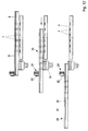
- FIG. 1 schematically shows the essential elements of a device 1, with which break-sensitive tablets 2 are finally deposited in yards 3 of a deep-drawn bottom foil 4.
- the tablets 2 pass from a tablet press, not shown, or a supply according to arrow 5 randomly on a tilted slide 6.
- the chute 6 can also be designed as a vibratory conveyor and serve to deliver the tablets 2 targeted in time.
- a part of the bottom of the chute 6 or the entire chute 6 may be formed as a sieve bottom and provided with holes 7 ( Figure 4).
- the diameter of the holes 7 is smaller than the diameter of the tablets 2, so that at this point only those pieces 8 of tablets 2 fall through whose effective dimensions are smaller than the diameter of a tablet 2. It is understood that in addition to the pieces 8 and dust from the material of the tablets is discharged through the holes 7.
- a Aufrichtstation 9 by means of which the tablets are erected.
- the Aufrichtstation thus serves to rotate the lying on the slide 6 lying flat tablets, so to transfer to a rotated position, wherein the axis of the disc-shaped body of the tablet is either completely or at least partially aligned horizontally.
- the tablets are thereby completely set up, so that they ultimately stand up on the edge of the tablet and form successively into tablet strands in which the tablets 2 are strung together in a strand, as can be seen from FIG is. In this way, a plurality of side by side and each separately guided tablet strands 10 are generated, it does not depend on the number of tablets.
- one or more sensors 11 are arranged, which detect the degree of filling of Aufrichtstation 10 and with the signals of the production speed of the tablet press can be changed.
- the aim of such a control is to always have enough tablets in the erection station 9. It is understood that not all tablets 2 in the Friedrichtstation are undamaged. Among them, on the contrary, there are also damaged tablets which could not be removed through the holes 7 in the chute 6. It can already be seen that the tablets 2 are moved substantially rolling in the erected position, ie under very low stress, whereby the risk of breakage of fragile tablets is considerably reduced.
- the erection station 9 is designed to be permeable downwards, so that smaller fragments and dust can be removed from tablets according to arrow 12 here as well.
- the arrangement of a suction device below the erection station 9 is possible.
- the erection station 9 has lamellae 13, 14, which form gaps and passages between them. The training in detail will be explained later.
- the slats 13 and 14 extend substantially inclined downwards and over the length of the erecting station 9.
- the slats 13 and 14 have vertically projecting extensions 15, which protrude upwards. The spaces between the extensions 15 are closed in the projecting area, so that here a weir for damming the tablets 2 is formed in the flow.
- passages 16 are provided, which are dimensioned slightly higher than the diameter of a tablet and slightly wider than the thickness of the tablet, so that at this point, at which the passage adjoins a gap, only one tablet can pass through each.
- the tablets 2 are arranged in or to the tablet strands 10.
- control station 17 At the erection station 9 is followed in the flow of the tablets 2, a control station 17 at.
- the control station 17 has a driven in the direction of arrow 18 endless belt 19, which is formed for example as a cam belt and receiving places for Tablets provides 2, in which the tablets at a distance, so isolated and released taken.
- endless belt 19 which is formed for example as a cam belt and receiving places for Tablets provides 2, in which the tablets at a distance, so isolated and released taken.
- the control station 17 is adjoined by a storage and dispensing station 20, which essentially consists of a plurality of adjacent curved and downwardly guided channels, in which the tablets 2 in turn are piled up into tablets strands 10, ie lying against one another.
- the channels can also be designed to be slightly divergent under spreading action. While the tablets 2 are isolated in the control station 17 in order to easily check for damage and z. For example, to dislodge a damaged tablet 21, only proper undamaged tablets in the jam and dispensing station 20 are dammed up into tablet strands 10.
- the storage and discharge station has at the end a slider 22 which is movable in two positions. In one position, he closes the storage and delivery station, so that no tablets 2 are delivered. In the other position he opens the storage and discharge station, so that tablets 2 can be delivered in a controlled manner.
- the storage and discharge station 20 has a plurality of mutually separate and juxtaposed webs 23, in which the individual tablet strands are formed or reduced.
- the transfer unit 24 serves to receive the tablets 2 in the erected state corresponding to the pitch of the courtyards 3 of the bottom foil 4 and for transferring the tablets on the courtyards 3 and for turning back the tablets 2 immediately before their release from the erected position in the flat position, the the tablets 2 in the courts 3 ultimately have to take.
- the transfer unit 24 has two mutually superposed, substantially horizontally extending plates 25 and 26, which are jointly according to arrow 29 on the bottom foil 4 grid-accurate to the farms 3 can be transferred.
- the upper plate 25 has recesses 27.
- the recesses 27 have a rectangular cross section corresponding to the diameter and the thickness of the tablets 2.
- the recesses 27 extend in a vertical direction through the upper plate 25 therethrough.
- inclined or arcuate channels 28 are provided in the lower plate 26.
- the plates 25 and 26 are not only movable together according to arrow 29, but also relative to each other at least in two positions can be transferred. In one position, the recesses 27 of the upper plate 25 through the lower plate 26th closed, while in the other position, the channels 28 to the recesses 27 have connection. This training will be explained in detail later in more detail.
- the transfer station 24 and the two plates 25 and 26, a device 30 for sucking dust and small fragments of tablets from the recesses 27 and the subsequent channels 28 is provided.
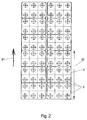
- the bottom foil 4 which is moved clockwise in accordance with arrow 31, has the yards 3 in the corresponding grid dimension.
- six courtyards 3 are arranged in a row, so that the upper plate 25 of the transfer unit 24 has six such recesses 27 at the appropriate distance.
- 32 36 courtyards 3 are provided with a trigger, which must be filled with tablets 2.
- the upper plate 25 has 36 recesses arranged in the illustrated pitch.
- the storage and discharge station 20 has six tracks 23 which are arranged side by side.
- any other grid can be used in principle. For this purpose, individual elements and stations must be formed as a format parts and replaced accordingly.
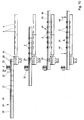
- Fig. 3 illustrates once again the relative arrangement of the tracks 23 of the storage and discharge station 20 for an embodiment in which a trigger 32 does not go over six but over twelve rows.
- the top plate 25 has 72 recesses 27 which are filled upright with tablets 2.
- the Aufrichtstation 9 are arranged in twelve-fold copy and the control station 17 twelve times next to each other, although they are here for the sake of clarity only indicated in each case simply.
- Fig. 3 illustrates that the device can be created or adapted in any desired pitch.
- Fig. 4 shows a plan view of the elements between the tablet press and the erection station 9.
- the tablet press may have an outlet 33, which is moved to distribute the tablets to be dispensed according to double arrow 34 transversely to the working direction and forth.
- vanes 35 or similar vanes may be arranged to cause the flow of the dispensed tablets 2 (not shown) to more or less limit the working width of the chute 6 bounded by side walls 36 equally distributed.
- the subsequent Holes 7 allow dust and broken pieces of the tablets to fall downwards, so that only damage-free tablets and tablets which have only a relatively small damage run into the erection station 9.
- the flow of tablets is combined via baffles 37 and distributed to the region of the fins 13 and 14.
- the tablets 2 (not shown) are still in a flat lying disorderly position, where they can also be tilted against each other and also come to rest on top of each other. Between adjacent lamellae 13 and 14 column 38 are formed, so here twelve columns according to the embodiment of Fig. 3. It can be provided sensors 11 to control the wings 35 and to ensure that at all points on the working width of the slats 13, 14 a sufficient number of tablets is present.
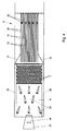
- FIG. 5 again illustrates this area already shown in FIG. 4, the number of lamellae 13 and 14 being changed for reasons of clarity.
- the area of Aufrichtstation 9 only a few tablets are shown, wherein the flow of tablets is generally larger and more dense. It is indicated that the fins 14 are in their lower position, while the fins 13 are just raised. Thus, there is the opportunity for the tablets 2 to slip laterally into the gap 38 formed between the slats 13 and 14 and thus to move from the flat position to the raised position by 90 °. Some of the erected tablets 2 are recognizable.
- Below the column 38 is a continuous bottom 39, on which the tablets 2 are deposited with their edges rising, moving in the columns 38 rolling forward.
- gate-like passages 16 are formed in the region of the projections 15, through which only one tablet in each case can roll through in a track or a gap 38, wherein the tablets 2 form during and after passage into tablets strands 10.
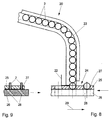
- Fig. 6 illustrates once again the erection process of the tablets 2 in the erection station 9.
- the slide 6 shown with their holes 7, by means of which the tablets 2 are brought in disorderly relative position. In this position they reach the Aufrichtstation 9 with the vertically movable according to the arrows 40 slats 13 and 14.
- the slats 13 and 14 can be mounted vertically movable and arranged against each other. It only depends on supporting points for inclined planes form, where the tablets 2 can slip into the column 38, wherein they sit up and as shown in Fig. 6, stand up on its edge or rolling on this can move forward. It is understood that in this way all the gaps 38 are filled with upright oriented tablets 2.
- the bottom 39 may be formed as a sieve bottom. At him, the standing tablets 2 are each based. Dust and smaller debris can fall through the bottom 39 and / or be sucked out. It is also possible, for. B. to arrange the slats 14 stationary and only the slats 13 to move up and down.
- the lamellae 13 can be pivoted on a common lamellar axis and be moved by means of a crank drive or a cam drive with a vertical movement component, so that the erection of the tablets 2 takes place.
- Fig. 7 shows the structure and operation of the control station illustrated 17.
- the endless circulating belt 19 inclined and form, so that the tablets 2 can be accommodated not only with its edge, but also with its one end lying, the axis of the tablet 2 is no longer horizontal, but inclined ,
- This relative position makes it possible to arrange optical systems with a plurality of cameras 41 in a small space next to one another, as required according to the tablet strands 10 running side by side. A damaged in the edge region tablet 21 is detected by the camera 41 and discharged, while undamaged tablets 2 are transferred to the storage and discharge station 20.
- the discharge of a damaged tablet can be carried out by means of an air flow through a nozzle 42 through an indicated opening in the band 19 therethrough.
- a suction device according to the arrows 43 can be used. It is understood that the discharge of a damaged tablet 21 is controlled by the signals of the respective camera 41.
- the tablets 2 and 21 are received lying inclined on the belt 19 to allow a scale-like coverage with the plurality of cameras 41 in a small space. At the transition of the tablets into the stowage and dispensing station 20, in turn, the rotation can be achieved in the fully erected position.
- Fig. 8 illustrates the congestion and discharge station 20, in which case only one path 23 with the pent-up tablets 2 is indicated.
- the walls of the web 23 terminate at different heights relative to the transfer unit 24, wherein from the bottom of the recesses 27 to a side wall, a free space is created, which is dimensioned slightly larger than the diameter of a tablet.
- the slider 22 is in its open position.
- the recesses 27 are closed on the bottom side by the lower plate 26.
- the transfer unit 24 is moved in accordance with arrow 29 under the storage and discharge station 20, wherein in each case at the lower end of the storage and discharge station 20 each a tablet penetrates into a recess 27 and is deposited there standing. It is understood that this is done simultaneously at several tracks 23 of the storage and dispensing station 20, so that fill all the wells 27 on the transfer unit 24 and the number of tablets are deposited according to the intended and to be filled at once pitch of the courtyards.
- Fig. 9 shows a cross section of a rotated by 90 ° viewing direction with reference to a section. It can also be seen that the recesses 27 are closed by the relative position of the plates 25 and 26 on the bottom side, so that the channels 28 have no connection to the recesses 27. In this position, the plates 25 and 26 of the transfer unit 24 are brought together according to arrow 29 on the bottom foil 4, wherein the outlets of the channels 28 in relation to the farms 3 arrive. By a relative movement of the plates 25 and 26, the recesses get 27 connection to the channels 28, so that the tablets are stored according to the grid simultaneously in the courtyards, the tablets are rotated back from the erected position in the flat position.
- the transfer unit 24 In the starting position shown in Fig. 10 above, the transfer unit 24 is located below the storage and discharge station 20. The sliders 22 are open. The two plates 25 and 26 are in such a relative position to each other, in which the recesses 27 are closed on the bottom side. From this position, the transfer unit 24 passes under the outlets of the storage and discharge station 20, wherein the tablets 2 are deposited one by one in one of the recesses 27 successively until the field of the recesses 27 is completely filled with upright tablets, as shown in second illustration of FIG. 10 can be seen. The slides 22 are transferred to the closed position, so that the tablets 2 are prevented from further leakage.
- the transfer unit 24 reaches its grid-exact position above the courtyards 3 in the bottom sheet 4.
- the transfer unit 24 is lowered according to the arrows 44 in order to reduce the drop height.
- Fig. 11 illustrates the relative position of the parts in this step again in a cross section in a direction of rotation rotated by 90 °.
- the recesses 27 are still closed at the bottom, so that the tablets 2 are in the rotated standing position.
- the lower plate 26 is displaced in the direction of the arrow 45 so that the channels 28 are aligned with the recesses 27.
- the tablets 2 slide gently and with a low drop height in the courtyards 3 of the bottom foil. 4
- the transfer unit is first raised according to the further step shown in Fig. 12 above.
- the lowering according to the arrows 44 and the increase in the opposite direction can be configured adjustable.
- the bottom foil 4 is moved further by a further trigger, so that a grid of unfilled yards 3 is brought forward.
- the device 30 comes into operation to suck dust from the recesses 27 and the subsequent channels 28 and thus to clean the transfer unit 24.
- the plates 25 and 26 are again moved relative to each other so that the recesses 27 are closed on the bottom side. This is followed by the following cycle.
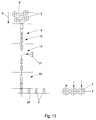
- FIG. 13 once again illustrates the individual steps with which the tablets 2 are treated and finally deposited in the yards.
- the tablets 2 are initially in a disorderly flat-lying state in the region of the chute 6, which they occupy after exiting a tablet press 5.
- the tablets are erected upright and formed into tablets strands 10.
- the tablets 2 are in isolated state and are individually controlled, the tablets 2 either standing or obliquely going through the control station 17. Damaged tablets 21 are discharged.
- the subsequent storage and dispensing station 20 are the checked undamaged tablets 2 in turn dammed, taking their erect position still. This is also the case in the area of the subsequent transfer unit 24.
- the tablets 2 are arranged in the recesses of the transfer unit 24 according to the predetermined pitch of the bottom foil. Finally, the tablets 2 are deposited in the courtyards 3 of the bottom film, where they are turned back into the flat state.
- the transfer unit 24 is designed here as a metering roller 46, which carries the recesses 27 on its circumference.
- the depressions 27 are connected to a vacuum source, so that they are carried along the continuous drive of the metering roller 46 as indicated by arrow 47 over half of the circumference of the metering roller 46 and accurately in the courtyards 3 of the bottom foil 4.
- the dispensing can take place directly or by means of a channel (not shown) which assists the return rotation into the flat position. It is understood that here the tablets 2 are always stored in rows.
- the drive of the metering roller 46 and the deduction of the bottom film 4 are carried out continuously here.
Abstract
Description
Die Erfindung betrifft ein Verfahren zum Einlegen von Tabletten in die Höfe tiefgezogener Bodenfolie, indem die aus einer Tablettenpresse oder einem Vorrat flachliegend auslaufenden Tabletten aufgestaut und zu Tablettensträngen geordnet werden, worauf die Tabletten der Tablettenstränge einzeln in je einen Hof in der Bodenfolie abgelegt werden, wobei Stücke und Staub beschädigter Tabletten entfernt werden. Die Erfindung zeigt und beschreibt auch eine Vorrichtung zum Einlegen von aus einer Tablettenpresse oder einem Vorrat flachliegend auslaufenden Tabletten in die Höfe tiefgezogener Bodenfolie, mit einem Staubildner, einem Strangbildner und einer Überführeinheit zum vereinzelten Ablegen der Tabletten in je einen Hof in der Bodenfolie, wobei Stücke und Staub beschädigter Tabletten entfernt werden. Bei den von der Erfindung angesprochenen Tabletten handelt es sich um scheibenförmige Körper, die im Wesentlichen einen zylindermantelförmig verlaufenden Rand und zwei Kreisflächen aufweisen, die eben oder auch konkav oder konvex geformt verlaufen können. Die Tabletten können aus dem Gebiet der Pharmazie, aber auch aus dem Gebiet der Bonbonherstellung stammen. In allen Fällen handelt es sich um scheibenförmige Körper mit einem Verhältnis von Durchmesser zu Dicke etwa im Bereich von 3:1. Damit werden insbesondere relativ dünne Tabletten angesprochen, die zudem nicht sehr verdichtet gepresst sind, so dass sie während der Behandlung bis zur Verpackung einer erheblichen Bruchgefahr unterliegen. Solche Tabletten sind beispielsweise als Brausetabletten bekannt, bei denen zwischen der Tablettenpresse und der Verpackung nicht nur die Bruchgefahr in Form von Stücken auftritt, sondern durch Reibung und Handhabung auch eine relativ große Menge an Staub entsteht, der ähnlich oder zusätzlich zu den Stücken zu einer Verstopfungsgefahr und damit zu Betriebsunterbrechungen verbunden mit Reinigungsvorgängen führen kann.The invention relates to a method for inserting tablets into the courtyards of deep-drawn bottom sheet by damming out of a tablet press or a supply expiring lying tablets and ordered into tablets strands, whereupon the tablets of the tablet strands are individually stored in a yard in the bottom sheet, said Pieces and dust of damaged tablets are removed. The invention also shows and describes a device for inserting from a tablet press or a supply flat leaking tablets in the court deep-drawn bottom sheet, with a Staubildner, a strand former and a transfer unit for scattering the tablets in a separate yard in the bottom sheet, with pieces and remove dust from damaged tablets. The tablets addressed by the invention are disk-shaped bodies which essentially have a rim extending in the shape of a cylinder jacket and two circular surfaces which can run flat or else concave or convex. The tablets can come from the field of pharmacy, but also from the field of candy production. In all cases, they are disc-shaped bodies with a diameter-to-thickness ratio in the range of 3: 1. This is particularly addressed relatively thin tablets, which are also not pressed very compact, so that they are subject to a considerable risk of breakage during treatment to the packaging. Such tablets are known, for example, as effervescent tablets, in which not only the risk of breakage in the form of pieces occurs between the tablet press and the packaging, but also a relatively large amount of dust is produced by friction and handling, which, similarly or in addition to the pieces, creates a risk of clogging and thus can lead to business interruptions associated with cleaning operations.
Ein Verfahren und eine Vorrichtung der eingangs beschriebenen Art sind aus der US 6,311,462 B2 bekannt. Die Tabletten werden in einer Tablettenpresse in schneller Folge gepresst und gelangen in großen Stückzahlen auf eine abwärts geneigte Rutsche. Anschließend werden die Tabletten flachliegend von einem Förderband aufgenommen, über dem besonders gestaltete Seitenwände angeordnet sind, um die Tabletten aufzustauen. Das Aufstauen dient gleichzeitig der Verteilung der Tabletten quer zur Arbeitsrichtung vor einem Strangbildner, in dem die Tabletten zu Tablettensträngen angeordnet werden, so dass die Tabletten jeweils hintereinander in einem Strang formiert werden, und sich zwei benachbarte flachliegende Tabletten jeweils nur an einer Stelle randseitig berühren. Zu diesem Zweck weist der Strangbildner Kanäle auf, in denen die Tablettenstränge aufgestaut werden. Der Auslauf des Strangbildners ist mit einer Anschlagleiste verschlossen, so dass das Aufstauen der Tabletten im Strangbildner erfolgt. Es ist eine Überführeinheit vorgesehen, die mit Saugern bestückt ist. Die Überführeinheit wird über die Tablettenstränge im Strangbildner abgesenkt, so dass die vordersten Tabletten, die von der Anschlagleiste zurückgehalten werden, durch Saugen flachliegend aufgenommen und in Richtung auf die Bodenfolie bewegt und einzeln in je einen Hof in der Bodenfolie abgelegt werden. Die Sauger der Überführeinheit ergreifen dabei auch beschädigte Tabletten, wenn diese noch relativ groß sind. Kleinere Tablettenstücke können dagegen nicht aufgenommen werden, so dass letztendlich neben unbeschädigten Tabletten auch beschädigte Tabletten in die Höfe in der Bodenfolie eingelegt werden, als auch Fehlstellen in der Verpackung entstehen, in denen sich keinerlei Tabletten befinden. Die Anschlagleiste ist anhebbar gestaltet, so dass sich im Strangbildner ablagernder Staub und kleine abgebrochene Tablettenstücke ausgeschleust werden können. Sobald neue Tabletten im Strangbildner nachgerückt sind, muss die Anschlagleiste wieder in ihre Wirkstellung verbracht werden. Es ist vorgesehen, die Anschlagleiste auch manuell öffnen zu können, um auf diese Weise Tablettenstücke und unbeschädigte Tabletten für einen steuerbaren Zeitraum gemeinsam als Abfall auszuschleusen und damit Bereiche des Strangbildners zu reinigen. Es versteht sich, dass die einzelnen Stationen in ihrer Arbeitsgeschwindigkeit so aufeinander abgestimmt werden müssen, dass möglichst keine Fehlstellen entstehen.A method and a device of the type described above are known from US 6,311,462 B2. The tablets are pressed in rapid succession in a tablet press and arrive in large numbers on a downwardly inclined chute. Subsequently, the tablets are received lying flat by a conveyor belt, over which specially designed side walls are arranged to accumulate the tablets. The damming also serves to distribute the tablets transversely to the working direction in front of a strand former, in which the tablets are arranged in tablet strands, so that the tablets are each formed one behind the other in a strand, and touching two adjacent flat-lying tablets at one edge edge. For this purpose, the strand former on channels in which the tablets strands are dammed. The outlet of the strand former is closed with a stop bar, so that the damming of the tablets takes place in the strand former. It is provided a transfer unit, which is equipped with suckers. The transfer unit is lowered over the tablet strands in the strand former, so that the foremost tablets, which are retained by the stop bar, taken up by sucking lying flat and moved towards the bottom sheet and individually stored in a respective yard in the bottom sheet. The suckers of the transfer unit also take damaged tablets if they are still relatively large. Smaller pieces of tablets, on the other hand, can not be absorbed, so that in addition to undamaged tablets and damaged tablets are inserted into the courtyards in the bottom film, as well as defects in the packaging arise in which there are no tablets. The stop bar is designed liftable, so that in the strand former depositing dust and small broken tablet pieces can be discharged. As soon as new tablets are added in the strand former, the stop bar must be returned to its operative position. It is envisaged to be able to open the stop bar manually, in order to eject in this way tablet pieces and undamaged tablets for a controllable period together as waste and thus to clean areas of the strand former. It goes without saying that the individual stations must be coordinated with one another in terms of their working speed in such a way that as far as possible no defects occur.
Nachteilig an dem bekannten Verfahren und der Vorrichtung ist es, dass die Beanspruchung der Tabletten zwischen der Tablettenpresse und ihrer Überführung in die Höfe der Bodenfolie relativ hoch ist, so dass auch der Bruch- und Staubanteil insbesondere bei wenig fest gepressten Tabletten entsprechend hoch ist. Durch Bruch und Staub ergeben sich Betriebsstörungen einerseits, die wieder behoben werden müssen, und andererseits Fehlpackungen mit Höfen, die angebrochene Tabletten und/oder Fehlstellen enthalten. Diese Arbeitsweise lässt sich nicht vermeiden, obwohl an verschiedenen Stellen Absaugeinrichtungen vorgesehen sind, um Tablettenstaub und kleinere abgebrochene Tablettenstücke abzusaugen.A disadvantage of the known method and the device is that the stress on the tablets between the tablet press and its transfer into the courtyards of the bottom foil is relatively high, so that even the fraction and dust content, especially at little fixed pressed tablets is correspondingly high. Breakage and dust can lead to malfunctions, which must be repaired, as well as incorrect packaging with farms that contain open tablets and / or defects. This operation can not be avoided, although at various points suction devices are provided to suck off tablet dust and smaller broken tablet pieces.
Der Erfindung liegt die Aufgabe zugrunde, ein Verfahren und eine Vorrichtung zum Einlegen von Tabletten in die Höfe tiefgezogener Bodenfolie aufzuzeigen, bei der die Tabletten schonender behandelt werden, so dass die Bruchgefahr reduziert ist. Nicht beschädigte Tabletten sollen in die tiefgezogenen Höfe einer Bodenfolie mit erhöhter Betriebssicherheit eingelegt werden.The invention has for its object to provide a method and apparatus for inserting tablets in the courtyards of deep-drawn bottom sheet, in which the tablets are treated gently, so that the risk of breakage is reduced. Non-damaged tablets should be placed in the deep-drawn courts of a bottom foil with increased operational safety.
Die Aufgabe der Erfindung wird erfindungsgemäß mit den Merkmalen der unabhängigen Patentansprüche 1 und 5 gelöst.The object of the invention is achieved according to the invention with the features of the
Die Erfindung geht von dem Gedanken aus, die flachliegend ankommenden Tabletten in eine gedrehte Stellung aufzurichten, um sie in der aufgerichteten Stellung handhaben zu können. Diese gedrehte Stellung wird über weite Bereiche des Verfahrens aufrechterhalten. Erst im letzten Moment vor dem flachliegenden Ablegen der Tabletten in die Höfe der tiefgezogenen Bodenfolie erfolgt die Rückdrehung in die flachliegende Stellung. Unter der flachliegenden Stellung wird eine Stellung verstanden, bei der die Achse einer Tablette senkrecht oder zumindest etwa senkrecht angeordnet ist, wie dies beispielsweise auf einer geneigt verlaufenden Rutsche der Fall ist. Unter einer gedrehten Stellung wird eine Stellung verstanden, in der die Achse der Tablette waagerecht oder zumindest etwa waagerecht mit kleinem Neigungswinkel verläuft. Im einen Fall wird die Tablette mit waagerecht ausgerichteter Achse auf ihrem Rand aufgestellt. Im anderen Fall, also bei leicht geneigter Stellung, ergeben sich an der Tablette Kräfte, die teilweise am Rand, teilweise an einer der beiden Stirnflächen angreifen. Im letzteren Fall wird eine Kräfteaufteilung und damit auch eine Aufteilung der Beanspruchung der Tablette während ihrer Handhabung erreicht, wodurch die Bruchgefahr reduziert wird. Da die Tabletten einen kreisbogenförmig verlaufenden Rand besitzen, ergibt sich die Möglichkeit, die Tabletten in der aufgerichteten Stellung auf dem Rand rollend weiterzubewegen, wobei also die bei flachliegender Behandlung auftretende Gleitreibung durch eine Rollreibung ersetzt wird, die die Tablette vergleichsweise weniger beansprucht. Zur Aufnahme von Kräften erscheint der Rand einer Tablette besser geeignet als die beiden Stirnflächen der Tablette. Durch die Behandlung der Tabletten in der gedrehten Stellung ist die Bruchgefahr wesentlich reduziert. Diese Erkenntnis überrascht, weil ja Tabletten in einer Tablettenpresse senkrecht zu ihrer Haupterstreckungsebene gepresst werden.The invention is based on the idea to erect the flat-lying incoming tablets in a rotated position in order to handle them in the erected position can. This rotated position is maintained over wide areas of the process. Only at the last moment before laying flat of the tablets in the courtyards of the deep-drawn bottom sheet, the reverse rotation takes place in the flat position. The flat lying position is understood to mean a position in which the axis of a tablet is arranged perpendicularly or at least approximately vertically, as is the case, for example, on a sloping chute. Under a rotated position is understood a position in which the axis of the tablet is horizontal or at least approximately horizontally with a small angle of inclination. In one case, the tablet is set up with a horizontal axis on its edge. In the other case, that is to say in the case of a slightly inclined position, forces arise on the tablet which partly act on the edge, partly on one of the two end faces. In the latter case, a division of forces and thus also achieves a distribution of the stress on the tablet during its handling, whereby the risk of breakage is reduced. Since the tablets have an arcuate edge, there is the possibility of moving the tablets in the erect position on the edge rolling, so that the sliding friction occurring in flat lying treatment is replaced by a rolling friction that comparatively less stress on the tablet. To absorb forces, the edge of a tablet appears more suitable than the two end faces of the tablet. By treating the tablets in the rotated position, the risk of breakage is significantly reduced. This finding is surprising because tablets are pressed in a tablet press perpendicular to their main extension plane.
Wenn die Tabletten aus der flachliegenden Stellung um etwa 90° in die gedrehte Stellung aufgerichtet werden, stehen sie auf ihrem Rand auf, so dass die Rollreibung während ihres Transportes voll genutzt werden kann und allenfalls geringfügige Gleitreibungskräfte auf die Stirnseiten der Tabletten einwirken, die von Führungselementen, Leitstegen oder dergleichen herrühren. Es ist aber auch möglich, die Tabletten aus der flachliegenden Stellung um beispielsweise etwa 45° bis 60° in die gedrehte Stellung zu drehen und so eine Kraftaufteilung herbeizuführen. All diese gedrehten Stellungen sind bestens geeignet, die Tabletten schonend zu behandeln. Insbesondere besteht die Möglichkeit, die Tabletten in ihrer gedrehten Stellung in sehr einfacher Weise zu vereinzeln, um sie dann einzeln auf Beschädigungen überprüfen zu können.When the tablets are raised from the flat position by about 90 ° in the rotated position, they stand on its edge, so that the rolling friction can be fully utilized during their transport and at most slight sliding friction forces act on the end faces of the tablets, of guide elements , Leitstegen or the like. But it is also possible to rotate the tablets from the flat position by, for example, about 45 ° to 60 ° in the rotated position and thus bring about a force distribution. All these rotated positions are best suited to treat the tablets gently. In particular, there is the possibility of separating the tablets in their rotated position in a very simple manner in order to be able to individually check them for damage.
So werden die aufgerichteten Tabletten der Tablettenstränge vereinzelt und in der vereinzelten Stellung auf Beschädigungen überprüft. Beschädigte Tabletten werden einzeln ausgeschleust, so dass dem weiteren Verfahren nur unbeschädigte Tabletten zugrunde gelegt werden. Die Gefahr, dass solche unbeschädigten Tabletten bei weiteren Verfahrensschritten beschädigt werden, ist relativ gering. Zum einen schließen sich nur relativ wenige Verfahrensschritte an und die Tabletten wurden in vorausgehenden Verfahrensschritten vergleichsweise stärker belastet, so dass sie, wenn eine Bruchempfindlichkeit vorgelegen hätte, bereits vor der Überprüfung gebrochen sein müssten.Thus, the erect tablets of the tablet strands are isolated and checked in the isolated position for damage. Damaged tablets are discharged individually, so that the further procedure is based on undamaged tablets only. The risk that such undamaged tablets are damaged in further process steps, is relatively low. On the one hand, only a relatively small number of process steps follow and the tablets were comparatively more heavily loaded in previous process steps, so that if there had been a sensitivity to breakage, they would have had to be broken before the test.
Die unbeschädigten überprüften Tabletten der Tablettenstränge werden aus der vereinzelten Stellung heraus wiederum mit Überschuss aufgestaut, d. h. an der Staustelle liegt eine größere Anzahl von Tablettensträngen vor, als einer Reihe von Höfen gemäß dem Rastermaß der Bodenfolie entsprechen. Bei diesem Aufstauen können die Tablettenstränge auch gespreizt werden, d. h. der gegenseitige Abstand der Tablettenstränge kann entsprechend dem Rastermaß der Höfe festgelegt werden. Die Tabletten werden vereinzelt in gedrehter Stellung in Vertiefungen einer plattenförmigen Überführeinheit abgestellt, wobei sie randseitig auf einem Boden stehend aufruhen. Das Zurückdrehen der Tabletten in die flachliegende Stellung erfolgt erst während ihres Durchtrittes durch die Überführungseinheit und damit unmittelbar vor dem Ablegen in die Höfe. Umgekehrt erfolgt das Aufrichten der Tabletten aus der flachliegenden in die gedrehte Stellung möglichst frühzeitig im Verfahren, also unmittelbar nach dem Auslaufen der Tabletten aus einer Tablettenpresse oder aus einem Vorrat. Die wesentlichen Verfahrensschritte erfolgen in der aufgerichteten Stellung der Tabletten.The undamaged tablets of the tablet strands are again dammed with excess from the isolated position, ie there is a larger number of tablet strands at the jam site than a number of pens according to the grid dimension correspond to the bottom foil. In this damming the tablet strands can also be spread, ie the mutual distance of the tablet strands can be determined according to the pitch of the courtyards. The tablets are occasionally placed in the rotated position in depressions of a plate-shaped transfer unit, wherein they rest on the edge standing on a floor. The turning back of the tablets in the flat position takes place only during their passage through the transfer unit and thus immediately before taking them into the yard. Conversely, the raising of the tablets from the flat to the rotated position takes place as early as possible in the process, ie immediately after the tablets have run out of a tablet press or from a supply. The essential process steps take place in the erected position of the tablets.
Die Vorrichtung zum Einlegen von aus einer Tablettenpresse oder einem Vorrat flachliegend auslaufender Tabletten in Höfe tiefgezogener Bodenfolie erfolgt mit einem Staubildner, einem Strangbildner und einer Überführeinheit zum vereinzelten Ablegen der Tabletten in je einen Hof in der Bodenfolie. Stücke und Staub beschädigter Tabletten werden an den verschiedenen Stellen der Vorrichtung entfernt, insbesondere abgesaugt, wo dies sinnvoll und erforderlich ist.The device for inserting from a tablet press or a store lying flat expiring tablets in court deep-drawn bottom sheet is done with a Staubildner, a strand former and a transfer unit for scattering the tablets in each case a yard in the bottom sheet. Pieces and dust of damaged tablets are removed at the various points of the device, in particular aspirated, where appropriate and necessary.
Wesentliches Element der Vorrichtung ist eine Aufrichtstation, mit der die Tabletten aus der flachliegenden Stellung in eine gedrehte Stellung aufgerichtet werden, in der sie zumindest teilweise, vorzugsweise aber gänzlich auf ihrem Rand aufstehen. In der Bearbeitungsfolge schließen sich dann weitere Stationen zur Behandlung der Tabletten in der gedrehten aufgerichteten Stellung an. Schließlich ist eine Überführeinheit vorgesehen, die dazu dient, die Tabletten in die flachliegende Stellung zurückzudrehen. Diese Überführeinheit weist geneigt oder bogenförmig verlaufende Kanäle auf, durch die die Tabletten rutschen und dabei zurückgedreht, also in die flachliegende Stellung zurückgeführt werden.An essential element of the device is a Aufrichtstation with which the tablets are erected from the flat position in a rotated position in which they stand up at least partially, but preferably completely on its edge. The processing sequence is followed by further stations to treat the tablets in the rotated upright position. Finally, a transfer unit is provided which serves to turn the tablets back into the flat position. This transfer unit has inclined or arcuate channels through which the tablets slip and thereby turned back, so are returned to the flat position.
Die Aufrichtstation kann eine Vielzahl sich im Wesentlichen vertikal erstreckende und in vertikaler Richtung beweglich angetriebene Lamellen aufweisen, zwischen denen der Dicke der Tabletten entsprechende Spalte gebildet sind. Die Spalte sind bodenseitig geschlossen ausgebildet, was durch eingestellte Bleche, aber auch durch einen über die Arbeitsbreite durchgehenden Boden realisiert werden kann. Die Aufrichtstation weist der Dicke und dem Durchmesser der Tabletten entsprechende Durchlässe auf, wobei die Dimensionen so gewählt sind, dass jeweils eine Tablette durch einen Durchlass hindurchrollen kann, jedoch verhindert wird, dass mehrere Tabletten gleichzeitig hindurch treten oder sich verkeilen können. Die Lamellen sind mit ihren Arbeitsebenen schräg angeordnet, so dass die aufgestauten Tabletten in die aufgerichtete Stellung überführt, also gedreht werden. Die Lamellen können in Form von zwei Lamellenpaketen vorgesehen sein, wobei das eine Lamellenpaket ortsfest und das andere Lamellenpaket dazu relativbeweglich angeordnet sein kann. Auf diese Weise werden immer wieder geneigte Flächen geschaffen, an denen die Tabletten zwischen Lamellen in Spalte einrutschen können, wobei sie gedreht und dabei aufgerichtet werden. Es ist aber auch möglich, beide Lamellenpakete relativ zueinander zu bewegen oder auf die Ausbildung von gleichförmig bewegten Lamellen zu verzichten und stattdessen die Lamellen in einer Folge quer über die Arbeitsbreite zu bewegen. Die Lamellen können in einer gemeinsamen Achse schwenkbar aufgehängt sein. Für die Bewegung der Lamellen mit einer vertikalen Bewegungskomponente gibt es wieder eine ganze Reihe von Möglichkeiten. Hier lässt sich ein Kurbeltrieb oder ein Nockentrieb sinnvoll einsetzen. Die Aufrichtstation kann auch mit einem Vibrationsantrieb versehen sein, der die Auf- und Abbewegung der Lamellen überlagert. Die Aufrichtstation kann gleichzeitig als Aufstaustation ausgebildet sein. Sie ist in der Regel unmittelbar nach dem Auslauf einer Tablettenpresse angeordnet, damit die wesentliche Behandlung der Tabletten in aufgerichtetem Zustand nachfolgen kann.The erecting station may comprise a plurality of substantially vertically extending and vertically movably driven lamellae, between which the thickness of the tablets corresponding gaps are formed. The gaps are formed closed on the bottom side, which can be realized by discontinued sheets, but also by a continuous through the working width bottom. The Aufrichtstation has the thickness and the diameter of the tablets corresponding passages, the dimensions so are chosen so that each one tablet can roll through a passage, but prevents multiple tablets can pass through or wedge at the same time. The slats are arranged obliquely with their working levels, so that the pent-up tablets transferred to the upright position, ie rotated. The slats can be provided in the form of two disk packs, one of the disk packs fixed and the other disk pack can be arranged to be relatively movable. In this way, again and again inclined surfaces are created, where the tablets can slip between fins in column, being rotated and thereby erected. But it is also possible to move both disk sets relative to each other or to dispense with the formation of uniformly moving blades and instead to move the blades in a row across the working width. The slats can be suspended pivotally in a common axis. For the movement of the slats with a vertical component of motion there are again a whole series of possibilities. Here, a crank drive or a cam drive can be used wisely. The erection station may also be provided with a vibration drive superimposed on the up and down movement of the slats. The Aufrichtstation can be formed simultaneously as Aufstaustation. It is usually arranged immediately after the outlet of a tablet press, so that the essential treatment of the tablets can follow in the erected state.
Bei einer besonders sinnvollen Ausführungsform weist die Überführeinheit zwei aufeinander liegende, sich im Wesentlichen horizontal erstreckende Platten auf, die einerseits gemeinsam gesteuert bewegbar sind, insbesondere um sie aus einer Beladestellung in eine Ablegestellung oberhalb der Bodenfolie zu versetzen. Andererseits sind die beiden aufeinander liegenden Platten gesteuert relativ zueinander verschiebbar. Die obere Platte weist vertikal durchgehende Vertiefungen zum Abstellen der Platten auf. Die Vertiefungen besitzen vorzugsweise rechteckigen Querschnitt entsprechend dem Durchmesser und der Dicke einer Tablette, wobei freilich immer das erforderliche Spiel für die Bewegung der Tablette vorgesehen ist. Die beiden Platten können so gegeneinander positioniert werden, dass die untere Platte die durchgehenden Vertiefungen in der oberen Platte nach unten abschließt. In dieser Stellung erfolgt das Aufstellen der Tabletten in die Vertiefung hinein. Die Vertiefungen sind vorzugsweise bereits im Rastermaß der Höfe der Bodenfolie angeordnet, so dass ein Spreizen der Tabletten während der Überführung nicht mehr erforderlich ist. Die untere Platte weist geneigt oder bogenförmig verlaufende Kanäle auf, durch die die Tabletten mit Spiel durchrutschen können, wobei sie aus der aufgerichteten Stellung in die flachliegende Stellung zurückgedreht werden. Diese Kanäle können durch Relativbewegung der ersten und der zweiten Platte gegeneinander so verschoben werden, dass die Kanäle unmittelbar an die Vertiefungen der oberen Platte anschließen. Wenn diese Anschlussstellung herbeigeführt wird, rutschen die Tabletten unter der schon beschriebenen Zurückdrehbewegung in die Höfe der Bodenfolie. Die plattenförmige Konstruktion der Überführeinheit ermöglicht es, die Tabletten unmittelbar oberhalb der Bodenfolie abzugeben, also mit sehr geringer Fallhöhe, so dass auch bei diesem letzten Behandlungsschritt kaum eine Bruchgefahr besteht. Die Überführeinheit wird als Formatteil ausgebildet und ist damit leicht austauschbar, wenn ein anderes Rastermaß und/oder Tabletten mit anderen Abmessungen verpackt werden sollen.In a particularly expedient embodiment, the transfer unit has two plates which lie on one another and extend substantially horizontally, which are, on the one hand, jointly controllably movable, in particular in order to move them from a loading position into a depositing position above the bottom film. On the other hand, the two superposed plates are controlled relative to each other displaced. The upper plate has vertically continuous recesses for depositing the plates. The recesses preferably have a rectangular cross-section corresponding to the diameter and the thickness of a tablet, although of course always the necessary clearance for the movement of the tablet is provided. The two plates can be positioned against each other so that the lower plate closes the continuous depressions in the upper plate down. In this position, the placement of the tablets takes place in the recess. The recesses are preferably already arranged in the grid of the courtyards of the bottom film, so that spreading of the tablets during the transfer is no longer required. The lower plate has inclined or arcuate channels through which the tablets with Play can slip through, being turned back from the erected position in the flat position. These channels can be displaced relative to each other by relative movement of the first and second plates so that the channels directly adjoin the recesses of the upper plate. When this connection position is brought about, the tablets slip under the already described backward rotation into the courtyards of the bottom foil. The plate-shaped construction of the transfer unit makes it possible to deliver the tablets immediately above the bottom film, ie with very low drop height, so that there is hardly any risk of breakage even in this last treatment step. The transfer unit is designed as a format part and is thus easily replaceable if another grid and / or tablets are to be packed with other dimensions.
Es ist zweckmäßig, wenn zwischen der Aufrichtstation und der Überführeinheit eine Stau- und Abgabestation zum Aufstauen der Tablettenstränge mit einer Überzahl an Tabletten und zum vereinzelten Abgeben der dem Rastermaß entsprechenden Anzahl an Tabletten in die Vertiefung der Überführeinheit vorgesehen ist. Damit ist die Möglichkeit für eine steuerungsmäßige Abstimmung der Stationen der Vorrichtung zueinander möglich. Dies gilt insbesondere dann, wenn die Tabletten auf Unversehrtheit überprüft und beschädigte Tabletten ausgeschleust werden. Die Anwendung einer Überzahl an Tabletten in der Stau- und Abgabestation sorgt dafür, dass sämtliche Vertiefungen der Überführeinheit jeweils gefüllt werden können und so Fehlstellen in den Verpackungen vermieden werden.It is expedient if between the erection station and the transfer unit, a storage and discharge station for damming the tablet strands with a majority of tablets and for occasional dispensing of the number of tablets corresponding to the grid dimension is provided in the recess of the transfer unit. This makes it possible to control the stations of the device in relation to each other in terms of control. This is especially true if the tablets are checked for integrity and damaged tablets are removed. The use of an excess number of tablets in the storage and discharge station ensures that all depressions of the transfer unit can be filled in each case and thus defects in the packaging can be avoided.
Weiter kann eine Kontrollstation zum Überprüfen der vereinzelten Tabletten auf Beschädigungen und zum Ausschleusen beschädigter Tabletten vorgesehen sein. Eine solche Kontrollstation arbeitet zweckmäßig mit Kameras, die insbesondere den Rand der Tabletten in Draufsicht überprüft. Die Tabletten können in dieser Kontrollstation leicht schräg liegend gefördert werden, wobei sie hier vereinzelt auf Abstand in Ruhe liegen, so dass eine taktweise Überprüfung jeder einzelnen Tablette möglich ist. Durch die geneigte Schräglage der Tabletten an dieser Stelle ist es möglich, eine Vielzahl von Kameras und Auswerfereinheiten auf gedrängtem Raum unterzubringen und anzuwenden.Furthermore, a control station can be provided for checking the separated tablets for damage and for discharging damaged tablets. Such a control station works appropriately with cameras, which checks in particular the edge of the tablets in plan view. The tablets can be conveyed slightly inclined lying in this control station, where they are occasionally at a distance at rest, so that a cyclic review of each tablet is possible. Due to the inclined inclination of the tablets at this point, it is possible to accommodate a variety of cameras and ejector units in crowded space and apply.
Die Aufrichtstation kann eine Einrichtung zum Absaugen von Staub und Stücken von Tabletten zwischen den Lamellen aufweisen. Auch Durchtrittsspalte für Stücke und Staub sind sinnvoll. Beim Ausschleusen beschädigter Tabletten werden auch Staub und Stücke abgeführt, beispielsweise abgesaugt oder abgeblasen, so dass nur unversehrte Tabletten der Stau- und Abgabestation zugeführt werden. Auch die Überführeinheit kann eine Einrichtung zum Absaugen von Staub und Stücken der Tabletten aus den Vertiefungen und den Kanälen aufweisen, so dass eine kontinuierliche Reinigung der Überführeinheit eintritt.The erector station may include means for aspirating dust and pieces of tablets between the fins. Also passage gaps for pieces and dust are useful. When removing damaged tablets also dust and pieces discharged, for example, aspirated or blown off, so that only intact tablets of the storage and delivery station are supplied. The transfer unit can also have a device for extracting dust and pieces of the tablets from the depressions and the channels, so that a continuous cleaning of the transfer unit occurs.
Die Vorrichtung besteht aus einer Reihe von hintereinander geschalteten Stationen. Unmittelbar nach der Tablettenpresse werden die Tabletten flachliegend über eine Rutsche oder schiefe Ebene geführt. Diese schiefe Ebene kann mit Durchbrechungen versehen sein, so dass Stücke von Tabletten, deren Abmessungen in jeder Richtung kleiner als der Durchmesser sind, durch die Rutsche hindurch fallen. Große Tabletten mit einer geringfügigen Randbeschädigung verbleiben daher im Tablettenstrom. Dieser ungeordnete flachliegende Strom von Tabletten läuft dann in die Aufrichtstation ein, wobei sich die Lamellen nicht nur in Förderrichtung, insbesondere schräg abwärts erstrecken, sondern auch noch senkrecht abstehende Fortsätze aufweisen, die eine Art Wehr bilden und damit für einen Aufstaueffekt der Tabletten sorgen. Im Übergangsbereich dieser Lamellen sind Durchlässe gebildet, die geringfügig größer als die Dicke und der Durchmesser einer Tablette ausgebildet sind. Die Tabletten werden hier in der Aufrichtstation aufgerichtet und rollend weiterbewegt, wobei sie durch die Durchlässe hindurch treten. Auch hier werden Staub und kleinere Stücke der Tabletten abgeführt. Die Tabletten gelangen dann in Form gebildeter Tablettenstränge an den Ausgang der Aufrichtstation. Sie treten in eine Kontrollstation über, wobei sie gleichzeitig vereinzelt werden. Dabei gelangen die Tabletten von Nachbartabletten frei auf entsprechenden Abstand zueinander, so dass z. B. mit Hilfe eines optischen Systems eine Überprüfung der Tabletten auf Beschädigungen leicht möglich ist. Die Kontrollstation kann ein Nockenband oder ein anderes Endlosband aufweisen, welches zur frei sichtbaren Aufnahme der einzelnen Tabletten auf Abstand geeignet ist. Mit Hilfe einer entsprechenden Steuereinrichtung können dann beschädigte Tabletten ausgeblasen und/oder abgesaugt werden, wobei diese gleichzeitig aus dem Produktstrom ausgeschleust werden. Auf diese Weise werden von der Kontrollstation nur ordnungsgemäße unbeschädigte Tabletten an eine Stau- und Abgabestation abgegeben. Auch in dieser Station werden die Tabletten in ihrer gedrehten Stellung geführt und behandelt. Die Tabletten werden mit einer größeren Zahl aufgestaut, als es dem Rastermaß der Höfe entspricht, um Fehlstellen zu vermeiden. Am Ende der Stau- und Abgabestation ist ein verschiebbarer Anschlag oder dergleichen vorgesehen, der in zwei Stellungen überführbar ist. In der einen Stellung ist die Abgabe von Tabletten verhindert. In der anderen Stellung können Tabletten kontrolliert von der Stau- und Abgabestation in die Vertiefungen der Überführeinheit abgegeben werden. Solange sich die Überführeinheit dann außerhalb des Bereiches der Stau- und Abgabestation befindet, wird eine weitere Abgabe von Tabletten verhindert. Mit der Überführeinheit wird ein ganzes Feld von aufgestellten Tabletten in einem einzigen Hub über die Höfe der Bodenfolie verbracht und entsprechend dem vorgesehenen Rastermaß werden die Tabletten in die Höfe gleichzeitig abgelegt. Dies geschieht durch eine Relativbewegung der beiden Platten der Überführeinheit relativ zueinander, wobei die Kanäle in der unteren Platte an die Vertiefungen in der oberen Platte Anschluss haben. In dieser Stellung kann der Rückhub der Überführeinheit von der Bodenfolie unter die Stau- und Abgabestation erfolgen, wobei gleichzeitig dabei eine Saugeinrichtung dafür sorgt, dass Staub und etwa in den Vertiefungen oder Kanälen verbliebene Stücke von Tabletten abgesaugt werden. Es schließt sich die weitere Verpackung in der üblichen Art und Weise an, indem eine Deckelfolie auf die mit Tabletten gefüllte Bodenfolie aufgesiegelt wird.The device consists of a series of stations connected in series. Immediately after the tablet press, the tablets are guided lying flat over a chute or inclined plane. This inclined plane may be provided with apertures so that pieces of tablets whose dimensions are smaller than the diameter in each direction fall through the chute. Large tablets with minor marginal damage therefore remain in the tablet stream. This disordered flat lying stream of tablets then enters the Aufrichtstation, wherein the lamellae not only in the conveying direction, in particular obliquely downward, but also still vertically protruding extensions have that form a kind of weir and thus ensure a Aufstaueffekt the tablets. In the transition region of these slats passages are formed, which are formed slightly larger than the thickness and the diameter of a tablet. The tablets are erected here in the Aufrichtstation and rolling on, passing through the passages through. Again, dust and smaller pieces of the tablets are removed. The tablets then pass in the form of formed tablet strands to the exit of the erection station. They pass into a control station, where they are isolated at the same time. In this case, the tablets of neighboring tablets move freely to the appropriate distance from each other, so that z. B. with the help of an optical system, a review of the tablets for damage is easily possible. The control station may comprise a cam belt or other endless belt, which is suitable for freely visible recording of the individual tablets at a distance. With the help of a corresponding control device then damaged tablets can be blown out and / or sucked off, which are discharged simultaneously from the product stream. In this way, only proper undamaged tablets are delivered from the control station to a stowage and delivery station. Also in this station, the tablets are guided in their rotated position and treated. The tablets are dammed up with a larger number, as it corresponds to the pitch of the courtyards to avoid defects. At the end of the storage and discharge station, a displaceable stop or the like is provided, which is convertible into two positions. In one position, the delivery of tablets is prevented. In the other position, tablets can be controlled from the jam and Dispensing station are discharged into the wells of the transfer unit. As long as the transfer unit is then outside the area of the storage and delivery station, further delivery of tablets is prevented. With the transfer unit a whole field of erected tablets is spent in a single stroke on the courtyards of the bottom foil and according to the proposed grid size, the tablets are stored in the courtyards simultaneously. This is done by a relative movement of the two plates of the transfer unit relative to each other, wherein the channels in the lower plate to the recesses in the upper plate connection. In this position, the return stroke of the transfer unit from the bottom sheet under the storage and discharge station, while at the same time a suction device ensures that dust and remaining in the wells or channels pieces of tablets are sucked. It is followed by the further packaging in the usual manner by a lidding film is sealed onto the filled with tablets bottom film.
Im Folgenden wird die Erfindung anhand in den Figuren dargestellter bevorzugter Ausführungsbeispiele weiter erläutert und beschrieben.
- Fig. 1
- zeigt eine schematisierte Seitenansicht der wesentlichen Elemente einer ersten Ausführungsform der Vorrichtung.
- Fig. 2
- zeigt eine Draufsicht auf eine tiefgezogene Bodenfolie.
- Fig. 3
- zeigt eine schematisierte perspektivische Ansicht der Elemente der Vorrichtung.
- Fig. 4
- zeigt eine Draufsicht auf den Anfangsbereich der Vorrichtung.
- Fig. 5
- zeigt eine schematisierte räumliche Darstellung der Aufrichtstation.
- Fig. 6
- zeigt einen Vertikalschnitt durch die Aufrichtstation.
- Fig. 7
- zeigt wesentliche Elemente einer Kontrollstation.
- Fig. 8
- zeigt eine schematisierte Seitenansicht einer Stau- und Abgabestation mit einem Ausschnitt aus der Überführeinheit.
- Fig. 9
- zeigt einen Vertikalausschnitt aus der Überführeinheit in einer um 90° gedrehten Blickrichtung.
- Fig. 10
- zeigt die ersten vier Arbeitsschritte der Überführeinheit.
- Fig. 11
- verdeutlicht die Relativbeweglichkeit der Platten der Überführeinheit.
- Fig. 12
- zeigt weitere Arbeitsschritte der Überführeinheit.
- Fig. 13
- verdeutlicht schematisch das Aufrichten der Tabletten und das Zurückdrehen derselben in die flachliegende Stellung.
- Fig. 14
- zeigt eine weitere Ausführungsform einer Überführeinheit.
- Fig. 1
- shows a schematic side view of the essential elements of a first embodiment of the device.
- Fig. 2
- shows a plan view of a deep-drawn bottom sheet.
- Fig. 3
- shows a schematic perspective view of the elements of the device.
- Fig. 4
- shows a plan view of the beginning of the device.
- Fig. 5
- shows a schematic spatial representation of the erection station.
- Fig. 6
- shows a vertical section through the Aufrichtstation.
- Fig. 7
- shows essential elements of a control station.
- Fig. 8
- shows a schematic side view of a storage and discharge station with a section of the transfer unit.
- Fig. 9
- shows a vertical section of the transfer unit in a rotated by 90 ° viewing direction.
- Fig. 10
- shows the first four steps of the transfer unit.
- Fig. 11
- illustrates the relative mobility of the plates of the transfer unit.
- Fig. 12
- shows further steps of the transfer unit.
- Fig. 13
- illustrates schematically the erection of the tablets and turning them back to the flat position.
- Fig. 14
- shows a further embodiment of a transfer unit.
Fig. 1 lässt schematisch die wesentlichen Elemente einer Vorrichtung 1 erkennen, mit der bruchempfindliche Tabletten 2 letztlich in Höfe 3 einer tiefgezogenen Bodenfolie 4 abgelegt werden. Die Tabletten 2 gelangen von einer nicht dargestellten Tablettenpresse oder einem Vorrat gemäß Pfeil 5 ungeordnet auf eine geneigt angeordnete Rutsche 6. Die Rutsche 6 kann auch als Schwingförderer ausgebildet sein und dazu dienen, die Tabletten 2 zeitlich gezielt abzugeben. Ein Teil des Bodens der Rutsche 6 oder die gesamte Rutsche 6 kann als Siebboden ausgebildet und mit Löchern 7 (Fig. 4) versehen sein. Der Durchmesser der Löcher 7 ist kleiner als der Durchmesser der Tabletten 2, so dass an dieser Stelle nur solche Stücke 8 von Tabletten 2 hindurch fallen, deren wirksame Abmessungen kleiner als der Durchmesser einer Tablette 2 sind. Es versteht sich, dass zusätzlich zu den Stücken 8 auch Staub aus dem Material der Tabletten durch die Löcher 7 abgeführt wird. 1 schematically shows the essential elements of a device 1, with which break-
An den Auslauf der Rutsche 6 schließt sich eine Aufrichtstation 9 an, mit deren Hilfe die Tabletten aufgerichtet werden. Die Aufrichtstation dient also dazu, die auf der Rutsche 6 flachliegend ankommenden Tabletten zu drehen, also in eine gedrehte Stellung zu überführen, wobei die Achse des scheibenförmigen Körpers der Tablette entweder gänzlich oder zumindest teilweise horizontal ausgerichtet wird. Zur Vereinfachung sei hier angenommen, dass die Tabletten dabei vollkommen aufgestellt werden, so dass sie letztlich auf dem Rand der Tablette aufstehen und sich hintereinander zu Tablettensträngen formieren, in denen die Tabletten 2 in einem Strang aufgereiht aneinander stoßen, wie dies aus Fig. 1 erkennbar ist. Auf diese Weise werden mehrere nebeneinander und jeweils separat geführte Tablettenstränge 10 erzeugt, wobei es auf die Anzahl der Tabletten nicht ankommt. Im Bereich der Aufrichtstation 9 sind ein oder mehrere Sensoren 11 angeordnet, die den Füllungsgrad der Aufrichtstation 10 erfassen und mit deren Signalen die Herstellgeschwindigkeit der Tablettenpresse verändert werden kann. Ziel einer solchen Steuerung ist es, immer genügend Tabletten in der Aufrichtstation 9 zu haben. Es versteht sich, dass nicht alle Tabletten 2 in der Aufrichtstation unbeschädigt sind. Unter ihnen befinden sich vielmehr auch beschädigte Tabletten, die durch die Löcher 7 in der Rutsche 6 nicht abgeführt werden konnten. Es ist bereits erkennbar, dass die Tabletten 2 in der aufgerichteten Stellung im Wesentlichen rollend weiterbewegt werden, also unter sehr geringer Beanspruchung, wodurch die Bruchgefahr bruchempfindlicher Tabletten erheblich reduziert ist. Die Aufrichtstation 9 ist nach unten durchlässig ausgebildet, so dass auch hier kleinere Bruchstücke und Staub von Tabletten gemäß Pfeil 12 abgeführt werden können. Auch die Anordnung einer Saugeinrichtung unterhalb der Aufrichtstation 9 ist möglich. Die Aufrichtstation 9 weist Lamellen 13, 14 auf, die zwischen sich Spalte und Durchlässe bilden. Die Ausbildung im Einzelnen wird später erläutert werden. Die Lamellen 13 und 14 erstrecken sich im Wesentlichen geneigt abwärts und über die Länge der Aufrichtstation 9. Die Lamellen 13 und 14 besitzen senkrecht abstehende Fortsätze 15, die nach oben abragen. Die Zwischenräume zwischen den Fortsätzen 15 sind in dem abragenden Bereich verschlossen, so dass hier ein Wehr zum Aufstauen der Tabletten 2 im Förderstrom gebildet ist. An der Übergangsstelle der Fortsätze zu den Lamellen 13 und 14 sind Durchlässe 16 geschaffen, die etwas höher als der Durchmesser einer Tablette und geringfügig breiter als die Dicke der Tablette bemessen sind, so dass an dieser Stelle, an der der Durchlass an einen Spalt anschließt, nur jeweils eine Tablette hindurch treten kann. Nach den Durchlässen 16, die für jede Reihe vorgesehen sind, ordnen sich die Tabletten 2 in bzw. zu den Tablettensträngen 10.At the outlet of the
An die Aufrichtstation 9 schließt sich im Förderstrom der Tabletten 2 eine Kontrollstation 17 an. Die Kontrollstation 17 weist ein in Richtung des Pfeils 18 angetriebenes endloses Band 19 auf, welches beispielsweise als Nockenband ausgebildet ist und Aufnahmeplätze für Tabletten 2 bereitstellt, in denen die Tabletten auf Abstand, also vereinzelt und freigestellt aufgenommen werden. Auch die Ausbildung und Wirkungsweise der Kontrollstation 17 wird später genauer beschrieben.At the
An die Kontrollstation 17 schließt sich eine Stau- und Abgabestation 20 an, die im Wesentlichen aus einer Mehrzahl nebeneinander befindlicher gekrümmter und nach unten geführter Kanäle besteht, in denen die Tabletten 2 wiederum zu Tablettensträngen 10, also aneinander liegend, aufgestaut werden. Die Kanäle können auch unter Spreizwirkung leicht auseinanderführend ausgebildet sein. Während die Tabletten 2 im Bereich der Kontrollstation 17 vereinzelt sind, um sie leicht auf Beschädigungen überprüfen zu können und z. B. eine beschädigte Tablette 21 auszuschleusen, werden nur ordnungsgemäße unbeschädigte Tabletten in der Stau- und Abgabestation 20 zu Tablettensträngen 10 aufgestaut. Die Stau- und Abgabestation weist endseitig einen Schieber 22 auf, der in zwei Stellungen verfahrbar ist. In der einen Stellung schließt er die Stau- und Abgabestation, so dass keine Tabletten 2 abgegeben werden. In der anderen Stellung öffnet er die Stau- und Abgabestation, so dass Tabletten 2 kontrolliert abgegeben werden können. Die Stau- und Abgabestation 20 weist mehrere voneinander getrennte und nebeneinander befindliche Bahnen 23 auf, in denen die einzelnen Tablettenstränge gebildet bzw. herabgeführt werden.The
Mit dem Ende der Stau- und Abgabestation 20 arbeitet eine Überführeinheit 24 zusammen. Die Überführeinheit 24 dient der Aufnahme der Tabletten 2 in aufgerichtetem Zustand entsprechend dem Rastermaß der Höfe 3 der Bodenfolie 4 und zur Überführung der Tabletten über die Höfe 3 sowie zum Zurückdrehen der Tabletten 2 unmittelbar vor ihrer Abgabe aus der aufgerichteten Stellung in die flachliegende Stellung, die die Tabletten 2 in den Höfen 3 letztlich einnehmen müssen. Zu diesem Zweck besitzt die Überführeinheit 24 zwei aufeinander liegende, sich im Wesentlichen horizontal erstreckende Platten 25 und 26, die gemeinsam gemäß Pfeil 29 über die Bodenfolie 4 rastergenau zu den Höfen 3 überführbar sind. Die obere Platte 25 weist Vertiefungen 27 auf. Die Vertiefungen 27 besitzen rechteckigen Querschnitt entsprechend dem Durchmesser und der Dicke der Tabletten 2. Die Vertiefungen 27 erstrecken sich in vertikaler Richtung durch die obere Platte 25 hindurch. In der unteren Platte 26 sind geneigt oder bogenförmig verlaufende Kanäle 28 vorgesehen. Die Platten 25 und 26 sind nicht nur gemeinsam gemäß Pfeil 29 bewegbar, sondern auch relativ zueinander zumindest in zwei Stellungen überführbar. In der einen Stellung sind die Vertiefungen 27 der oberen Platte 25 durch die untere Platte 26 verschlossen, während in der anderen Stellung die Kanäle 28 an die Vertiefungen 27 Anschluss haben. Auch diese Ausbildung wird im Einzelnen später genauer erläutert. Der Überführstation 24 bzw. den beiden Platten 25 und 26 ist eine Einrichtung 30 zum Absaugen von Staub und kleinen Bruchstücken von Tabletten aus den Vertiefungen 27 und den anschließenden Kanälen 28 vorgesehen.With the end of the storage and
Anhand der Fig. 1 und 2 ist erkennbar, dass die Bodenfolie 4, die gemäß Pfeil 31 getaktet vorwärts bewegt wird, die Höfe 3 in dem entsprechenden Rastermaß aufweist. über die Arbeitsbreite sind hier sechs Höfe 3 in einer Reihe angeordnet, so dass auch die obere Platte 25 der Überführeinheit 24 sechs solche Vertiefungen 27 in dem entsprechenden Abstand aufweist. In dem gezeigten Ausführungsbeispiel werden mit einem Abzug 32 36 Höfe 3 bereitgestellt, die mit Tabletten 2 befüllt werden müssen. Demgemäß besitzt auch die obere Platte 25 36 Vertiefungen, die in dem dargestellten Rastermaß angeordnet sind. Es versteht sich, dass damit auch die Stau- und Abgabestation 20 sechs Bahnen 23 aufweist, die nebeneinander angeordnet sind. Weiterhin ist klar, dass auch jedes andere Rastermaß grundsätzlich bedient werden kann. Hierzu müssen einzelne Elemente und Stationen als Formatteile ausgebildet und dementsprechend ausgetauscht werden.It can be seen from FIGS. 1 and 2 that the
Fig. 3 verdeutlicht noch einmal die Relativanordnung der Bahnen 23 der Stau- und Abgabestation 20 für eine Ausführungsform, bei der ein Abzug 32 nicht über sechs, sondern über zwölf Reihen geht. Demzufolge weist die obere Platte 25 72 Vertiefungen 27 auf, die stehend mit Tabletten 2 gefüllt werden. Es versteht sich, dass auch die Aufrichtstation 9 in zwölffacher Ausfertigung und die Kontrollstation 17 zwölffach nebeneinander angeordnet sind, obwohl sie der Übersichtlichkeit halber hier nur jeweils einfach angedeutet sind. Fig. 3 verdeutlicht, dass die Vorrichtung in jedem gewünschten Rastermaß erstellt bzw. angepasst werden kann. Fig. 3 illustrates once again the relative arrangement of the
Fig. 4 zeigt eine Draufsicht auf die Elemente zwischen der Tablettenpresse und der Aufrichtstation 9. Die nicht dargestellte Tablettenpresse kann einen Auslass 33 aufweisen, der zur Verteilung der abzugebenden Tabletten gemäß Doppelpfeil 34 quer zur Arbeitsrichtung hin- und herbewegt wird. Im ersten Bereich der anschließenden Rutsche 6 können Flügel 35 oder ähnliche Leitelemente angeordnet werden, um dafür zu sorgen, dass sich der Strom der abgegebenen Tabletten 2 (nicht dargestellt) auf die Arbeitsbreite der Rutsche 6, die von Seitenwänden 36 begrenzt wird, mehr oder weniger gleichmäßig verteilt. Die anschließenden Löcher 7 lassen Staub und zerbrochene Stücke der Tabletten nach unten durchfallen, so dass nur beschädigungsfreie Tabletten und solche Tabletten, die nur eine relativ kleine Beschädigung besitzen, in die Aufrichtstation 9 einlaufen. Der Strom der Tabletten wird über Leitbleche 37 zusammengeführt und auf den Bereich der Lamellen 13 und 14 verteilt. Die Tabletten 2 (nicht dargestellt) befinden sich weiterhin in flachliegender ungeordneter Stellung, wobei sie auch gegeneinander angekippt und auch übereinander zu liegen kommen können. Zwischen benachbarten Lamellen 13 und 14 werden Spalte 38 gebildet, hier also zwölf Spalte gemäß der Ausführungsform der Fig. 3. Es können Sensoren 11 vorgesehen sein, um die Flügel 35 zu steuern und dafür zu sorgen, dass an allen Stellen über die Arbeitsbreite der Lamellen 13, 14 eine hinreichende Anzahl von Tabletten vorhanden ist. Fig. 4 shows a plan view of the elements between the tablet press and the
Fig. 5 verdeutlicht noch einmal diesen in Fig. 4 bereits gezeigten Bereich, wobei aus Übersichtlichkeitsgründen die Anzahl der Lamellen 13 und 14 verändert ist. Im Bereich der Aufrichtstation 9 sind nur einige wenige Tabletten dargestellt, wobei der Strom der Tabletten im Allgemeinen größer und dichter anfällt. Es ist angedeutet, dass sich die Lamellen 14 in ihrer unteren Stellung befinden, während die Lamellen 13 gerade angehoben sind. Damit besteht für die Tabletten 2 die Gelegenheit, seitlich in die zwischen den Lamellen 13 und 14 gebildeten Spalte 38 einzurutschen und damit von der flachliegenden Stellung in die um 90° gedrehte aufgerichtete Stellung zu gelangen. Einige der aufgerichteten Tabletten 2 sind erkennbar. Unterhalb der Spalte 38 befindet sich ein durchgehender Boden 39, auf dem die Tabletten 2 mit ihren Rändern aufstehend abgelagert sind, wobei sie sich in den Spalten 38 rollend vorwärts bewegen. Es ist leicht vorstellbar, dass am Ende oder im Mittelbereich, wie in Fig. 1 angedeutet, also im Bereich der Fortsätze 15 torartige Durchlässe 16 gebildet sind, durch die nur jeweils eine Tablette rollend in einer Spur bzw. einem Spalt 38 hindurch gelangen kann, wobei sich die Tabletten 2 während und nach dem Durchtritt zu Tablettensträngen 10 formieren. FIG. 5 again illustrates this area already shown in FIG. 4, the number of
Fig. 6 verdeutlicht noch einmal den Aufrichtvorgang der Tabletten 2 in der Aufrichtstation 9. Im oberen Bereich ist noch die Rutsche 6 mit ihren Löchern 7 dargestellt, mit deren Hilfe die Tabletten 2 in ungeordneter Relativlage herangeführt werden. In dieser Lage gelangen sie in die Aufrichtstation 9 mit den gemäß den Pfeilen 40 höhenbeweglichen Lamellen 13 und 14. Es versteht sich, dass die Lamellen 13 und 14 gegeneinander höhenbeweglich gelagert und angeordnet sein können. Es kommt nur darauf an, Auflagerpunkte für schiefe Ebenen zu bilden, an denen die Tabletten 2 in die Spalte 38 abrutschen können, wobei sie sich dabei aufrichten und wie in Fig. 6 dargestellt auf ihrem Rand aufstehen bzw. auf diesem abrollend sich vorwärts bewegen können. Es versteht sich, dass auf diese Art und Weise sämtliche Spalte 38 mit stehend ausgerichteten Tabletten 2 befüllt werden. Der Boden 39 kann als Siebboden ausgebildet sein. An ihm stützen sich die stehenden Tabletten 2 jeweils ab. Staub und kleinere Bruchstücke können durch den Boden 39 hindurch fallen und/oder abgesaugt werden. Es ist auch möglich, z. B. die Lamellen 14 ortsfest anzuordnen und nur die Lamellen 13 auf und ab zu bewegen. Die Lamellen 13 können auf einer gemeinsamen Lamellenachse schwenkbar angelenkt sein und mit Hilfe eines Kurbeltriebes oder eines Nockentriebes mit vertikaler Bewegungskomponente bewegt werden, damit das Aufrichten der Tabletten 2 erfolgt. Fig. 6 illustrates once again the erection process of the
Fig. 7 verdeutlicht die Ausbildung und Wirkungsweise der Kontrollstation 17. Wie bereits aus Fig. 1 erkennbar ist, werden die Tabletten der Tablettenstränge 10 am Übergang zwischen der Aufrichtstation 9 und der Kontrollstation 17 wiederum vereinzelt, also auf gegenseitigen Abstand gebracht. Es ist zweckmäßig, das endlose umlaufende Band 19 geneigt anzuordnen und auszubilden, damit die Tabletten 2 nicht nur mit ihrem Rand, sondern auch mit ihrer einen Stirnseite liegend aufgenommen werden können, wobei die Achse der Tablette 2 nun nicht mehr horizontal, sondern geneigt angeordnet ist. Diese Relativlage ermöglicht es, optische Systeme mit einer Vielzahl von Kameras 41 auf kleinem Raum nebeneinander anzuordnen, wie es entsprechend den nebeneinander laufenden Tablettensträngen 10 erforderlich ist. Eine im Randbereich beschädigte Tablette 21 wird von der Kamera 41 erkannt und ausgeschleust, während unbeschädigte Tabletten 2 an die Stau- und Abgabestation 20 übergeben werden. Das Ausschleusen einer beschädigten Tablette kann mit Hilfe eines Luftstroms über eine Düse 42 durch eine angedeutete Durchbrechung in dem Band 19 hindurch erfolgen. Alternativ oder zusätzlich kann auch eine Absaugeinrichtung gemäß den Pfeilen 43 zum Einsatz gelangen. Es versteht sich, dass das Ausschleusen einer beschädigten Tablette 21 von den Signalen der jeweiligen Kamera 41 gesteuert wird. Die Tabletten 2 bzw. 21 werden auf dem Band 19 geneigt liegend aufgenommen, um eine schuppenartige Überdeckung mit der Vielzahl der Kameras 41 auf kleinem Raum zu ermöglichen. Am Übergang der Tabletten in die Stau -und Abgabestation 20 kann wiederum die Drehung in die voll aufgerichtete Stellung erreicht werden. Fig. 7 shows the structure and operation of the control station illustrated 17. As shown in FIG. 1 can be seen, the tablets of the
Fig. 8 verdeutlicht die Stau- und Abgabestation 20, wobei hier nur eine Bahn 23 mit den aufgestauten Tabletten 2 angedeutet ist. Die Wandungen der Bahn 23 enden in unterschiedlicher Höhe relativ zu der Überführeinheit 24, wobei vom Grunde der Vertiefungen 27 bis zur einen Seitenwand ein Freiraum geschaffen ist, der etwas größer als der Durchmesser einer Tablette bemessen ist. Der Schieber 22 befindet sich in seiner Offenstellung. Die Vertiefungen 27 sind bodenseitig durch die untere Platte 26 abgeschlossen. Die Überführeinheit 24 wird gemäß Pfeil 29 unter der Stau- und Abgabestation 20 bewegt, wobei jeweils am unteren Ende der Stau- und Abgabestation 20 je eine Tablette in eine Vertiefung 27 eindringt und sich dort stehend ablagert. Es versteht sich, dass dies gleichzeitig bei mehreren Bahnen 23 der Stau- und Abgabestation 20 geschieht, so dass sich auf der Überführeinheit 24 sämtliche Vertiefungen 27 füllen und die Anzahl der Tabletten entsprechend dem vorgesehenen und auf einmal zu befüllenden Rastermaß der Höfe abgelagert sind. Fig. 8 illustrates the congestion and
Fig. 9 zeigt einen Querschnitt aus einer um 90° gedrehten Blickrichtung anhand eines Ausschnittes. Man erkennt die in den Vertiefungen 27 stehenden Tabletten 2. Es ist auch erkennbar, dass die Vertiefungen 27 durch die Relativlage der Platten 25 und 26 bodenseitig verschlossen sind, so dass die Kanäle 28 noch keinen Anschluss an die Vertiefungen 27 haben. In dieser Stellung werden die Platten 25 und 26 der Überführeinheit 24 gemeinsam gemäß Pfeil 29 über die Bodenfolie 4 gebracht, wobei die Auslässe der Kanäle 28 in Relation zu den Höfen 3 gelangen. Durch eine Relativbewegung der Platten 25 und 26 bekommen die Vertiefungen 27 Anschluss an die Kanäle 28, so dass die Tabletten entsprechend dem Rastermaß gleichzeitig in die Höfe abgelegt werden, wobei die Tabletten aus der aufgerichteten Stellung in die flachliegende Stellung wieder zurückgedreht werden. Fig. 9 shows a cross section of a rotated by 90 ° viewing direction with reference to a section. It can also be seen that the
Anhand der Fig. 10 bis 12 wird die Arbeitsweise der Überführeinheit 24 in einzelnen Schritten erläutert. In der in Fig. 10 oben dargestellten Ausgangslage befindet sich die Überführeinheit 24 unterhalb der Stau- und Abgabestation 20. Die Schieber 22 sind geöffnet. Die beiden Platten 25 und 26 befinden sich in einer solchen Relativlage zueinander, in der die Vertiefungen 27 bodenseitig geschlossen sind. Aus dieser Stellung fährt die Überführeinheit 24 unter den Auslässen der Stau- und Abgabestation 20 hindurch, wobei die Tabletten 2 sich jeweils einzeln in einer der Vertiefungen 27 nacheinander ablagern, bis das Feld der Vertiefungen 27 vollständig mit stehenden Tabletten gefüllt ist, wie dies in der zweiten Darstellung der Fig. 10 erkennbar ist. Die Schieber 22 werden in die geschlossene Stellung überführt, so dass die Tabletten 2 an einem weiteren Austreten gehindert sind.The operation of the
Im dritten Schritt erreicht die Überführeinheit 24 ihre rastergenaue Stellung oberhalb der Höfe 3 in der Bodenfolie 4. Im vierten Schritt wird die Überführeinheit 24 gemäß den Pfeilen 44 zwecks Verringerung der Fallhöhe abgesenkt. Fig. 11 verdeutlicht die Relativlage der Teile in diesem Schritt noch einmal in einem Querschnitt in einer um 90° gedrehten Blickrichtung. In der oberen Darstellung der Fig. 11 sind die Vertiefungen 27 bodenseitig noch abgeschlossen, so dass sich die Tabletten 2 in der gedrehten stehenden Stellung befinden. Sodann wird beispielsweise die untere Platte 26 in Richtung des Pfeils 45 so verschoben, dass die Kanäle 28 mit den Vertiefungen 27 fluchten. Sobald dies geschehen ist, rutschen die Tabletten 2 schonend und mit geringer Fallhöhe in die Höfe 3 der Bodenfolie 4.In the third step, the
Nach dem Ablegen der Tabletten 2 in die Höfe 3 der Bodenfolie 4, wobei die Tabletten 2 gleichzeitig in die flachliegende Stellung zurückgedreht werden, wird gemäß dem in Fig. 12 oben dargestellten weiteren Schritt zunächst die Überführeinheit angehoben. Die Absenkung gemäß den Pfeilen 44 und die Anhebung in der Gegenrichtung können einstellbar ausgebildet sein. Gleichzeitig oder leicht zeitversetzt wird die Bodenfolie 4 um einen weiteren Abzug weiterbewegt, so dass ein Rasterfeld ungefüllter Höfe 3 vorgezogen ist. Während der Rückbewegung der Überführeinheit 24 entgegen der Richtung des Pfeils 29 tritt die Einrichtung 30 in Funktion, um Staub aus den Vertiefungen 27 und den anschließenden Kanälen 28 abzusaugen und damit die Überführeinheit 24 zu reinigen. Alternativ ist es möglich, wie dargestellt, die an Unterdruck angeschlossene Einrichtung 30 ohne Unterbrechung zu betreiben. Sobald die Überführeinheit 24 ihre Ausgangslage erreicht hat, werden die Platten 25 und 26 wiederum so relativ gegeneinander bewegt, dass die Vertiefungen 27 bodenseitig abgeschlossen sind. Es schließt sich der folgende Zyklus an.After placing the
Fig. 13 verdeutlicht noch einmal nacheinander die einzelnen Schritte, mit denen die Tabletten 2 behandelt und schließlich in die Höfe abgelegt werden. Die Tabletten 2 befinden sich zunächst in ungeordnetem flachliegendem Zustand im Bereich der Rutsche 6, den sie nach dem Austritt aus einer Tablettenpresse 5 einnehmen. Im Bereich der nachfolgenden Aufrichteinrichtung werden die Tabletten stehend aufgerichtet und zu Tablettensträngen 10 formiert. In der nachfolgenden Kontrollstation 17 befinden sich die Tabletten 2 in vereinzeltem Zustand und werden einzeln kontrolliert, wobei die Tabletten 2 entweder stehend oder schräg liegend die Kontrollstation 17 durchlaufen. Beschädigte Tabletten 21 werden ausgeschleust. In der nachfolgenden Stau- und Abgabestation 20 werden die überprüften unbeschädigten Tabletten 2 wiederum aufgestaut, wobei sie ihre aufgerichtete Lage immer noch einnehmen. Dies ist auch im Bereich der anschließenden Überführeinheit 24 der Fall. Die Tabletten 2 sind in den Vertiefungen der Überführeinheit 24 entsprechend dem vorgegebenen Rastermaß der Bodenfolie angeordnet. Schließlich erfolgt das Ablegen der Tabletten 2 in die Höfe 3 der Bodenfolie, wobei sie wieder in den flachliegenden Zustand zurückgedreht werden. FIG. 13 once again illustrates the individual steps with which the
Fig. 14 verdeutlicht eine weitere Ausführungsform der Überführeinheit 24. Die Überführeinheit 24 ist hier als Dosierwalze 46 ausgebildet, die auf ihrem Umfang die Vertiefungen 27 trägt. Die Vertiefungen 27 sind an eine Vakuumquelle angeschlossen, so dass sie beim kontinuierlichen Antrieb der Dosierwalze 46 gemäß Pfeil 47 über die Hälfte des Umfangs der Dosierwalze 46 mitgeführt und passgenau in die Höfe 3 der Bodenfolie 4 abgegeben werden. Die Abgabe kann unmittelbar oder mit Hilfe eines die Rückdrehung in die flachliegende Stellung unterstützenden Kanals (nicht dargestellt) erfolgen. Es versteht sich, dass hier die Tabletten 2 immer reihenweise abgelegt werden. Der Antrieb der Dosierwalze 46 und der Abzug der Bodenfolie 4 werden hier kontinuierlich durchgeführt. 14 illustrates a further embodiment of the
- 11
- Vorrichtungdevice
- 22
- Tablettetablet
- 33
- Hofcourt
- 44
- Bodenfoliebottom sheet
- 55
- Pfeilarrow
- 66
- Rutscheslide
- 77
- Löcherholes
- 88th
- Stückpiece
- 99
- Aufrichtstationup station
- 1010
- Tablettenstrangtablets strand
- 1111
- Sensorsensor
- 1212
- Pfeilarrow
- 1313
- Lamellelamella
- 1414
- Lamellelamella
- 1515
- Fortsatzextension
- 1616
- Durchlasspassage
- 1717
- Kontrollstationcontrol station
- 1818
- Pfeilarrow
- 1919
- Bandtape
- 2020
- Stau- und AbgabestationStowage and delivery station
- 2121
- beschädigte Tablettedamaged tablet
- 2222
- Schieberpusher
- 2323
- Bahntrain
- 2424
- ÜberführeinheitThreading unit
- 2525
- Platteplate
- 2626
- Platteplate
- 2727
- Vertiefungdeepening
- 2828
- Kanalchannel
- 2929
- Pfeilarrow
- 3030
- EinrichtungFacility
- 3131
- Pfeilarrow
- 3232
- Abzugdeduction
- 3333
- Auslassoutlet
- 3434
- Doppelpfeildouble arrow
- 3535
- Flügelwing
- 3636
- SeitenwandSide wall
- 3737
- Leitblechbaffle
- 3838
- Spaltgap
- 3939
- Bodenground
- 4040
- Pfeilarrow
- 4141
- Kameracamera
- 4242
- Düsejet
- 4343
- Pfeilarrow
- 4444
- Pfeilarrow
- 4545
- Pfeilarrow
- 4646
- Dosierwalzemetering
- 4747
- Pfeilarrow
Claims (10)
Applications Claiming Priority (1)
| Application Number | Priority Date | Filing Date | Title |
|---|---|---|---|
| DE102004049560A DE102004049560B4 (en) | 2004-10-12 | 2004-10-12 | Method and device for placing tablets in the courtyards of a deep-drawn bottom sheet |
Publications (2)
| Publication Number | Publication Date |
|---|---|
| EP1647487A1 true EP1647487A1 (en) | 2006-04-19 |
| EP1647487B1 EP1647487B1 (en) | 2007-06-27 |
Family
ID=35463972
Family Applications (1)
| Application Number | Title | Priority Date | Filing Date |
|---|---|---|---|
| EP05021758A Not-in-force EP1647487B1 (en) | 2004-10-12 | 2005-10-06 | Method and apparatus for placing pills in pockets formed in sheets |
Country Status (3)
| Country | Link |
|---|---|
| US (1) | US7134460B2 (en) |
| EP (1) | EP1647487B1 (en) |
| DE (2) | DE102004049560B4 (en) |
Cited By (6)
| Publication number | Priority date | Publication date | Assignee | Title |
|---|---|---|---|---|
| ITMI20101006A1 (en) * | 2010-06-04 | 2011-12-05 | Ima Safe S R L Unipersonale | TABLE DISTRIBUTION MACHINE AND ITS PROCEDURE |
| EP2955116A1 (en) * | 2014-06-13 | 2015-12-16 | UHLMANN PAC-SYSTEME GmbH & Co. KG | Apparatus and method for feeding products into the cells of blister strips |
| EP2962944A1 (en) * | 2014-07-04 | 2016-01-06 | UHLMANN PAC-SYSTEME GmbH & Co. KG | Method for filling a blister web with tablets |
| CN109204938A (en) * | 2018-07-20 | 2019-01-15 | 芜湖康奇制药有限公司 | A kind of quantitative arrangement device for tablet medicine packaging |
| WO2019048625A3 (en) * | 2017-09-08 | 2019-04-25 | 7 Ds Engeeniering Bv | Individual blister package, packaging machine and method for producing an individual blister package |
| US20210262945A1 (en) * | 2020-02-21 | 2021-08-26 | Applied Materials, Inc. | Method and system for inspection of products |
Families Citing this family (16)
| Publication number | Priority date | Publication date | Assignee | Title |
|---|---|---|---|---|
| DE102005057393A1 (en) * | 2005-11-30 | 2007-05-31 | Robert Bosch Gmbh | Weighing device e.g. intermittent capsule filling machine for filling a product to be dosed into capsule, has first and second weighing device whereby second weighing device which detects net weight of capsule |
| US8151995B2 (en) * | 2008-02-04 | 2012-04-10 | Texas Instruments Incorporated | Methods and apparatus to prevent mold compound feeder jams in systems to package integrated circuits |
| CN102803074B (en) * | 2010-03-11 | 2015-05-20 | 曼雷克斯股份有限公司 | Blister sheet loading apparatus with bounce prevention means |
| CN103144796A (en) * | 2011-12-06 | 2013-06-12 | 东莞市天翔自动化设备有限公司 | Full automatic packing machine for button cells |
| ITMI20120398A1 (en) * | 2012-03-14 | 2013-09-15 | I M A Ind Macchine Automatic He S P A | DISTRIBUTOR GROUP |
| ITBO20120209A1 (en) * | 2012-04-17 | 2013-10-18 | Marchesini Group Spa | FILLING EQUIPMENT FOR CONTAINERS FOR FILLING CONTAINERS WITH PHARMACEUTICAL / PARAFARMACEUTICAL ITEMS |
| EP2754614B1 (en) * | 2013-01-14 | 2015-06-24 | Edwin Kohl | System and method for personalised filling of blister packages with drugs |
| EP2754615B1 (en) * | 2013-01-14 | 2015-07-29 | Edwin Kohl | System for personalised filling of blister packs with medications according to specified prescription data |
| JP6099470B2 (en) * | 2013-04-22 | 2017-03-22 | 大森機械工業株式会社 | PTP packaging method and PTP packaging machine |
| DE102015210344A1 (en) * | 2015-06-04 | 2016-12-08 | Siemens Aktiengesellschaft | Transport chute with width distribution device |
| EP3659719B1 (en) * | 2018-11-30 | 2023-01-18 | Körber Supply Chain Logistics GmbH | Sorting device for articles with multiple destinations |
| CN111924469B (en) * | 2020-08-26 | 2022-07-12 | 武汉钢铁有限公司 | Dry material falling flow raise dust suppression device |
| CN112093083B (en) * | 2020-09-19 | 2021-10-26 | 深圳市华景生物医药有限公司 | Production and packaging method of biological pharmaceutical capsule |
| US11498761B1 (en) | 2021-06-22 | 2022-11-15 | Vmi Holland B.V. | Method for dispensing discrete medicaments, a test station for testing a feeder unit, and a method for determining a fill level of a feeder unit |
| US11273103B1 (en) | 2021-06-22 | 2022-03-15 | Vmi Holland B.V. | Method, computer program product and dispensing device for dispensing discrete medicaments |
| US11673700B2 (en) | 2021-06-22 | 2023-06-13 | Vmi Holland B.V. | Device and methods for packaging medicaments with fault detection |
Citations (6)
| Publication number | Priority date | Publication date | Assignee | Title |
|---|---|---|---|---|
| CH291072A (en) * | 1950-01-26 | 1953-05-31 | Nicolle Charles | Distributor. |
| US2983374A (en) * | 1956-07-05 | 1961-05-09 | Crompton & Knowles Packaging C | Tablet feeding mechanism |
| DE2239344A1 (en) * | 1972-08-10 | 1974-02-28 | Hoefliger & Karg | DEVICE FOR ORDERLY FEEDING AND INSERTING TABLETS, DRAGEES OR THE LIKE |
| US4627225A (en) * | 1984-05-02 | 1986-12-09 | Josef Uhlmann Maschinenfabrik Gmbh & Co. Kg | Loading apparatus for a packaging machine for small products |
| US20010017025A1 (en) * | 1998-03-09 | 2001-08-30 | Jerry Amborn | Apparatus for handling and packaging friable tablets |
| DE10026331A1 (en) * | 2000-05-26 | 2002-02-14 | Bosch Gmbh Robert | Device for feeding of products such as pharmaceutical tablets has revolving conveyor belt which in transfer area interacts with blister strip so that products are delivered into pockets of blister strip by conveyor belt |
Family Cites Families (10)
| Publication number | Priority date | Publication date | Assignee | Title |
|---|---|---|---|---|
| DE866476C (en) * | 1950-01-26 | 1953-02-09 | Charles Nicolle | Issuer |
| CH489392A (en) * | 1967-01-13 | 1970-04-30 | Rose Forgrove Ltd | Device for combining round tablets in roll form |
| JPS5519501B2 (en) * | 1975-02-21 | 1980-05-27 | ||
| DE3541672A1 (en) * | 1985-11-26 | 1987-05-27 | Uhlmann Maschf Josef | DEVICE ON PACKAGING MACHINES FOR ADJUSTING AND DEPOSITING SMALL PARTS TO BE PACKAGED, LIKE TABLETS, CAPSULES, DRAGEES OR THE LIKE. |
| DE4118878A1 (en) * | 1991-06-09 | 1993-01-14 | Norbert Kraemer | Process for removing tablets or pills issuing from tablet press |
| DE4406089C2 (en) | 1994-02-24 | 1996-04-11 | Lingenfelder Oli Spezialanlage | Device for filling tablets or the like into tablet tubes |
| IT1273854B (en) * | 1994-12-16 | 1997-07-11 | Ima Spa | SYSTEM FOR THE FEEDING OF ITEMS IN THE CELLS OF A CAVE TAPE |
| US5845810A (en) * | 1996-04-16 | 1998-12-08 | Mcneil-Ppc, Inc. | Feeder track assembly |
| IT1310483B1 (en) * | 1999-09-21 | 2002-02-18 | Ima Spa | DEVICE FOR THE SUPPLY OF TABLETS AND SIMILAR TO A PACKAGING MACHINE. |
| ITBO20010230A1 (en) * | 2001-04-18 | 2002-10-18 | Marchesini Group Spa | METHOD FOR THE SELECTION, COUNTING AND EVALUATION OF ITEMS, IN PARTICULAR PHARMACEUTICAL ITEMS |
-
2004
- 2004-10-12 DE DE102004049560A patent/DE102004049560B4/en not_active Expired - Fee Related
-
2005
- 2005-10-06 DE DE502005000932T patent/DE502005000932D1/en active Active
- 2005-10-06 EP EP05021758A patent/EP1647487B1/en not_active Not-in-force
- 2005-10-11 US US11/247,390 patent/US7134460B2/en not_active Expired - Fee Related
Patent Citations (7)
| Publication number | Priority date | Publication date | Assignee | Title |
|---|---|---|---|---|
| CH291072A (en) * | 1950-01-26 | 1953-05-31 | Nicolle Charles | Distributor. |
| US2983374A (en) * | 1956-07-05 | 1961-05-09 | Crompton & Knowles Packaging C | Tablet feeding mechanism |
| DE2239344A1 (en) * | 1972-08-10 | 1974-02-28 | Hoefliger & Karg | DEVICE FOR ORDERLY FEEDING AND INSERTING TABLETS, DRAGEES OR THE LIKE |
| US4627225A (en) * | 1984-05-02 | 1986-12-09 | Josef Uhlmann Maschinenfabrik Gmbh & Co. Kg | Loading apparatus for a packaging machine for small products |
| US20010017025A1 (en) * | 1998-03-09 | 2001-08-30 | Jerry Amborn | Apparatus for handling and packaging friable tablets |
| US6311462B2 (en) | 1998-03-09 | 2001-11-06 | Cima Labs, Inc. | Apparatus for handling and packaging friable tablets |
| DE10026331A1 (en) * | 2000-05-26 | 2002-02-14 | Bosch Gmbh Robert | Device for feeding of products such as pharmaceutical tablets has revolving conveyor belt which in transfer area interacts with blister strip so that products are delivered into pockets of blister strip by conveyor belt |
Cited By (11)
| Publication number | Priority date | Publication date | Assignee | Title |
|---|---|---|---|---|
| ITMI20101006A1 (en) * | 2010-06-04 | 2011-12-05 | Ima Safe S R L Unipersonale | TABLE DISTRIBUTION MACHINE AND ITS PROCEDURE |
| WO2011151706A3 (en) * | 2010-06-04 | 2012-03-01 | I.M.A. Industria Macchine Automatiche Spa | Drum and machine for distributing tablets and relative method |
| CN103003155A (en) * | 2010-06-04 | 2013-03-27 | I·M·A·工业机械自动装置股份公司 | Drum and machine for distributing tablets and relative method |
| US8807324B2 (en) | 2010-06-04 | 2014-08-19 | I.M.A. Industria Macchine Automatiche Spa | Drum and machine for distributing tablets and relative method |
| CN103003155B (en) * | 2010-06-04 | 2014-10-15 | I·M·A·工业机械自动装置股份公司 | Drum and machine for distributing tablets and relative method |
| EP2955116A1 (en) * | 2014-06-13 | 2015-12-16 | UHLMANN PAC-SYSTEME GmbH & Co. KG | Apparatus and method for feeding products into the cells of blister strips |
| EP2962944A1 (en) * | 2014-07-04 | 2016-01-06 | UHLMANN PAC-SYSTEME GmbH & Co. KG | Method for filling a blister web with tablets |
| WO2019048625A3 (en) * | 2017-09-08 | 2019-04-25 | 7 Ds Engeeniering Bv | Individual blister package, packaging machine and method for producing an individual blister package |
| CN109204938A (en) * | 2018-07-20 | 2019-01-15 | 芜湖康奇制药有限公司 | A kind of quantitative arrangement device for tablet medicine packaging |
| US20210262945A1 (en) * | 2020-02-21 | 2021-08-26 | Applied Materials, Inc. | Method and system for inspection of products |
| US11733178B2 (en) * | 2020-02-21 | 2023-08-22 | Applied Materials, Inc. | Method and system for inspection of products |
Also Published As
| Publication number | Publication date |
|---|---|
| DE102004049560B4 (en) | 2006-08-31 |
| DE502005000932D1 (en) | 2007-08-09 |
| US7134460B2 (en) | 2006-11-14 |
| EP1647487B1 (en) | 2007-06-27 |
| DE102004049560A1 (en) | 2006-04-20 |
| US20060076077A1 (en) | 2006-04-13 |
Similar Documents
| Publication | Publication Date | Title |
|---|---|---|
| EP1647487B1 (en) | Method and apparatus for placing pills in pockets formed in sheets | |
| EP3595972B1 (en) | Automated conveyor | |
| EP0163043B1 (en) | Feeding apparatus in packaging machines for small pharmaceutical products such as tablets, pills, capsules, etc. | |
| DE102013215233A1 (en) | Load plate of charging system for packaging machine for confections e.g. lollipops, has rotatable handoff disc served together with projection as support so that confections in receiving opening does not fall out of support ring recess | |
| DE2702041B2 (en) | Device for optionally dividing a number of individual wound rolls of foils or the like. from a feed conveyor via an intermediate conveyor to a number of distribution conveyors | |
| EP1955604B1 (en) | Method and device for filling containers with rod-shaped objects | |
| DE3442462C1 (en) | Device for feeding cigarettes to a packaging station | |
| DE3803852A1 (en) | DEVICE FOR RAISING AND STRINGING MOLDED PARTS | |
| CH669370A5 (en) | ||
| DE4330427C2 (en) | Method and device for stacking flat goods, in particular for packaging biscuits | |
| DE4027336A1 (en) | DEVICE FOR FORMING ROWS AND LAYERS OF BOTTLES | |
| EP3684714B1 (en) | Feeding device for feeding products onto a conveyor belt | |
| EP0141322A1 (en) | Device for packing cigarettes | |
| DE19745854C1 (en) | Packaging machine to put foil bags into cartons | |
| DE102015105295B4 (en) | Insertion machine and insertion process | |
| EP0340164B1 (en) | Device for redistributing food discs from a first onto a second transport organ | |
| DE102013226783A1 (en) | Method and device for conveying and grouping lumpy products | |
| EP1832385B1 (en) | Apparatus for supplying workpieces to a rotary table | |
| EP2062838B1 (en) | Method and device for removing intermediate sheet between palletised goods | |
| DE4406089C2 (en) | Device for filling tablets or the like into tablet tubes | |
| DE1556752C3 (en) | Process for the formation and removal of stacks from continuously delivered plate-shaped objects, as well as a device for carrying out this process | |
| WO2017129720A1 (en) | Device for stacking and unstacking moulds | |
| DE3247429C2 (en) | ||
| EP1652799A1 (en) | Device for separating piece goods | |
| DE19711231C2 (en) | Method and device for transporting bottles or the like |
Legal Events
| Date | Code | Title | Description |
|---|---|---|---|
| PUAI | Public reference made under article 153(3) epc to a published international application that has entered the european phase |
Free format text: ORIGINAL CODE: 0009012 |
|
| AK | Designated contracting states |
Kind code of ref document: A1 Designated state(s): AT BE BG CH CY CZ DE DK EE ES FI FR GB GR HU IE IS IT LI LT LU LV MC NL PL PT RO SE SI SK TR |
|
| AX | Request for extension of the european patent |
Extension state: AL BA HR MK YU |
|
| 17P | Request for examination filed |
Effective date: 20060329 |
|
| GRAP | Despatch of communication of intention to grant a patent |
Free format text: ORIGINAL CODE: EPIDOSNIGR1 |
|
| GRAS | Grant fee paid |
Free format text: ORIGINAL CODE: EPIDOSNIGR3 |
|
| AKX | Designation fees paid |
Designated state(s): CH DE FR GB IT LI |
|
| GRAA | (expected) grant |
Free format text: ORIGINAL CODE: 0009210 |
|
| AK | Designated contracting states |
Kind code of ref document: B1 Designated state(s): CH DE FR GB IT LI |
|
| REG | Reference to a national code |
Ref country code: GB Ref legal event code: FG4D Free format text: NOT ENGLISH |
|
| GBT | Gb: translation of ep patent filed (gb section 77(6)(a)/1977) |
Effective date: 20070627 |
|
| REG | Reference to a national code |
Ref country code: CH Ref legal event code: EP Ref country code: CH Ref legal event code: NV Representative=s name: RIEDERER HASLER & PARTNER PATENTANWAELTE AG |
|
| REF | Corresponds to: |
Ref document number: 502005000932 Country of ref document: DE Date of ref document: 20070809 Kind code of ref document: P |
|
| EN | Fr: translation not filed | ||
| PLBE | No opposition filed within time limit |
Free format text: ORIGINAL CODE: 0009261 |
|
| STAA | Information on the status of an ep patent application or granted ep patent |
Free format text: STATUS: NO OPPOSITION FILED WITHIN TIME LIMIT |
|
| 26N | No opposition filed |
Effective date: 20080328 |
|
| PG25 | Lapsed in a contracting state [announced via postgrant information from national office to epo] |
Ref country code: FR Free format text: LAPSE BECAUSE OF FAILURE TO SUBMIT A TRANSLATION OF THE DESCRIPTION OR TO PAY THE FEE WITHIN THE PRESCRIBED TIME-LIMIT Effective date: 20080222 |
|
| PGFP | Annual fee paid to national office [announced via postgrant information from national office to epo] |
Ref country code: CH Payment date: 20141024 Year of fee payment: 10 Ref country code: GB Payment date: 20141024 Year of fee payment: 10 Ref country code: DE Payment date: 20140822 Year of fee payment: 10 |
|
| PGFP | Annual fee paid to national office [announced via postgrant information from national office to epo] |
Ref country code: IT Payment date: 20141029 Year of fee payment: 10 |
|
| REG | Reference to a national code |
Ref country code: DE Ref legal event code: R119 Ref document number: 502005000932 Country of ref document: DE |
|
| REG | Reference to a national code |
Ref country code: CH Ref legal event code: PL |
|
| GBPC | Gb: european patent ceased through non-payment of renewal fee |
Effective date: 20151006 |
|
| PG25 | Lapsed in a contracting state [announced via postgrant information from national office to epo] |
Ref country code: DE Free format text: LAPSE BECAUSE OF NON-PAYMENT OF DUE FEES Effective date: 20160503 Ref country code: CH Free format text: LAPSE BECAUSE OF NON-PAYMENT OF DUE FEES Effective date: 20151031 Ref country code: IT Free format text: LAPSE BECAUSE OF NON-PAYMENT OF DUE FEES Effective date: 20151006 Ref country code: LI Free format text: LAPSE BECAUSE OF NON-PAYMENT OF DUE FEES Effective date: 20151031 Ref country code: GB Free format text: LAPSE BECAUSE OF NON-PAYMENT OF DUE FEES Effective date: 20151006 |