JP6099470B2 - PTP packaging method and PTP packaging machine - Google Patents
PTP packaging method and PTP packaging machine Download PDFInfo
- Publication number
- JP6099470B2 JP6099470B2 JP2013089673A JP2013089673A JP6099470B2 JP 6099470 B2 JP6099470 B2 JP 6099470B2 JP 2013089673 A JP2013089673 A JP 2013089673A JP 2013089673 A JP2013089673 A JP 2013089673A JP 6099470 B2 JP6099470 B2 JP 6099470B2
- Authority
- JP
- Japan
- Prior art keywords
- film
- ptp packaging
- container film
- molding
- Prior art date
- Legal status (The legal status is an assumption and is not a legal conclusion. Google has not performed a legal analysis and makes no representation as to the accuracy of the status listed.)
- Active
Links
- 238000004806 packaging method and process Methods 0.000 title claims description 40
- 238000000034 method Methods 0.000 title claims description 8
- 238000000465 moulding Methods 0.000 claims description 53
- 238000010438 heat treatment Methods 0.000 claims description 44
- 238000007789 sealing Methods 0.000 claims description 20
- 238000004519 manufacturing process Methods 0.000 claims description 8
- 238000011144 upstream manufacturing Methods 0.000 claims description 4
- 239000010408 film Substances 0.000 description 132
- 230000002093 peripheral effect Effects 0.000 description 6
- 238000005520 cutting process Methods 0.000 description 4
- 239000004744 fabric Substances 0.000 description 4
- 238000004080 punching Methods 0.000 description 3
- 238000007493 shaping process Methods 0.000 description 3
- 230000008602 contraction Effects 0.000 description 2
- 239000013039 cover film Substances 0.000 description 2
- 230000004048 modification Effects 0.000 description 2
- 238000012986 modification Methods 0.000 description 2
- 206010037660 Pyrexia Diseases 0.000 description 1
- XAGFODPZIPBFFR-UHFFFAOYSA-N aluminium Chemical compound [Al] XAGFODPZIPBFFR-UHFFFAOYSA-N 0.000 description 1
- 229910052782 aluminium Inorganic materials 0.000 description 1
- 239000002775 capsule Substances 0.000 description 1
- 238000001816 cooling Methods 0.000 description 1
- 230000007423 decrease Effects 0.000 description 1
- 239000003814 drug Substances 0.000 description 1
- 230000000694 effects Effects 0.000 description 1
- 230000012447 hatching Effects 0.000 description 1
- 239000000463 material Substances 0.000 description 1
- 239000011347 resin Substances 0.000 description 1
- 229920005989 resin Polymers 0.000 description 1
Images


Landscapes
- Containers And Plastic Fillers For Packaging (AREA)
- Engineering & Computer Science (AREA)
- Mechanical Engineering (AREA)
Description
本発明は、PTP包装方法およびPTP包装機に関するもので、より具体的には、2列分のPTP包装体を製造する技術に関する。 The present invention relates to a PTP packaging method and a PTP packaging machine, and more specifically to a technique for manufacturing two rows of PTP packages.
PTP(Press Through Packaging )包装体は、容器(ポケット部)側から中身を押し出して上蓋を破壊し、中身を取り出すようにした包装形態であり、薬品包装における錠剤やカプセルの包装に良く使われる。 The PTP (Press Through Packaging) package is a packaging form in which the contents are pushed out from the container (pocket part) side to break the upper lid, and the contents are taken out, and is often used for the packaging of tablets and capsules in medicine packaging.
係るPTP包装体を製造するPTP包装機は、原反ロールから樹脂製の容器フィルムを連続して引き出して搬送し、その搬送途中で容器フィルムを加熱後、容器フィルムの所定位置に凹状のポケット部(容器)を成型し、そのポケット部内に錠剤等の被包装物を供給後、容器フィルムの上に蓋フィルムを被せ、次いで両フィルムを熱シールして密封し、所定位置をカットすることによりPTP包装体を製造するようになっている。この種のPTP包装機は、たとえば特許文献1等に開示されている。 A PTP packaging machine for manufacturing such a PTP packaging body continuously draws and conveys a resin container film from a raw fabric roll, heats the container film in the middle of the conveyance, and then forms a concave pocket portion at a predetermined position of the container film. PTP by molding (container), supplying a packaged product such as a tablet into the pocket, and then covering the container film with a lid film, then heat-sealing and sealing both films, and cutting in place. A package is manufactured. This type of PTP packaging machine is disclosed in, for example, Patent Document 1 and the like.
この特許文献1に開示された装置では、最終的にPTP包装体になる部分が一列に並んだ状態で形成されるが、たとえば特許文献2に開示されるように、PTP包装体を2列で並んだ状態で形成するものもある。図1は、係る2列でPTP包装体を製造するPTP包装機におけるポケット部を形成した後の容器フィルム1を示している。図1(a)中、二点鎖線で囲む領域Rが、最終的に個々のPTP包装体を形成する際の容器フィルムの部分を示している。図から明らかなように、細長なPTP包装体(領域R)の長手方向が、容器フィルム1の搬送方向と直交する幅方向に向くように、横に2個配置されるレイアウトをとる。そして、加熱した容器フィルム1の所定位置を成型して、容器フィルム1の各領域R内の所定位置にN×M(この例では、2×5)個の下に凸のポケット部1aを成型する。
In the apparatus disclosed in Patent Document 1, the portions that finally become PTP packages are formed in a line, but for example, as disclosed in
また、容器フィルム1に蓋フィルム2を被せてシールする際には、図2に示すような一対のローラ(シール受けローラ4,シールローラ5)を備えたシール装置3が用いられる。そして、容器フィルム1は、シール装置3の上流側に置いてポケット部1a内に被包装物6が供給されており、その被包装物6が収納された状態でシール受けローラ4側に供給される。シール受けローラ4は、その周面に多数の凹部4aが設けられている。この凹部4aは、容器フィルム1に形成されるポケット部1aの配置間隔にあわせたレイアウトとしている。この凹部4a内にポケット部1aが挿入配置されるようになっている。これにより、シール受けローラ4に接触した容器フィルム1は、その平坦面がシール受けローラ4の周面に接触した状態で回転移動するようになる。一方、蓋フィルム2はシールローラ5側に供給される。そして、容器フィルム1と蓋フィルム2は重なり合った状態で一対のローラ4,5間を通過する際に、両フィルム1,2は加熱・加圧されて熱シールされる。
Further, when the container film 1 is covered with the
ところで、PTP包装体には、長手方向の一方の端部に、製造年月日その他の情報を刻印等するためのポケット部が形成されない平坦な余剰フィルム部分がある。図1に示すように、係る余剰フィルム部分1bは、それぞれ容器フィルム1の外側(両側縁)に位置する配置としている。つまり、横に並ぶPTP包装体に設ける余剰フィルム部分1bは、互いに反対側の端部に配置する。 By the way, the PTP package has a flat surplus film portion in which a pocket portion for imprinting manufacturing date and other information is not formed at one end portion in the longitudinal direction. As shown in FIG. 1, the surplus film portion 1 b is disposed on the outside (both side edges) of the container film 1. That is, the surplus film part 1b provided in the PTP package lined up side by side is arrange | positioned in the edge part on the opposite side.
容器フィルム1は運転開始後、成型装置16とその他の成型後ガイド部分において、運転継続に伴い温度上昇する傾向があり、成型後容器フィルム1温度は一定にはならない。
すると、成型後容器フィルムの伸縮率が変動し、運転開始直後は短く、連続運転時間が長くなるほど成型されたフィルム寸法は長くなる傾向になる。そして運転開始直後の成型装置16からシール装置20にある容器フィルム1は使用するフィルム(PP等)によっては停止時間に比例し収縮する傾向もある。よって停止後収縮した容器フィルム1がシール装置3にてポケット1aを噛み込まない(シール受けロール4の凹部4a内にポケット1aが綺麗に入り込む)ようにする為には、容器フィルム1の送りピッチを最適より若干長めに設定しなければならない。
After the operation starts, the container film 1 tends to increase in temperature in the
Then, the expansion / contraction ratio of the container film after molding is changed, and the dimension of the molded film tends to become longer as the continuous operation time becomes longer, immediately after the start of operation. The container film 1 in the
係る設定によれば、運転の継続に伴い容器フィルム1の収縮が少なくなり、そのままではポケット部1aがシール受けローラ4の凹部4aに対して相対的に前方に位置ずれをするが、係る状態においてポケット部1aが凹部4a内に入り込むべく進行方向後方に移動するのはフィルムが緩む、撓む方向である為ポケット噛み込みにはいたらず許容される。
According to such setting, the shrinkage of the container film 1 decreases as the operation continues, and the pocket part 1a is displaced forward relative to the
このとき、相対的な後方への移動に伴い、容器フィルム1にはポケット部1aの外周囲にストレスがかかる。このストレスの方向は、幅方向の中央部分に位置するポケット部1a(図1中符号A)の場合、フィルムの搬送方向と平行となるが、幅方向の両サイドに位置するポケット部1a(図1中符号B)は、斜め外側に向かう。すると、容器フィルム1は、係る斜め外側の方向のストレス・歪みを残したまま蓋フィルム2と熱シールされて一体化されることになる。
At this time, stress is applied to the outer periphery of the pocket portion 1a on the container film 1 along with the relative rearward movement. In the case of the pocket portion 1a (reference numeral A in FIG. 1) located in the center portion in the width direction, this stress direction is parallel to the film transport direction, but the pocket portions 1a (see FIG. 1) located on both sides in the width direction. 1 middle code B) goes diagonally outward. Then, the container film 1 is heat-sealed and integrated with the
よって、その後に、フィルムの所定部位をカットして製造されたPTP包装体7は、図3に示すように、歪みの残った角部7aが係る斜め外側の方向に曲がった状態となり、美観を損なう。しかもこの曲がった姿勢は、あたかもPTP包装体7の角部7aが製造後にどこかにぶつかって曲がったようなイメージをユーザに与えかねず、商品価値を低下させてしまうと言う課題がある。
Therefore, after that, as shown in FIG. 3, the
上述した課題を解決するために、本発明のPTP包装機は、(1)複数のポケット部と、長手方向の一方の端部に前記ポケット部が形成されない余剰フィルム部分とを備えたPTP包装体を製造するPTP包装機であって、容器フィルムに前記ポケット部を成型する成型装置と、その成形装置の下流側に配置され、前記ポケット部に製品を供給する製品供給領域と、その被包装物供給領域の下流側に配置され、前記容器フィルムに蓋フィルムを覆うとともに、それらを熱シールして密封するシール装置を備え、前記成型装置は、横に並んだPTP包装体の前記余剰フィルム部分が、内側に対向するようなレイアウトとなるように前記ポケット部を成型するようにした。このようにすると、余剰フィルム部分には、斜め方向のストレスが加わりにくくなる。そして、幅方向の両外側に位置するポケット部10aから斜め外側に向かうストレスが発生し、係る斜め外側の方向のストレス・歪みを残したまま容器フィルムと蓋フィルムと熱シールされて一体化され、最終的にPTP包装体が製造されたとしても、係る外側には余剰フィルム部分がなく、係る幅方向外側に位置するポケット部からPTP包装体の外周縁までが短く、曲がりにくい。よって、PTP包装体の周縁は、大きく曲がることが抑制される。
In order to solve the above-described problems, a PTP packaging machine according to the present invention includes (1) a PTP packaging body including a plurality of pocket portions and an excess film portion in which the pocket portions are not formed at one end portion in the longitudinal direction. A molding apparatus for molding the pocket portion in a container film, a product supply area that is disposed on the downstream side of the molding apparatus and supplies a product to the pocket portion, and an article to be packaged It is arranged on the downstream side of the supply region, and includes a sealing device that covers the cover film on the container film and heat-seals them to seal them, and the molding device has the surplus film portion of the PTP package arranged side by side. The pocket portion is molded so as to have a layout facing the inside. If it does in this way, it will become difficult to apply the stress of the diagonal direction to the surplus film part. And the stress toward the diagonally outer side from the
(2)前記成型装置の上流側に、容器フィルムを加熱する加熱装置を設け、前記加熱装置は、前記容器フィルムの幅方向中央部位に対する加熱状態を、前記ポケット部を形成する領域よりも弱くするようにすると良い。弱くするとは、例えば幅方向中央部位の加熱温度を低くたり、非加熱状態にし、軟化の程度がポケット部を形成する領域よりも弱くすることがある。 (2) A heating device for heating the container film is provided on the upstream side of the molding device, and the heating device weakens the heating state with respect to the central portion in the width direction of the container film as compared with the region where the pocket portion is formed. It is good to do so. To weaken, for example, the heating temperature of the central portion in the width direction may be lowered or unheated, and the degree of softening may be weaker than the region where the pocket portion is formed.
このようにすると、あらかじめ加熱されないか、加熱しても他の領域よりは程度が弱く、熱の影響を受けにくく、成型後容器フィルム中央部分では成型後伸縮の影響が少なくなる。よって、余剰フィルム部分に斜め方向のストレスが加わりにくく、最終的に製造されるPTP包装体においても当該余剰フィルム部分が曲がるのを抑制できる。 If it does in this way, it will not be heated beforehand, or even if it will be heated, it will be weaker than other regions, it will not be easily affected by heat, and the effect of expansion and contraction after molding will be less at the central part of the container film after molding. Therefore, it is difficult for stress in the oblique direction to be applied to the surplus film portion, and it is possible to suppress the surplus film portion from being bent even in the finally manufactured PTP package.
(3)前記加熱装置は、前記容器フィルムを上下から挟み込む加熱部材を有し、その上下の加熱部材の少なくとも一方が、前記容器フィルムの幅方向中央部位と非接触となるようにするとよい。このようにすると、加熱板と容器フィルムの非接触の部分は、加熱板から容器フィルムに対して直接熱が伝わらず、簡単な構成で容器フィルムの幅方向中央部位に対する加熱状態を弱くすることができる。 (3) The heating device may include a heating member that sandwiches the container film from above and below, and at least one of the upper and lower heating members is not in contact with the central portion in the width direction of the container film. If it does in this way, the non-contact part of a heating plate and a container film may weaken the heating state with respect to the center part of the width direction of a container film by simple structure, without a heat | fever transmitting directly to a container film from a heating plate. it can.
(4)本発明のPTP包装方法は、複数のポケット部と、長手方向の一方の端部に前記ポケット部が形成されない余剰フィルム部分とを備えたPTP包装体を製造するPTP包装方法であって、横に並んだPTP包装体の前記余剰フィルム部分が、内側に対向して配置した状態で、前記PTP包装体を製造することとした。前記加熱装置は加熱板中央部分に非加熱部が配置されているため、製造するPTPシート寸法が変わっても、重量があり高温な為取り扱い困難な加熱板を交換部品とする必要はない。 (4) The PTP packaging method of the present invention is a PTP packaging method for producing a PTP package including a plurality of pocket portions and an excess film portion in which the pocket portions are not formed at one end portion in the longitudinal direction. The PTP package is manufactured in a state where the excess film portions of the PTP package arranged side by side are arranged facing the inside. In the heating device, since the non-heating part is arranged in the central part of the heating plate, even if the size of the PTP sheet to be manufactured changes, it is not necessary to use a heating plate that is heavy and difficult to handle because of its high temperature.
本発明によれば、PTP包装体の余剰フィルム部分に斜め方向のストレス・歪みが加わりにくくなり、また、余剰フィルム部分と反対側の端部は仮に斜め方向のストレス・歪みが加わっても外周縁までの距離が短く強度が強くなるため、曲がりにくい。よって、外観・外周縁のきれいなPTP包装体を製造することができる。 According to the present invention, it becomes difficult for stress and distortion in the oblique direction to be applied to the surplus film portion of the PTP package, and the end on the opposite side to the surplus film portion is subjected to the outer periphery even if stress and strain in the oblique direction are applied. Because the distance to is short and the strength is strong, it is difficult to bend. Therefore, a PTP package with a clean appearance and outer peripheral edge can be manufactured.
図4は、本発明に係るPTP包装機の好適な一実施形態を示している。同図に示すように、容器フィルム10が巻き取られた原反ロール11が装置の上流側に回転自在にセットされる。この原反ロール11から連続して送りローラ12により容器フィルム10が引き出され、複数のローラ13に掛け渡されて加熱装置15に導かれる。この加熱装置15は、容器フィルム10の所定部位(例えば、挟み込んだフィルム全体や、ポケット部成形領域等)を加熱するようになっている。加熱装置15は、容器フィルム10を挟んで上下に対向配置された一対の上部加熱板15aと下部加熱板15bを有する。これら上部,下部加熱板15a,15bはヒータが内蔵されて所定の温度に発熱可能となるとともに、少なくとも一方が昇降移動して容器フィルム10の所定部位に対して接触離反可能としている。これらの上部,下部加熱板15a,15bで容器フィルム10を挟んで近接離反して所定時間加熱し、成型可能な状態に軟化させる。また、図では一つのボックスとして示しているが、図示のごとく1つとしても良いし、例えば、前後に複数の加熱装置を設け、段階的に複数回加熱することで、よりスムーズに容器フィルムに対してストレスなく加熱するようにすると良い。
FIG. 4 shows a preferred embodiment of the PTP packaging machine according to the present invention. As shown in the figure, an
この加熱装置15の下流側には近接して成型装置16が配置され、加熱装置15で加熱した容器フィルム10にフィルム領域に対して圧空成型により、下に突出する凹状のポケット部10aを成型する。
A
成型装置16を通過したポケット部付きの容器フィルム10は、ダンサローラ19、アイドルローラ17に掛け渡されて所定の経路で搬送される。ここで成型装置16とダンサローラ19との間にはフィルムを間欠送りするフィルム送り装置14が配置されおり、当該フィルム送り装置14は容器フィルム10をクランプして1回の成型長さに相当する距離を下降した後、クランプを開放して上昇し元の位置に復帰する動作を繰り返し行う。この容器フィルム10の搬送経路の上方所定位置には錠剤供給装置18が設置され、この錠剤供給装置18から、各ポケット部10aに対して被包装物となる錠剤が供給される。この錠剤供給装置18の下流側にはシール装置20が配置されており、被包装物の供給を受けた容器フィルム10がそのシール装置20に導かれる。
The
一方、アルミシートからなる蓋フィルム21が巻き取られた原反ロール22は、PTP包装機の搬出端側近傍に回転自在に設置される。その原反ロール22から引き出された蓋フィルム21は、複数のローラ23に掛け渡されて所定の経路を通り、シール装置20に導かれる。そして、このシール装置20にて、蓋フィルム21が容器フィルム10の上面を覆うように被覆されるとともに、両フィルムの接触部位(容器フィルム10のポケット部10aの未形成領域)が熱シールされて密封される。
On the other hand, the
シール装置20は、ヒータを内蔵するシールローラ20aと、表面に容器フィルム10に形成されたポケット部に符合する凹部を有するシール受けローラ20bとを備えている。そして、シール受けローラ20bに形成する凹部の縦横の間隔は、容器フィルム10に形成されるポケット部10aの縦横の間隔と一致させている。これにより、容器フィルム10は、形成されたポケット部10aをシール受けローラ20bに設けた凹部内に符合するように位置合わせをした状態で掛け渡される。よって、シール受けローラ20bの回転にともない、容器フィルム10も搬送されることになる。そして、その容器フィルム10と蓋フィルム21とが重ね合わされた状態でシールローラ20aとシール受けローラ20b間を通過することにより、その通過時に両ローラで挟まれ、加熱状態で加圧されてポケット部未形成領域が密着してシールされ、ポケット部内の錠剤が密封される。
The
さらに、このシール装置20の下流側には、ポケット部10aが未形成のPTP包装体の一端側の余剰フィルム部分に対してロット番号等を刻印する刻印装置25,所定個数ずつに分離可能にするためフィルムの所定位置をハーフカットしてポケット部10aの周囲に切断容易線を形成するスリッター装置26、打ち抜き装置27の順に配置される。打ち抜き装置27は、シールされて一体化された容器フィルム10と蓋フィルム21の所定位置を打ち抜いて、N×M個のポケット部10aを備えたPTP包装体を製造するものである。
Further, on the downstream side of the sealing
この加熱装置15の下流側直近に配置される成型装置16は、上側成型ボックス16aと、下側成型ボックス16bを備える。これら上側成型ボックス16aと下側成型ボックス16bは、少なくとも一方が昇降移動し、容器フィルム10を上下から挟み込むように構成される。
The
下側成型ボックス16b内には、例えば図5に示すような上面所定位置に凹部16c′を有する下型16cが配置される。また、上側成型ボックス16a内には、例えば圧空加圧する機能を有し、容器フィルム10を下側成型ボックス16b側に付勢する。さらに、上側成型ボックス16a内には、例えば上方所定位置にプラグ等の加圧部材を昇降可能に配置し、この加圧部材が上側成型ボックス16a内で下降移動すると、その下端が容器フィルム10に接触し、接触部位を下方に向けて付勢する。この加圧部材は、下型16cに形成した凹部16c′に対向する位置に設けられる。すると、圧空加圧されることと相俟って、下方に配置された凹部16c′内に容器フィルムの加熱部分が押し込まれ、凹部16c′の内形状に沿って下に凸のポケット部が成型される。なお、成型装置16の具体的なポケット部を成型する機能・構成は、各種のものを用いることができる。例えば、圧空+プラグでなく、下側成型ボックス16b側から真空吸引し、凹部16c′の内周面に沿うように成型してもよい。
In the
本発明のPTP包装機は、PTP包装体を2列で製造するものであり、例えば、本実施形態で成型装置16はPTP1シート単位でポケット部10aを10個(2×5)作成する。そして本実施例形態の成型装置16は前後2列流れ方向に4列合計8包装体を一度に成型する。
The PTP packaging machine of the present invention manufactures PTP packaging bodies in two rows. For example, in this embodiment, the
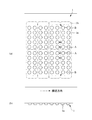
これにより、この成型装置16にて成型処理が施され、通過した容器フィルム10は、図6に示すように、成型装置16の凹部16c′に対向する位置にポケット部10aが成型される。そして、最終的に個々のPTP包装体を構成するフィルム部位は、図6中、二点鎖線で示す領域となる。図に示すように、最終的なPTP包装体において製造年月日その他の情報を刻印等するためのポケット部が形成されない平坦な余剰フィルム部分10bは、容器フィルム10の中央側の凹部未形成領域R1に形成する。これにより、横に並んだPTP包装体の余剰フィルム部分10bを内側に対向して配置した状態で、PTP包装体を製造する。
Thereby, a molding process is performed by the
このように横に並ぶPTP包装体の互いの余剰フィルム部分を内側に配置したため、打ち抜き装置27によりフィルムの適宜位置がカットされて最終的に製造されたPTP包装体の余剰フィルム部分におけるカールの発生を抑制できる。すなわち、容器フィルム10は、加熱装置15で加熱されて熱膨張し、成型装置16にてポケット部10aが成型時冷却され、その後も徐々に冷却されることで収縮する。しかし、ポケット成型装置16の温度や、その他のガイド部分の温度は一定ではなく、運転の継続にともない前記冷却部の温度が上昇することもあり容器フィルム10の収縮率が変動し、運転開始直後成型される容器フィルム成型寸法は短く、連続運転の時間が長くなるほどフィルム成型寸法は長くなる傾向にある。加えて、運転開始当初はシールされていない成型ポケットフィルムは時間経過に比例し収縮しより短くなっている。よってシール装置20にてポケット部10aを噛みこまない(シール受けローラ20aに凹部内にポケット部10aがきれいに入り込む)ようにするために、容器フィルム10の送りピッチを実際のシート寸法程度か若干長めに設定しなければならない。その結果、運転が継続するにつれて成型装置16やその他アイドルローラ17、ダンサローラ19等の温度が上昇にすることにより、容器フィルムの成型後の収縮量が減るので、容器成型フィルムピッチが製品ピッチより長くなってしまう場合がある。この状態では、容器フィルム10には、シール装置20にてシール処理される際に、所定方向のストレスが加わる。このストレスの方向は、幅方向の中央部分に位置するポケット部10a(図6中符号A)の場合、フィルムの搬送方向と平行となる。そのため、左右に配置されるPTP包装体の余剰フィルム部分は、容器フィルム10の幅方向の中央部位に位置し、互いにつながっていることもあり、隣接のポケット部10aから斜め方向のストレスを受けず、係る斜め方向のひずみも発生しない。
Since the surplus film portions of the PTP packagings arranged side by side are arranged on the inner side in this way, the occurrence of curling in the surplus film portions of the PTP packaging finally produced by cutting the appropriate position of the film by the punching
また、幅方向の両外側に位置するポケット部10a(図6中符号B)から斜め外側に向かうストレスが発生し、係る斜め外側の方向のストレス・歪みを残したまま蓋フィルム21と熱シールされて一体化され、最終的にPTP包装体30が製造される(図7参照)。しかし、係る外側には余剰フィルム部分10bがなく、係る幅方向外側に位置するポケット部10aからPTP包装体30の外周縁までが短く、曲がりにくい。また、仮に曲がったとしても、例えば図7に示すようにその変形する部分30aが小さく、目立たない。
Further, a stress is generated obliquely outward from the
上述した実施形態では、加熱装置15は容器フィルム10の全面に対して加熱したが、本発明はこれに限ることはなく、例えば、図8に示すように、加熱装置15の上部,下部加熱板15a,15bの幅方向中央部位に搬送方向に沿って伸びる凹溝15cを形成する。これにより、上下の加熱板15aで容器フィルム10を挟み込んだ際に、凹溝15cに対向するフィルム部位は加熱板15aに非接触となり加熱されず、熱膨張しない。よって、成型装置16を通過後の容器フィルム10は、図9に示すように、ポケット部10aを形成する左右の領域(ハッチングで示す)は加熱されて熱膨張し、その後に収縮するが、中央領域R2は元々熱膨張をほとんどせずに、安定した状態を保つ。係る中央領域R2は、最終的なPTP包装体における余剰フィルム部分となるため、後段のシール装置20におけるシール処理時に斜め方向のストレスによる歪みを受けにくくなり、よりきれいなPTP包装体を製造することができる。
In the embodiment described above, the
さらに加熱装置15は中央部分に加熱をひかえる構造を設けているので、たとえシート寸法が変わっても、重量があり加熱されているため取り扱いが困難な加熱装置を製品にあわせ取り替える必要はない。
Furthermore, since the
10 容器フィルム
10a ポケット部
10b 余剰フィルム部分
15 加熱装置
15c 凹溝
16 成型装置
21 蓋フィルム
DESCRIPTION OF
Claims (4)
容器フィルムに前記ポケット部を成型する成型装置と、
その成形装置の下流側に配置され、前記ポケット部に製品を供給する製品供給領域と、
その被包装物供給領域の下流側に配置され、前記容器フィルムに蓋フィルムを覆うとともに、それらを熱シールして密封するシール装置を備え、
前記成型装置は、横に並んだPTP包装体の前記余剰フィルム部分が、内側に対向するようなレイアウトとなるように前記ポケット部を成型するようにしたことを特徴とするPTP包装機。 A PTP packaging machine for manufacturing a PTP packaging body including a plurality of pocket portions and an excess film portion in which the pocket portion is not formed at one end portion in the longitudinal direction,
A molding device for molding the pocket portion into a container film;
A product supply region that is disposed downstream of the molding apparatus and supplies products to the pocket portion;
It is arranged on the downstream side of the package supply area, and includes a sealing device that covers the lid film on the container film and seals them by heat-sealing them.
The PTP packaging machine, wherein the molding unit is configured to mold the pocket portion so that the excess film portions of the PTP packaging bodies arranged side by side have a layout facing the inside.
前記加熱装置は、前記容器フィルムの幅方向中央部位に対する加熱状態を、前記ポケット部を形成する領域よりも弱くすることを特徴とする請求項1に記載のPTP包装機。 A heating device for heating the container film is provided on the upstream side of the molding device,
2. The PTP packaging machine according to claim 1, wherein the heating device weakens a heating state with respect to a central portion in the width direction of the container film as compared with a region where the pocket portion is formed.
その上下の加熱部材の少なくとも一方が、前記容器フィルムの幅方向中央部位と非接触となるようにしたことを特徴とする請求項2に記載のPTP包装機。 The heating device has a heating member that sandwiches the container film from above and below,
The PTP packaging machine according to claim 2, wherein at least one of the upper and lower heating members is not in contact with the central portion in the width direction of the container film.
横に並んだPTP包装体の前記余剰フィルム部分が、内側に対向して配置した状態で、前記PTP包装体を製造することを特徴とするPTP包装方法。 A PTP packaging method for producing a PTP packaging body comprising a plurality of pocket portions and an excess film portion in which the pocket portions are not formed at one end portion in the longitudinal direction,
A PTP packaging method, wherein the PTP packaging body is manufactured in a state where the surplus film portions of the PTP packaging body arranged side by side are arranged facing the inside.
Priority Applications (1)
| Application Number | Priority Date | Filing Date | Title |
|---|---|---|---|
| JP2013089673A JP6099470B2 (en) | 2013-04-22 | 2013-04-22 | PTP packaging method and PTP packaging machine |
Applications Claiming Priority (1)
| Application Number | Priority Date | Filing Date | Title |
|---|---|---|---|
| JP2013089673A JP6099470B2 (en) | 2013-04-22 | 2013-04-22 | PTP packaging method and PTP packaging machine |
Publications (2)
| Publication Number | Publication Date |
|---|---|
| JP2014213860A JP2014213860A (en) | 2014-11-17 |
| JP6099470B2 true JP6099470B2 (en) | 2017-03-22 |
Family
ID=51940014
Family Applications (1)
| Application Number | Title | Priority Date | Filing Date |
|---|---|---|---|
| JP2013089673A Active JP6099470B2 (en) | 2013-04-22 | 2013-04-22 | PTP packaging method and PTP packaging machine |
Country Status (1)
| Country | Link |
|---|---|
| JP (1) | JP6099470B2 (en) |
Family Cites Families (11)
| Publication number | Priority date | Publication date | Assignee | Title |
|---|---|---|---|---|
| JPS554620B2 (en) * | 1973-09-03 | 1980-01-31 | ||
| JPS63319120A (en) * | 1987-06-23 | 1988-12-27 | Shionogi & Co Ltd | Method and apparatus for forming ptp pocket |
| JPH05201407A (en) * | 1992-01-20 | 1993-08-10 | Ckd Corp | Method and device for preventing curl in packaging sheet |
| JP2690243B2 (en) * | 1992-07-23 | 1997-12-10 | シーケーディ株式会社 | Blister packaging method |
| JP3034001U (en) * | 1996-07-26 | 1997-02-14 | 株式会社岩黒製作所 | Scrap discharge device for PTP packaging machine |
| JP3093985B2 (en) * | 1997-02-05 | 2000-10-03 | シーケーディ株式会社 | Method and apparatus for preventing curling of PTP sheet |
| JP2002019734A (en) * | 2000-07-07 | 2002-01-23 | Omori Mach Co Ltd | Heating device for ptp packaging machine |
| JP2004131117A (en) * | 2002-10-09 | 2004-04-30 | Ckd Corp | Blister packaging machine and heating device therefor |
| DE102004049560B4 (en) * | 2004-10-12 | 2006-08-31 | Mediseal Gmbh | Method and device for placing tablets in the courtyards of a deep-drawn bottom sheet |
| JP4765057B2 (en) * | 2004-11-30 | 2011-09-07 | 住友ベークライト株式会社 | PTP package and manufacturing method thereof |
| JP4545664B2 (en) * | 2005-09-08 | 2010-09-15 | シーケーディ株式会社 | PTP sheet manufacturing equipment |
-
2013
- 2013-04-22 JP JP2013089673A patent/JP6099470B2/en active Active
Also Published As
| Publication number | Publication date |
|---|---|
| JP2014213860A (en) | 2014-11-17 |
Similar Documents
| Publication | Publication Date | Title |
|---|---|---|
| KR101025779B1 (en) | Thermoforming method for film on blister packing machines and apparatus for it | |
| JP2003519052A (en) | Method and apparatus for forming blisters in a strip to produce blister packs on a blister forming machine | |
| KR20190029512A (en) | Container-making device and blister packing machine with cover | |
| US11724840B2 (en) | Blister packing machine and blister pack manufacturing method | |
| JP6099470B2 (en) | PTP packaging method and PTP packaging machine | |
| JP2690243B2 (en) | Blister packaging method | |
| JP2016132212A (en) | Bag-making method, bag making machine and packaging bag | |
| JP3753976B2 (en) | Pocket part forming apparatus and blister pack manufacturing apparatus | |
| JP4754123B2 (en) | PTP packaging machine and packaging method | |
| JP5785757B2 (en) | PTP packaging machine | |
| JP5616316B2 (en) | Pocket forming apparatus and blister packaging machine | |
| JP5159716B2 (en) | PTP sheet manufacturing equipment | |
| US20210245909A1 (en) | Blister packaging machine and method for manufacturing blister pack | |
| JP6321342B2 (en) | Deep drawing packaging machine | |
| JP6821299B2 (en) | PTP sheet manufacturing equipment and PTP sheet manufacturing method | |
| JP2002019734A (en) | Heating device for ptp packaging machine | |
| JP2544669B2 (en) | Manufacturing method of PTP sheet | |
| JP3093985B2 (en) | Method and apparatus for preventing curling of PTP sheet | |
| JP7056898B2 (en) | Deep drawing packaging machine | |
| ITMO20010044A1 (en) | METHOD AND EQUIPMENT FOR THE PRODUCTION OF CONTAINER STRIPS | |
| JP2795680B2 (en) | Method for manufacturing bottom material of electronic component carrier | |
| JP3824955B2 (en) | PTP sheet manufacturing method | |
| RU2248882C1 (en) | Method of molding of a blister packing | |
| JPS63139717A (en) | Molding equipment | |
| JP2021024640A (en) | Package manufacturing apparatus |
Legal Events
| Date | Code | Title | Description |
|---|---|---|---|
| A621 | Written request for application examination |
Free format text: JAPANESE INTERMEDIATE CODE: A621 Effective date: 20160419 |
|
| A977 | Report on retrieval |
Free format text: JAPANESE INTERMEDIATE CODE: A971007 Effective date: 20170113 |
|
| TRDD | Decision of grant or rejection written | ||
| A01 | Written decision to grant a patent or to grant a registration (utility model) |
Free format text: JAPANESE INTERMEDIATE CODE: A01 Effective date: 20170207 |
|
| A61 | First payment of annual fees (during grant procedure) |
Free format text: JAPANESE INTERMEDIATE CODE: A61 Effective date: 20170221 |
|
| R150 | Certificate of patent or registration of utility model |
Ref document number: 6099470 Country of ref document: JP Free format text: JAPANESE INTERMEDIATE CODE: R150 |
|
| R157 | Certificate of patent or utility model (correction) |
Free format text: JAPANESE INTERMEDIATE CODE: R157 |
|
| R250 | Receipt of annual fees |
Free format text: JAPANESE INTERMEDIATE CODE: R250 |
|
| R250 | Receipt of annual fees |
Free format text: JAPANESE INTERMEDIATE CODE: R250 |
|
| R250 | Receipt of annual fees |
Free format text: JAPANESE INTERMEDIATE CODE: R250 |
|
| R250 | Receipt of annual fees |
Free format text: JAPANESE INTERMEDIATE CODE: R250 |
|
| R250 | Receipt of annual fees |
Free format text: JAPANESE INTERMEDIATE CODE: R250 |