EP1647377A1 - Schneidemesseranordnung an einer Konfektionierungsmachine für Papier- und Folienbahnen mit lichtemittierendes Element zur Erzeugung von Markierungen, die die gewünschte Messerposition zeigen - Google Patents
Schneidemesseranordnung an einer Konfektionierungsmachine für Papier- und Folienbahnen mit lichtemittierendes Element zur Erzeugung von Markierungen, die die gewünschte Messerposition zeigen Download PDFInfo
- Publication number
- EP1647377A1 EP1647377A1 EP04024765A EP04024765A EP1647377A1 EP 1647377 A1 EP1647377 A1 EP 1647377A1 EP 04024765 A EP04024765 A EP 04024765A EP 04024765 A EP04024765 A EP 04024765A EP 1647377 A1 EP1647377 A1 EP 1647377A1
- Authority
- EP
- European Patent Office
- Prior art keywords
- cutting blade
- adjustable
- trolley
- light
- guide rail
- Prior art date
- Legal status (The legal status is an assumption and is not a legal conclusion. Google has not performed a legal analysis and makes no representation as to the accuracy of the status listed.)
- Granted
Links
- 238000004806 packaging method and process Methods 0.000 claims description 8
- 230000005855 radiation Effects 0.000 claims description 2
- 230000001105 regulatory effect Effects 0.000 claims description 2
- XAGFODPZIPBFFR-UHFFFAOYSA-N aluminium Chemical compound [Al] XAGFODPZIPBFFR-UHFFFAOYSA-N 0.000 abstract description 2
- 229910052782 aluminium Inorganic materials 0.000 abstract description 2
- 229910052743 krypton Inorganic materials 0.000 abstract description 2
- DNNSSWSSYDEUBZ-UHFFFAOYSA-N krypton atom Chemical compound [Kr] DNNSSWSSYDEUBZ-UHFFFAOYSA-N 0.000 abstract description 2
- 230000000295 complement effect Effects 0.000 abstract 1
- 238000006073 displacement reaction Methods 0.000 description 3
- 238000004519 manufacturing process Methods 0.000 description 2
- 239000000463 material Substances 0.000 description 2
- 230000003287 optical effect Effects 0.000 description 2
- 238000012951 Remeasurement Methods 0.000 description 1
- 239000004744 fabric Substances 0.000 description 1
- 230000003993 interaction Effects 0.000 description 1
- 230000005923 long-lasting effect Effects 0.000 description 1
- 238000012858 packaging process Methods 0.000 description 1
- 239000002985 plastic film Substances 0.000 description 1
- 229920006255 plastic film Polymers 0.000 description 1
- 239000004753 textile Substances 0.000 description 1
- 238000009966 trimming Methods 0.000 description 1
Images

Classifications
-
- B—PERFORMING OPERATIONS; TRANSPORTING
- B26—HAND CUTTING TOOLS; CUTTING; SEVERING
- B26D—CUTTING; DETAILS COMMON TO MACHINES FOR PERFORATING, PUNCHING, CUTTING-OUT, STAMPING-OUT OR SEVERING
- B26D5/00—Arrangements for operating and controlling machines or devices for cutting, cutting-out, stamping-out, punching, perforating, or severing by means other than cutting
- B26D5/02—Means for moving the cutting member into its operative position for cutting
-
- B—PERFORMING OPERATIONS; TRANSPORTING
- B26—HAND CUTTING TOOLS; CUTTING; SEVERING
- B26D—CUTTING; DETAILS COMMON TO MACHINES FOR PERFORATING, PUNCHING, CUTTING-OUT, STAMPING-OUT OR SEVERING
- B26D1/00—Cutting through work characterised by the nature or movement of the cutting member or particular materials not otherwise provided for; Apparatus or machines therefor; Cutting members therefor
- B26D1/01—Cutting through work characterised by the nature or movement of the cutting member or particular materials not otherwise provided for; Apparatus or machines therefor; Cutting members therefor involving a cutting member which does not travel with the work
- B26D1/12—Cutting through work characterised by the nature or movement of the cutting member or particular materials not otherwise provided for; Apparatus or machines therefor; Cutting members therefor involving a cutting member which does not travel with the work having a cutting member moving about an axis
- B26D1/14—Cutting through work characterised by the nature or movement of the cutting member or particular materials not otherwise provided for; Apparatus or machines therefor; Cutting members therefor involving a cutting member which does not travel with the work having a cutting member moving about an axis with a circular cutting member, e.g. disc cutter
- B26D1/24—Cutting through work characterised by the nature or movement of the cutting member or particular materials not otherwise provided for; Apparatus or machines therefor; Cutting members therefor involving a cutting member which does not travel with the work having a cutting member moving about an axis with a circular cutting member, e.g. disc cutter coacting with another disc cutter
- B26D1/245—Cutting through work characterised by the nature or movement of the cutting member or particular materials not otherwise provided for; Apparatus or machines therefor; Cutting members therefor involving a cutting member which does not travel with the work having a cutting member moving about an axis with a circular cutting member, e.g. disc cutter coacting with another disc cutter for thin material, e.g. for sheets, strips or the like
-
- B—PERFORMING OPERATIONS; TRANSPORTING
- B26—HAND CUTTING TOOLS; CUTTING; SEVERING
- B26D—CUTTING; DETAILS COMMON TO MACHINES FOR PERFORATING, PUNCHING, CUTTING-OUT, STAMPING-OUT OR SEVERING
- B26D7/00—Details of apparatus for cutting, cutting-out, stamping-out, punching, perforating, or severing by means other than cutting
- B26D7/26—Means for mounting or adjusting the cutting member; Means for adjusting the stroke of the cutting member
- B26D7/2628—Means for adjusting the position of the cutting member
- B26D7/2635—Means for adjusting the position of the cutting member for circular cutters
Definitions
- the invention relates to a cutting blade arrangement on a finishing machine for paper or film webs, which are cut for further processing, with at least one along the web width adjustable cutting blade, in which the or the cutting blades are slidably and adjustably arranged on at least one guide rail of the packaging machine.
- the cutting blades are adjusted manually according to the desired cutting position, the position being determined by means of scales and templates.
- the object is achieved in that on the packaging machine in addition to the guide rail with the cutting blades a longitudinally parallel and spaced from the guide rail extending mounting rail is attached to the at least one light-emitting element, in particular laser, is arranged adjustable with visible radiation whose bundled light beam on a desired position of a cutting knife, which is located on the guide rail, is directed and generates light marks corresponding to the position, after which the cutting blade is to be aligned.
- a laser as a light-emitting element is particularly suitable because its light can be focused on a small area without having to make additional optical focusing measures.
- the light-emitting element is preferably attached to a trolley, which is arranged displaceably on the mounting rail.
- the position of the trolley and thus the laser head is determined by a precisely controllable drive.
- drives for the trolley are in particular controlled fluidic, electrical or magnetic drives, which are known per se and make the trolley highly adjustable and adjustable to the highest degree.
- Figures 1 and 2 show parts of a confectioning machine for paper and film webs 20, prepared by marginal trimming for further processing become.
- the material of the webs can also be textile webs, for example woven or knitted fabric.
- the web 20 passes through a cutting station 10 in the direction of the arrow P.
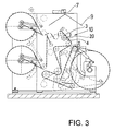
- the web 20, as can be seen from FIGS. 2 and 3, is guided over two guide rollers 11 and 21, which form part of the packaging machine shown schematically in FIG.
- the web 20 is indicated by a dashed line.
- the cutting station 10 consists of two above the track 20 arranged guide rails 1 and 2 of round aluminum rods.
- the guide rail 1 is equipped with two upper cutting blades 3 and the lower guide rail 2 with two lower cutting blades 4.
- the determination of the cutting blade 3 and 4 is carried out according to the selected position after measuring by fixing by means of screws or clamps.
- a pair of knives 3 and 4 cooperates and forms part of the cutting station 10.
- the interaction of the pairs of knives results in an exact cut S, whereby edge portions 12, 13 are cut off.
- edge portions 12, 13 are cut off.
- other cutting positions are possible.
- three or more knives may be arranged side by side, if, for example, a web is to be cut into many strips.
- an optical marking 19 is produced on the guide rail 1, 2 and on the web 20 by means of a laser beam 9 made of visible light.
- the marking 19 has the shape of a red line as a fan beam due to the design of the laser beam 9, so that by manual displacement each of the cutting blades 3 or 4 is to be aligned with this line or marking 19 which exactly corresponds to the cut S to be made. Also, a control during the operation is possible, since it is immediately recognizable when departing from the line of the cut.
- the laser beam 9 is using a laser head 7, z. B. a krypton laser head, generated and emitted via a diffuser fan beam 9, and directed to the web 20 in the region of the cutting station 10.
- the laser head 7 is connected to a trolley 6, which is movably arranged along a support rail 5.
- the support rail 5 is longitudinally parallel and spaced from the guide rail also attached to the packaging machine, for example by mounting bracket (not shown here).
- Servomotor 8 is an electronically precisely controlled stepper motor which is controlled and regulated by a stored position preset computer (not shown).
- control keyboards can be provided.
- the positions at which the cutting blades are to be determined By the operator or a predetermined program, the positions at which the cutting blades are to be determined. Programmed control is also possible to speed up the workflow.
- the laterally cut parts 12, 13 are removed from the web. Additional sensors can be used to check whether the generated cutting edge exactly meets the specifications. As a result, the tape feed and knife position can be precisely matched, even during production.
- the trolley 6 may be provided with various controllable and controllable drives, for example with fluidic, electrical or magnetic drives. Preferably, however, a program-controlled stepping motor 8 is used.
Landscapes
- Life Sciences & Earth Sciences (AREA)
- Forests & Forestry (AREA)
- Engineering & Computer Science (AREA)
- Mechanical Engineering (AREA)
- Auxiliary Devices For And Details Of Packaging Control (AREA)
- Making Paper Articles (AREA)
- Nonmetal Cutting Devices (AREA)
- Perforating, Stamping-Out Or Severing By Means Other Than Cutting (AREA)
Abstract
Description
- Die Erfindung betrifft eine Schneidmesseranordnung an einer Konfektioniermaschine für Papier- oder Folienbahnen, die zur Weiterverarbeitung geschnitten werden, mit wenigstens einem entlang der Bahnbreite einstellbaren Schneidmesser, bei der das oder die Schneidmesser verschiebbar und justierbar an wenigstens einer Führungsschiene der Konfektioniermaschine angeordnet sind.
- Bei Konfektioniermaschinen mit einer Schneidmesseranordnung werden die Schneidmesser entsprechend der gewünschten Schnittposition manuell eingestellt, wobei mithilfe von Maßstäben und Schablonen die Position festgelegt wird.
- Nachteilig hierbei ist, dass bei einer seitlichen Verstellung der Schneidmesser im Laufe des Produktionsprozesses diese Fehler kaum bemerkt werden, da eine schwache seitliche Verschiebung nicht beobachtet werden kann. Weiterhin ist bei einer Änderung der Position der Schneidmesser eine umständliche Neujustierung und Neuvermessung erforderlich.
- Es stellt sich die Aufgabe, bei einer Schneidmesseranordnung an einer Konfektioniermaschine hier die Einstellung zu vereinfachen, wobei es möglich sein soll, dass während des teilweise lang dauernden Konfektionierablaufes eine Beobachtung der Position der Schneidmesser in einfacher Weise möglich sein soll.
- Die Aufgabe wird dadurch gelöst, dass an der Konfektioniermaschine zusätzlich zu der Führungsschiene mit den Schneidmessern eine längsparallel und beabstandet gegenüber der Führungsschiene verlaufende Tragschiene angebracht ist, an der wenigstens ein lichtemittierendes Element, insbesondere Laser, mit sichtbarer Strahlung verstellbar angeordnet ist, dessen gebündelter Lichtstrahl auf eine gewünschte Position eines Schneidmessers, das sich auf der Führungsschiene befindet, gerichtet ist und Lichtmarkierungen erzeugt, die der Position entsprechen, nach der das Schneidmesser auszurichten ist.
- Ein Laser als lichtemittierendes Element ist besonders geeignet, da sein Licht auf eine kleine Fläche gebündelt werden kann, ohne dass zusätzliche optische Fokussierungsmaßnahmen getroffen werden müssen.
- Üblicherweise sind mehrere, d.h. wenigstens zwei Schneidmesser an zwei unmittelbar benachbarten Führungsschienen beweglich angebracht, so dass wenigstens zwei Positionen, gegebenenfalls auch mehr, markiert werden müssen. Daher wird vorzugsweise das lichtemittierende Element an einer Laufkatze angebracht, die an der Tragschiene verschiebbar angeordnet ist.
- Um eine reproduzierbare und genaue Position der Schneidmesser zu garantieren, wird die Position der Laufkatze und damit der Laserkopfes durch einen präzise steuerbaren Antrieb festgelegt. Als Antriebe für die Laufkatze eignen sich insbesondere geregelte fluidische, elektrische oder magnetische Antriebe, die an sich bekannt sind und die die Laufkatze in höchstem Maße präzise verstellbar und justierbar machen.
- Als weitere vorteilhafte Maßnahme zur Handhabung der Schneidmesseranordnung wird vorgeschlagen, die Laufkatze mithilfe eines programmgesteuerten Schrittmotors justierbar zu machen.
- Ein Ausführungsbeispiel der Erfindung wird anhand der Zeichnung erläutert. Die Figuren der Zeichnung zeigen:
- Fig. 1
- eine schematische Darstellung der an Führungsschienen einer Konfektioniermaschine befestigten Schneidmeser mit Tragschienen und lichtemittierendem Element;
- Fig. 2
- die Anordnung gemäß Fig. 1 in Achsenrichtung der Führungsschienen gesehen, und
- Fig. 3
- schematisch eine Konfektioniermaschine mit eingebauter Anordnung gemäß der Fig.1, ebenfalls in Achsenrichtung der Führungsschienen gesehen.
- Die Figuren 1 und 2 zeigen Teile einer Konfektioniermaschine für Papier- und Folienbahnen 20, die durch randseitiges Beschneiden für eine Weiterverarbeitung vorbereitet werden. Bei dem Material der Bahnen kann es sich außer Papier oder Kunststoff-Folien auch um textile Bahnen, beispielsweise Gewebe oder Gewirke, handeln. Dabei durchläuft die Bahn 20 in Pfeilrichtung P eine Schneidstation 10. Die Bahn 20 wird, wie aus den Figuren 2 und 3 zu ersehen, über zwei Führungsrollen 11 und 21 geführt, die Bestandteil der schematisch in Fig. 3 dargestellten Konfektioniermaschine sind. Hierbei ist die Bahn 20 mit einer Strichlinie angedeutet.
- Die Schneidstation 10 besteht aus zwei oberhalb der Bahn 20 angeordneten Führungsschienen 1 und 2 aus runden Aluminium-Stäben. Die Führungsschiene 1 ist mit zwei oberen Schneidmessern 3 und die untere Führungsschiene 2 mit zwei unteren Schneidmessern 4 bestückt. Die Festlegung der Schneidmesser 3 und 4 erfolgt entsprechend der gewählten Position nach Ausmessen durch Festlegung mittels Schrauben oder Klemmen.
- Jeweils ein Messerpaar 3 und 4 wirkt zusammen und bildet einen Teil der Schneidstation 10. Das Zusammenwirken der Messerpaare ergibt einen exakten Schnitt S, wobei randseitig Abfallteile 12, 13 abgeschnitten werden. Selbstverständlich sind auch andere Schneidpositionen möglich. Beispielsweise können auch drei oder mehr Messer nebeneinander angeordnet sein, wenn zum Beispiel eine Bahn in viele Streifen zerschnitten werden soll.
- Wesentliche Voraussetzung für ein brauchbares Arbeitsergebnis ist eine exakte Einstellung der Position der Schneidmesser 3, 4, da das Material zur Weiterverarbeitung bestimmt ist.
- Um die Schneidmesser 3, 4 exakt positionieren zu können, wird mithilfe eines aus sichtbarem Licht bestehenden Laserstrahls 9 eine optische Markierung 19 auf der Führungsschiene 1, 2 und auf der Bahn 20 erzeugt. Die Markierung 19 hat durch die Gestaltung des Laserstrahls 9 als Fächerstrahl die Gestalt einer roten Linie, so dass per Handverschiebung jedes der Schneidmesser 3 oder 4 an dieser Linie bzw. Markierung 19 auszurichten ist, die exakt dem durchzuführenden Schnitt S entspricht. Auch ist eine Kontrolle während des Arbeitsvorganges möglich, da bei Abweichen des Schnittes von der Linie dies sofort zu erkennen ist.
- Der Laserstrahl 9 wird mithilfe eines Laserkopfes 7, z. B. eines Krypton-Laserkopfes, über einen Diffusor als Fächerstrahl 9 erzeugt und abgestrahlt, und auf die Bahn 20 im Bereich der Schneidstation 10 gerichtet. Der Laserkopf 7 ist mit einer Laufkatze 6 verbunden, die entlang einer Tragschiene 5 beweglich angeordnet ist. Die Tragschiene 5 ist längs parallel und beabstandet gegenüber der Führungsschiene ebenfalls an der Konfektioniermaschine befestigt, beispielsweise durch Tragbügel (hier nicht dargestellt). Mithilfe eines Servomotors 8 wird eine Verschiebung der Laufkatze 6 von der Position I (links) zu einer Position II (rechts) ermöglicht. Der Servomotor 8 ist ein elektronisch präzise geregelter Schrittmotor, der über einen Computer (nicht dargestellt) mit gespeicherter Positionsvorgabe gesteuert und geregelt wird.
- Hierzu können entsprechende Steuerungstastaturen, (Touch-Screen-Elemente) vorgesehen werden. Durch die Bedienungsperson oder ein vorgegebenes Programm können die Positionen bestimmt werden, an denen sich die Schneidmesser befinden sollen. Auch ist eine programmierte Steuerung möglich, um den Arbeitsablauf zu beschleunigen.
- Die seitlich abgeschnittenen Teile 12, 13 werden von der Bahn entfernt. Durch zusätzliche Sensoren kann kontrolliert werden, ob die erzeugte Schnittkante genau den Vorgaben entspricht. Hierdurch können Bandeinlauf und Messerposition exakt aufeinander abgestimmt werden, auch während der Produktion.
- Die Laufkatze 6 kann mit verschiedenen steuer- und regelbaren Antrieben versehen sein, beispielsweise mit fluidischen, elektrischen oder magnetischen Antrieben. Vorzugsweise wird jedoch ein programmgesteuerter Schrittmotor 8 verwendet.
Claims (6)
- Schneidmesseranordnung an einer Konfektioniermaschine für Papier- oder Folienbahnen, die zur Weiterverarbeitung geschnitten werden, mit wenigstens einem entlang der Bahnbreite einstellbaren Schneidmesser, bei der das oder die Schneidmesser (3, 4) verschiebbar und justierbar an wenigstens einer Führungsschiene (1, 2) der Konfektioniermaschine angeordnet sind,
dadurch gekennzeichnet, dass
an der Konfektioniermaschine eine längsparallel und beabstandet gegenüber der Führungsschiene (1, 2) verlaufende Tragschiene (5) angebracht ist, an der wenigstens ein lichtemittierendes Element, insbesondere Laser (7), mit sichtbarer Strahlung verstellbar angeordnet ist, dessen gebündelter Lichtstrahl (9) auf eine gewünschte Position eines Schneidmessers (3, 4), das sich auf der Führungsschiene (1, 2) befindet, gerichtet ist und Markierungen (19) erzeugt, die der Position entsprechen, nach der das Schneidmesser (3, 4) auszurichten ist. - Schneidmesseranordnung nach Anspruch 1, dadurch gekennzeichnet, dass mit dem lichtemittierenden Element ein Fächerstrahl (9) erzeugbar ist, mit dem sich als Markierung (19) eine Linie in Schnittrichtung ergibt.
- Vorrichtung nach Anspruch 1 oder 2, dadurch gekennzeichnet, dass das lichtemittierende Element (7) an einer Laufkatze (6) angebracht ist, die an der Tragschiene (5) verschiebbar angeordnet ist.
- Vorrichtung nach Anspruch 1 bis 3, dadurch gekennzeichnet, dass die Position der Laufkatze (6) und damit des Laserkopfes (7) durch einen präzise steuerbaren Antrieb festlegbar ist.
- Vorrichtung nach Anspruch 4 dadurch gekennzeichnet, dass die Laufkatze (6) mittels eines geregelten fluidischen, elektrischen oder magnetischen Antriebs verstellbar und justierbar ist.
- Vorrichtung nach einem der vorhergehenden Ansprüche, dadurch gekennzeichnet, dass die Laufkatze (6) mithilfe eines programmgesteuerten Schrittmotors (8) justierbar ist.
Priority Applications (3)
| Application Number | Priority Date | Filing Date | Title |
|---|---|---|---|
| EP04024765A EP1647377B1 (de) | 2004-10-18 | 2004-10-18 | Schneidemesseranordnung an einer Konfektionierungsmachine für Papier- und Folienbahnen mit lichtemittierendes Element zur Erzeugung von Markierungen, die die gewünschte Messerposition zeigen |
| AT04024765T ATE354459T1 (de) | 2004-10-18 | 2004-10-18 | Schneidemesseranordnung an einer konfektionierungsmachine für papier- und folienbahnen mit lichtemittierendes element zur erzeugung von markierungen, die die gewünschte messerposition zeigen |
| DE502004002975T DE502004002975D1 (de) | 2004-10-18 | 2004-10-18 | Schneidemesseranordnung an einer Konfektionierungsmachine für Papier- und Folienbahnen mit lichtemittierendes Element zur Erzeugung von Markierungen, die die gewünschte Messerposition zeigen |
Applications Claiming Priority (1)
| Application Number | Priority Date | Filing Date | Title |
|---|---|---|---|
| EP04024765A EP1647377B1 (de) | 2004-10-18 | 2004-10-18 | Schneidemesseranordnung an einer Konfektionierungsmachine für Papier- und Folienbahnen mit lichtemittierendes Element zur Erzeugung von Markierungen, die die gewünschte Messerposition zeigen |
Publications (2)
| Publication Number | Publication Date |
|---|---|
| EP1647377A1 true EP1647377A1 (de) | 2006-04-19 |
| EP1647377B1 EP1647377B1 (de) | 2007-02-21 |
Family
ID=34927017
Family Applications (1)
| Application Number | Title | Priority Date | Filing Date |
|---|---|---|---|
| EP04024765A Expired - Lifetime EP1647377B1 (de) | 2004-10-18 | 2004-10-18 | Schneidemesseranordnung an einer Konfektionierungsmachine für Papier- und Folienbahnen mit lichtemittierendes Element zur Erzeugung von Markierungen, die die gewünschte Messerposition zeigen |
Country Status (3)
| Country | Link |
|---|---|
| EP (1) | EP1647377B1 (de) |
| AT (1) | ATE354459T1 (de) |
| DE (1) | DE502004002975D1 (de) |
Cited By (2)
| Publication number | Priority date | Publication date | Assignee | Title |
|---|---|---|---|---|
| EP2353823A1 (de) * | 2010-02-08 | 2011-08-10 | Freymatic AG | Positioniervorrichtung für verstellbare Elemente, Verfahren zum Positionieren von verstellbaren Elementen und Verwendung einer Positioniervorrichtung |
| EP2769813A2 (de) | 2013-02-22 | 2014-08-27 | Valmet Technologies, Inc. | Verfahren zur Kalibrierung der Position der Rollenschneidklingen eines Rollenschneiders |
Families Citing this family (3)
| Publication number | Priority date | Publication date | Assignee | Title |
|---|---|---|---|---|
| US9138905B2 (en) * | 2013-02-22 | 2015-09-22 | Valmet Technologies, Inc. | Method for calibrating the position of the slitter blades of a slitter-winder |
| CN104552430B (zh) * | 2015-01-28 | 2017-03-15 | 联盛纸业(龙海)有限公司 | 一种自动调刀器及其使用方法 |
| CN107881628B (zh) * | 2017-10-30 | 2020-06-16 | 江苏莱纳多智能装备有限公司 | 一种夹块调节型双层织物切割装置 |
Citations (2)
| Publication number | Priority date | Publication date | Assignee | Title |
|---|---|---|---|---|
| US4163185A (en) * | 1976-03-04 | 1979-07-31 | Rengo Co., Ltd. | Object locating apparatus |
| EP1207026A2 (de) * | 2000-11-17 | 2002-05-22 | Heidelberger Druckmaschinen Aktiengesellschaft | Justiereinrichtung sowie Verfahren zur Voreinstellung einer Schneideinrichtung |
-
2004
- 2004-10-18 DE DE502004002975T patent/DE502004002975D1/de not_active Expired - Lifetime
- 2004-10-18 EP EP04024765A patent/EP1647377B1/de not_active Expired - Lifetime
- 2004-10-18 AT AT04024765T patent/ATE354459T1/de not_active IP Right Cessation
Patent Citations (2)
| Publication number | Priority date | Publication date | Assignee | Title |
|---|---|---|---|---|
| US4163185A (en) * | 1976-03-04 | 1979-07-31 | Rengo Co., Ltd. | Object locating apparatus |
| EP1207026A2 (de) * | 2000-11-17 | 2002-05-22 | Heidelberger Druckmaschinen Aktiengesellschaft | Justiereinrichtung sowie Verfahren zur Voreinstellung einer Schneideinrichtung |
Cited By (2)
| Publication number | Priority date | Publication date | Assignee | Title |
|---|---|---|---|---|
| EP2353823A1 (de) * | 2010-02-08 | 2011-08-10 | Freymatic AG | Positioniervorrichtung für verstellbare Elemente, Verfahren zum Positionieren von verstellbaren Elementen und Verwendung einer Positioniervorrichtung |
| EP2769813A2 (de) | 2013-02-22 | 2014-08-27 | Valmet Technologies, Inc. | Verfahren zur Kalibrierung der Position der Rollenschneidklingen eines Rollenschneiders |
Also Published As
| Publication number | Publication date |
|---|---|
| DE502004002975D1 (de) | 2007-04-05 |
| ATE354459T1 (de) | 2007-03-15 |
| EP1647377B1 (de) | 2007-02-21 |
Similar Documents
| Publication | Publication Date | Title |
|---|---|---|
| EP1972401B1 (de) | Vorrichtung zum Schneiden von Bändern, Blechen oder dergleichen und Verfahren zur Bestimmung und/oder Kalibrierung des Schneidspaltes bei einer solchen Vorrichtung | |
| EP2143517B1 (de) | Verfahren zum Betreiben einer Plattenaufteilanlage für großformatige plattenförmige Werkstücke, insbesondere Möbelteile, sowie Plattenaufteilanlage | |
| DE102007023457A1 (de) | Verfahren zur automatischen Annäherung eines dünn zu schneidenden Präparates an das Messer eines Mikrotoms | |
| DE3035962C3 (de) | Vorrichtung zum Steuern der Antriebe einer Bandsägemaschine | |
| DE2638735C3 (de) | Anordnung zur Stellungsvorgabe bei einer Positioniervorrichtung | |
| EP1647377B1 (de) | Schneidemesseranordnung an einer Konfektionierungsmachine für Papier- und Folienbahnen mit lichtemittierendes Element zur Erzeugung von Markierungen, die die gewünschte Messerposition zeigen | |
| DE3203943C2 (de) | ||
| DE3406904A1 (de) | Vorrichtung und verfahren zum zuschneiden von plattengut | |
| DE102017112754A1 (de) | Verfahren zum Schneiden von Bögen sowie Schneidmaschine | |
| EP0406219B1 (de) | Vorrichtung zum Zerteilen von Werkstücken, insbesondere von Holz | |
| DE3925472C2 (de) | Verfahren und Vorrichtung zum Schneiden von Sandwichpaneelen | |
| EP0947880A1 (de) | Verfahren und Vorrichtung zum Schneiden von Materialbahnen mit darauf befindlichen Bildern | |
| DE4223966C1 (de) | Näheinheit zur Herstellung eines Tascheneingriffs | |
| DE10393022T5 (de) | Verfahren und Vorrichtung zum Kalibrieren der Position von Klingen einer Rollenschneidmaschine von einer Papiermaschine oder Kartonmaschine | |
| DE112009001353T5 (de) | Verfahren zum Kalibrieren der Position von Klingen eines Rollenschneiders in einer Faserbahnmaschine und das Verfahren anwendende Vorrichtung | |
| DE10235903B4 (de) | Verfahren und Vorrichtung zum Schneiden von Blechplatinen mit einem Schneidstrahl | |
| DE102010000674A1 (de) | Vorrichtung zum teilweisen Durchtrennen eines Werkstücks | |
| DE4107227C2 (de) | ||
| DE102014208304A1 (de) | Maschine zum Bearbeiten von Holzplatten | |
| EP2656985A1 (de) | Schneidmaschine zum Schneiden von gestapeltem, blattförmigem Gut | |
| DE2402311A1 (de) | Arbeitsmaschine zum geradlinig fortschreitenden bearbeiten eines auf einem arbeitstisch mit hoehenverstellbarer tischplatte liegenden, verschiebbaren, plattenfoermigen werkstueckes aus gestein, z.b. marmor | |
| DE3630908A1 (de) | Doppelgehrungssaegevorrichtung zum zuschneiden von profilen | |
| DE202005016168U1 (de) | Vorrichtung zum Ablängen von dünnwandigen hohlen Kunststoffprofilen | |
| EP4429854B1 (de) | Positionierung eines positionsveränderlichen anschlagmittels einer aufschneidevorrichtung zum aufschneiden von lebensmitteln | |
| EP2586553B1 (de) | Vorrichtung und Verfahren zum Herstellen einer Nut in Werkstücken |
Legal Events
| Date | Code | Title | Description |
|---|---|---|---|
| PUAI | Public reference made under article 153(3) epc to a published international application that has entered the european phase |
Free format text: ORIGINAL CODE: 0009012 |
|
| AK | Designated contracting states |
Kind code of ref document: A1 Designated state(s): AT BE BG CH CY CZ DE DK EE ES FI FR GB GR HU IE IT LI LU MC NL PL PT RO SE SI SK TR |
|
| AX | Request for extension of the european patent |
Extension state: AL HR LT LV MK |
|
| 17P | Request for examination filed |
Effective date: 20060427 |
|
| GRAP | Despatch of communication of intention to grant a patent |
Free format text: ORIGINAL CODE: EPIDOSNIGR1 |
|
| GRAS | Grant fee paid |
Free format text: ORIGINAL CODE: EPIDOSNIGR3 |
|
| AKX | Designation fees paid |
Designated state(s): AT BE BG CH CY CZ DE DK EE ES FI FR GB GR HU IE IT LI LU MC NL PL PT RO SE SI SK TR |
|
| GRAA | (expected) grant |
Free format text: ORIGINAL CODE: 0009210 |
|
| AK | Designated contracting states |
Kind code of ref document: B1 Designated state(s): AT BE BG CH CY CZ DE DK EE ES FI FR GB GR HU IE IT LI LU MC NL PL PT RO SE SI SK TR |
|
| PG25 | Lapsed in a contracting state [announced via postgrant information from national office to epo] |
Ref country code: IE Free format text: LAPSE BECAUSE OF FAILURE TO SUBMIT A TRANSLATION OF THE DESCRIPTION OR TO PAY THE FEE WITHIN THE PRESCRIBED TIME-LIMIT Effective date: 20070221 Ref country code: NL Free format text: LAPSE BECAUSE OF FAILURE TO SUBMIT A TRANSLATION OF THE DESCRIPTION OR TO PAY THE FEE WITHIN THE PRESCRIBED TIME-LIMIT Effective date: 20070221 Ref country code: FI Free format text: LAPSE BECAUSE OF FAILURE TO SUBMIT A TRANSLATION OF THE DESCRIPTION OR TO PAY THE FEE WITHIN THE PRESCRIBED TIME-LIMIT Effective date: 20070221 Ref country code: DK Free format text: LAPSE BECAUSE OF FAILURE TO SUBMIT A TRANSLATION OF THE DESCRIPTION OR TO PAY THE FEE WITHIN THE PRESCRIBED TIME-LIMIT Effective date: 20070221 Ref country code: PL Free format text: LAPSE BECAUSE OF FAILURE TO SUBMIT A TRANSLATION OF THE DESCRIPTION OR TO PAY THE FEE WITHIN THE PRESCRIBED TIME-LIMIT Effective date: 20070221 Ref country code: SI Free format text: LAPSE BECAUSE OF FAILURE TO SUBMIT A TRANSLATION OF THE DESCRIPTION OR TO PAY THE FEE WITHIN THE PRESCRIBED TIME-LIMIT Effective date: 20070221 |
|
| REG | Reference to a national code |
Ref country code: GB Ref legal event code: FG4D Free format text: NOT ENGLISH |
|
| REG | Reference to a national code |
Ref country code: CH Ref legal event code: EP |
|
| REF | Corresponds to: |
Ref document number: 502004002975 Country of ref document: DE Date of ref document: 20070405 Kind code of ref document: P |
|
| REG | Reference to a national code |
Ref country code: IE Ref legal event code: FG4D Free format text: LANGUAGE OF EP DOCUMENT: GERMAN |
|
| PG25 | Lapsed in a contracting state [announced via postgrant information from national office to epo] |
Ref country code: SE Free format text: LAPSE BECAUSE OF FAILURE TO SUBMIT A TRANSLATION OF THE DESCRIPTION OR TO PAY THE FEE WITHIN THE PRESCRIBED TIME-LIMIT Effective date: 20070521 |
|
| PG25 | Lapsed in a contracting state [announced via postgrant information from national office to epo] |
Ref country code: BG Free format text: LAPSE BECAUSE OF FAILURE TO SUBMIT A TRANSLATION OF THE DESCRIPTION OR TO PAY THE FEE WITHIN THE PRESCRIBED TIME-LIMIT Effective date: 20070522 |
|
| PG25 | Lapsed in a contracting state [announced via postgrant information from national office to epo] |
Ref country code: ES Free format text: LAPSE BECAUSE OF FAILURE TO SUBMIT A TRANSLATION OF THE DESCRIPTION OR TO PAY THE FEE WITHIN THE PRESCRIBED TIME-LIMIT Effective date: 20070601 |
|
| PG25 | Lapsed in a contracting state [announced via postgrant information from national office to epo] |
Ref country code: PT Free format text: LAPSE BECAUSE OF FAILURE TO SUBMIT A TRANSLATION OF THE DESCRIPTION OR TO PAY THE FEE WITHIN THE PRESCRIBED TIME-LIMIT Effective date: 20070723 |
|
| NLV1 | Nl: lapsed or annulled due to failure to fulfill the requirements of art. 29p and 29m of the patents act | ||
| GBV | Gb: ep patent (uk) treated as always having been void in accordance with gb section 77(7)/1977 [no translation filed] |
Effective date: 20070221 |
|
| REG | Reference to a national code |
Ref country code: IE Ref legal event code: FD4D |
|
| EN | Fr: translation not filed | ||
| PG25 | Lapsed in a contracting state [announced via postgrant information from national office to epo] |
Ref country code: GB Free format text: LAPSE BECAUSE OF FAILURE TO SUBMIT A TRANSLATION OF THE DESCRIPTION OR TO PAY THE FEE WITHIN THE PRESCRIBED TIME-LIMIT Effective date: 20070221 Ref country code: SK Free format text: LAPSE BECAUSE OF FAILURE TO SUBMIT A TRANSLATION OF THE DESCRIPTION OR TO PAY THE FEE WITHIN THE PRESCRIBED TIME-LIMIT Effective date: 20070221 |
|
| PLBE | No opposition filed within time limit |
Free format text: ORIGINAL CODE: 0009261 |
|
| STAA | Information on the status of an ep patent application or granted ep patent |
Free format text: STATUS: NO OPPOSITION FILED WITHIN TIME LIMIT |
|
| PG25 | Lapsed in a contracting state [announced via postgrant information from national office to epo] |
Ref country code: CZ Free format text: LAPSE BECAUSE OF FAILURE TO SUBMIT A TRANSLATION OF THE DESCRIPTION OR TO PAY THE FEE WITHIN THE PRESCRIBED TIME-LIMIT Effective date: 20070221 Ref country code: RO Free format text: LAPSE BECAUSE OF FAILURE TO SUBMIT A TRANSLATION OF THE DESCRIPTION OR TO PAY THE FEE WITHIN THE PRESCRIBED TIME-LIMIT Effective date: 20070221 |
|
| 26N | No opposition filed |
Effective date: 20071122 |
|
| BERE | Be: lapsed |
Owner name: JURMET SP. Z O.O. Effective date: 20071031 |
|
| PG25 | Lapsed in a contracting state [announced via postgrant information from national office to epo] |
Ref country code: FR Free format text: LAPSE BECAUSE OF FAILURE TO SUBMIT A TRANSLATION OF THE DESCRIPTION OR TO PAY THE FEE WITHIN THE PRESCRIBED TIME-LIMIT Effective date: 20071012 Ref country code: GR Free format text: LAPSE BECAUSE OF FAILURE TO SUBMIT A TRANSLATION OF THE DESCRIPTION OR TO PAY THE FEE WITHIN THE PRESCRIBED TIME-LIMIT Effective date: 20070522 Ref country code: IT Free format text: LAPSE BECAUSE OF FAILURE TO SUBMIT A TRANSLATION OF THE DESCRIPTION OR TO PAY THE FEE WITHIN THE PRESCRIBED TIME-LIMIT Effective date: 20070221 |
|
| PG25 | Lapsed in a contracting state [announced via postgrant information from national office to epo] |
Ref country code: MC Free format text: LAPSE BECAUSE OF NON-PAYMENT OF DUE FEES Effective date: 20071031 |
|
| PG25 | Lapsed in a contracting state [announced via postgrant information from national office to epo] |
Ref country code: BE Free format text: LAPSE BECAUSE OF NON-PAYMENT OF DUE FEES Effective date: 20071031 |
|
| PG25 | Lapsed in a contracting state [announced via postgrant information from national office to epo] |
Ref country code: FR Free format text: LAPSE BECAUSE OF FAILURE TO SUBMIT A TRANSLATION OF THE DESCRIPTION OR TO PAY THE FEE WITHIN THE PRESCRIBED TIME-LIMIT Effective date: 20070221 |
|
| PG25 | Lapsed in a contracting state [announced via postgrant information from national office to epo] |
Ref country code: EE Free format text: LAPSE BECAUSE OF FAILURE TO SUBMIT A TRANSLATION OF THE DESCRIPTION OR TO PAY THE FEE WITHIN THE PRESCRIBED TIME-LIMIT Effective date: 20070221 |
|
| PG25 | Lapsed in a contracting state [announced via postgrant information from national office to epo] |
Ref country code: AT Free format text: LAPSE BECAUSE OF NON-PAYMENT OF DUE FEES Effective date: 20071018 |
|
| REG | Reference to a national code |
Ref country code: CH Ref legal event code: PL |
|
| PG25 | Lapsed in a contracting state [announced via postgrant information from national office to epo] |
Ref country code: CY Free format text: LAPSE BECAUSE OF FAILURE TO SUBMIT A TRANSLATION OF THE DESCRIPTION OR TO PAY THE FEE WITHIN THE PRESCRIBED TIME-LIMIT Effective date: 20070221 |
|
| PG25 | Lapsed in a contracting state [announced via postgrant information from national office to epo] |
Ref country code: LU Free format text: LAPSE BECAUSE OF NON-PAYMENT OF DUE FEES Effective date: 20071018 |
|
| PG25 | Lapsed in a contracting state [announced via postgrant information from national office to epo] |
Ref country code: HU Free format text: LAPSE BECAUSE OF FAILURE TO SUBMIT A TRANSLATION OF THE DESCRIPTION OR TO PAY THE FEE WITHIN THE PRESCRIBED TIME-LIMIT Effective date: 20070822 Ref country code: TR Free format text: LAPSE BECAUSE OF FAILURE TO SUBMIT A TRANSLATION OF THE DESCRIPTION OR TO PAY THE FEE WITHIN THE PRESCRIBED TIME-LIMIT Effective date: 20070221 |
|
| PG25 | Lapsed in a contracting state [announced via postgrant information from national office to epo] |
Ref country code: CH Free format text: LAPSE BECAUSE OF NON-PAYMENT OF DUE FEES Effective date: 20081031 Ref country code: LI Free format text: LAPSE BECAUSE OF NON-PAYMENT OF DUE FEES Effective date: 20081031 |
|
| PGFP | Annual fee paid to national office [announced via postgrant information from national office to epo] |
Ref country code: DE Payment date: 20111229 Year of fee payment: 8 |
|
| PG25 | Lapsed in a contracting state [announced via postgrant information from national office to epo] |
Ref country code: DE Free format text: LAPSE BECAUSE OF NON-PAYMENT OF DUE FEES Effective date: 20130501 |
|
| REG | Reference to a national code |
Ref country code: DE Ref legal event code: R119 Ref document number: 502004002975 Country of ref document: DE Effective date: 20130501 |