EP1647219B1 - Saugvorsatz mit Kupplungsvorrichtung für Staubsauger - Google Patents
Saugvorsatz mit Kupplungsvorrichtung für Staubsauger Download PDFInfo
- Publication number
- EP1647219B1 EP1647219B1 EP05018243A EP05018243A EP1647219B1 EP 1647219 B1 EP1647219 B1 EP 1647219B1 EP 05018243 A EP05018243 A EP 05018243A EP 05018243 A EP05018243 A EP 05018243A EP 1647219 B1 EP1647219 B1 EP 1647219B1
- Authority
- EP
- European Patent Office
- Prior art keywords
- pivot
- connection
- rotary element
- rotary
- pivot element
- Prior art date
- Legal status (The legal status is an assumption and is not a legal conclusion. Google has not performed a legal analysis and makes no representation as to the accuracy of the status listed.)
- Expired - Lifetime
Links
Images

Classifications
-
- A—HUMAN NECESSITIES
- A47—FURNITURE; DOMESTIC ARTICLES OR APPLIANCES; COFFEE MILLS; SPICE MILLS; SUCTION CLEANERS IN GENERAL
- A47L—DOMESTIC WASHING OR CLEANING; SUCTION CLEANERS IN GENERAL
- A47L9/00—Details or accessories of suction cleaners, e.g. mechanical means for controlling the suction or for effecting pulsating action; Storing devices specially adapted to suction cleaners or parts thereof; Carrying-vehicles specially adapted for suction cleaners
- A47L9/02—Nozzles
Definitions
- the invention relates to a suction attachment for a floor care device, in particular vacuum cleaner, for pivotable and rotatable connection via a connection of the suction attachment with a suction port and handle of the floor care device, wherein a pivot member is pivotally mounted on the suction attachment and with a corresponding rotary member having a connection to Floor care device forms, is coupled to the rotatable connection and pivot element and rotary element interlock and in the connection region of the pivot member and rotary member via a groove in the pivot member and corresponding elements on the rotary member a guide is feasible.
- JP 11206654 A It is known to assign by an arrangement of two usable and fixable guide elements in openings of a rotary element, the guide elements of a corresponding groove of the pivot member, thereby achieving a guide and support. As a result, no robust assignment of pivoting and rotating element is ensured and achieved by the external accessibility of the guide elements no hedging.
- the object of the invention is to provide a generic arrangement of a suction attachment for connection to a ground care device by simpler means, which ensures a holder and guide and ensures assembly and disassembly of relatively tightly associated elements.
- each circumferential, mutually associated grooves on the pivot member and rotary member for receiving sections and forming a guiding and retaining ring, said sections over at least one coverable by one or more closure elements and / or lockable Opening in the outer element can be inserted into the grooves.
- a favorable education is created by the fact that the rotary member engages in the connecting area to the pivot member sleeve-shaped over the pivot member.
- the pivot member engages sleeve-shaped over the rotary member in the connection region to the rotary member.
- one of the grooves has at least one limited pocket-shaped receptacle for fixing one or more sections.
- the pivoting element can be blocked via an associated locking element against a tilting movement.
- the locking element is formed by a foot-actuated rocker on the suction attachment.
- a functionally reliable arrangement is provided in that a closure element is formed by a lockable cover on the sleeve-shaped element.
- a favorable education is created by the fact that the rotary element is part of the floor care device, which can be coupled to the suction attachment in the connection point to the pivoting element.
- connection region between the pivot element and the rotary member for receiving the grooves is formed like a bead.
- a conventional suction attachment (1) is provided for a carpet cleaning device having a suction port in the form of a pivoting element (2).
- a corresponding cross-over rotary element (3) is placed, which is rotatably adjustable relative to the pivoting element (2).
- the Swivel element (2) and the rotary element (3) form a connecting piece, in which a filter housing with its handle via a connecting piece in a known manner can be used.
- a coupling of pivoting element (2) and rotary element (3) takes place in each case via circumferential, mutually associated grooves (4, 5) for receiving usable adapted sections (6) to form a guiding and retaining ring (7).
- the partial elements (6) are inserted into the grooves (4, 5) via an opening (8) in the rotary element (3) and the opening (8) is closed or released by a lockable cover (9).
- a spring-loaded detent (10) mounted in the pivot element (2) engages in an abutment (13) arranged in the rotary element (3) to perform a corresponding locking of the rotational movement in the rest position and on the suction attachment (1) arranged with the pivot element (2) corresponding locking element (12) serves to lock the pivoting movement.
- the catch (10) is actuated by a slider (14) corresponding to the suction attachment (1) only in the rest position, and thus in the vertical orientation of the pivoting element (2).
- the locking element (12) is actuated and the arrangement is pivoted.
- the spring-loaded catch (10) engages in a counter-bearing (13) arranged in the rotary element (3) and is released again when the rotary element (3) is pivoted.
Landscapes
- Engineering & Computer Science (AREA)
- Mechanical Engineering (AREA)
- Nozzles For Electric Vacuum Cleaners (AREA)
- Electric Vacuum Cleaner (AREA)
- Quick-Acting Or Multi-Walled Pipe Joints (AREA)
- Manipulator (AREA)
- Hooks, Suction Cups, And Attachment By Adhesive Means (AREA)
Description
- Die Erfindung bezieht sich auf einen Saugvorsatz für ein Bodenpflegegerät, insbesondere Staubsauger, zur verschwenkbaren und drehbeweglichen Verbindung über einen Anschluß des Saugvorsatzes mit einem Sauganschluß und Handhabe des Bodenpflegegerätes, wobei ein Schwenkelement am Saugvorsatz schwenkbar angeordnet ist und mit einem korrespondierenden Drehelement, das einen Anschluß zum Bodenpflegegerät bildet, zur drehbeweglichen Verbindung gekoppelt ist sowie Schwenkelement und Drehelement ineinander greifen und im Verbindungsbereich von Schwenkelement und Drehelement über eine Nut im Schwenkelement und korrespondierende Elemente am Drehelement eine Führung durchführbar ist.
- Es hat sich gezeigt, daß es relativ aufwendig ist, eine verschwenkbare und drehbewegliche Zuordnung eines Saugvorsatzes auszubilden. Hierbei besteht das besondere Problem darin, daß der Gelenkbereich montagefreundlich zu gestalten ist, um eine erforderliche robuste Ausbildung unter Berücksichtigung des Einsatzes für Bodenpflegegeräte und den entsprechenden Einsatzzwecken zu ermöglichen.
- Es sind eine Vielzahl von Gelenkverbindungen bekannt geworden, die aber im wesentlichen keine einfache Montage und Demontage ermöglichen bzw. es Schwierigkeiten gibt, die aus Kunststoff ausgebildeten Elemente zur Kraftübertragung heranzuziehen.
- Nach der
JP 11206654 A - Die Aufgabe der Erfindung ist es, eine gattungsgemäße Anordnung eines Saugvorsatzes zur Verbindung mit einem Bodenpflegegerät durch einfachere Mittel zu schaffen, die eine Halterung und Führung gewährleistet und eine Montage sowie Demontage von relativ dicht zugeordneten Elementen gewährleistet.
- Die Lösung dieser Aufgabe erfolgt erfindungsgemäß, dadurch gekennzeichnet, daß jeweils umlaufende, einander zugeordnete Nuten am Schwenkelement und Drehelement zur Aufnahme von Teilstücken und Ausbildung eines Führungs- und Halteringes aufweisen, wobei die Teilstücke über mindestens eine durch ein oder mehrere Verschlußelemente abgedeckbare und/oder absperrbare Öffnung im außen liegenden Element in die Nuten einsetzbar sind.
- Hierdurch ist es möglich, ein Drehelement und ein Schwenkelement relativ mit kleinem Spiel zu verbinden und die Teilstücke in die Nuten zur Bildung eines Führungs- und Halteringes einzusetzen.
- Eine günstige Ausbildung wird dadurch geschaffen, daß das Drehelement im Verbindungsbereich zum Schwenkelement hülsenförmig über das Schwenkelement greift. Alternativ ist vorgesehen, daß das Schwenkelement im Verbindungsbereich zum Drehelement hülsenförmig über das Drehelement greift.
- Um eine Fixierung der eingesetzten Teilstücke zu ermöglichen, wird vorgeschlagen, daß eine der Nuten mindestens eine begrenzte taschenförmige Aufnahme zur Fixierung eines oder mehrere Teilstücke aufweist.
- Um eine Ruheposition sicher einzustellen, wird vorgeschlagen, daß in einer vorbestimmten Mittelstellung des Drehelementes und senkrechter Ausrichtung des Schwenkelementes als Ruhestellung, eine im Schwenkelement gelagerte federbelastete Raste in ein im Drehelement ausgebildetes Gegenlager eingreift.
- Ferner wird vorgeschlagen, daß das Schwenkelement über ein zugeordnetes Verriegelungselement gegen eine Abkippbewegung blockierbar ist. Hierzu ist vorgesehen, daß das Verriegelungselement durch eine fußbetätigte Wippe am Saugvorsatz gebildet ist.
- Eine funktionssichere Anordnung wird dadurch geschaffen, daß ein Verschlußelement durch eine verriegelbare Abdeckung am hülsenförmigen Element gebildet ist.
- Um die Öffnung zur Einführung der Teilstücke relativ klein zu halten, wird vorgeschlagen, daß mindestens vier Teilstücke zur Bildung eines Führungs- und Halteringes in die Nuten von Schwenk- und Drehelement einsetzbar sind.
- Weiterhin ist vorgesehen, daß in und zwischen dem Schwenkelement und Drehelement ein taschenförmiger Zwischenraum zur beweglichen Aufnahme elektrischer Leiter ausgebildet ist.
- Eine günstige Ausbildung wird dadurch geschaffen, daß das Drehelement Bestandteil des Bodenpflegegerätes ist, das in der Verbindungsstelle zum Schwenkelement an den Saugvorsatz koppelbar ist.
- Ferner ist vorgesehen, daß der Verbindungsbereich zwischen Schwenkelement und Drehelement zur Aufnahme der Nuten wulstartig ausgebildet ist.
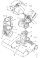
- In der Zeichnung ist ein Ausführungsbeispiel der Erfindung schematisch dargestellt. Es zeigen:
- Fig. 1
- einen Saugvorsatz mit Schwenkelement und aufgesetztem Drehelement als Anschlußvorrichtung,
- Fig. 2
- eine vergrößerte Darstellung einer Anschlußvorrichtung als schaubildliche Ansicht,
- Fig. 3
- eine Darstellung wie
Fig. 2 , mit zugeordnetem vergrößerten Ausschnitt einer Öffnung zum Einsetzen von Teilstücken - Fig. 4
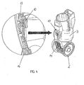
- eine Darstellung wie
Fig. 2 , mit zugeordnetem vergrößerten Ausschnitt der Verriegelung und - Fig. 5
- eine Darstellung einer Anordnung mit aufgesetztem Saugrohr
- Bei der dargestellten Anordnung ist ein üblicher Saugvorsatz (1) für ein Teppichreinigungsgerät vorgesehen der einen Sauganschluß in Form eine Schwenkelementes (2) aufweist. Auf das Schwenkelement (2) ist ein korrespondierendes übergreifendes Drehnelement (3) aufgesetzt, das gegenüber dem Schwenkelement (2) drehbar einstellbar ist. Das Schwenkelement (2) und das Drehelement (3) bilden einen Anschlußstutzen, in das ein Filtergehäuse mit seiner Handhabe über einen Stutzen in bekannter Weise einsetzbar ist.
- Eine Kopplung von Schwenkelement (2) und Drehelement (3) erfolgt jeweils über umlaufende, einander zugeordnete Nuten (4, 5) zur Aufnahme von einsetzbaren angepaßten Teilstücken (6) zur Bildung eines Führungs- und Halteringes (7). Die Teilelemente (6) werden dabei über eine Öffnung (8) im Drehelement (3) in die Nuten (4, 5) eingesetzt und die Öffnung (8) durch eine verriegelbare Abdeckung (9) verschlossen bzw. freigegeben.
- In einer vorbestimmten Mittelstellung des Drehelementes (3) und einer senkrechten Ausrichtung des Schwenkelementes (2) als definierte Ruhestellung greift eine im Schwenkelement (2) gelagerte, federbelastete Raste (10) in ein im Drehelement (3) angeordnetes Gegenlager (13) ein, um eine entsprechende Verriegelung der Drehbewegung in der Ruhestellung vorzunehmen und ein am Saugvorsatz (1) angeordnetes, mit dem Schwenkelement (2) korrespondierendes Verriegelungselement (12) dient der Verriegelung der Schwenkbewegung. Die Raste (10) wird dabei über einen nur in Ruhestellung, und damit senkrechter Ausrichtung des Schwenkelementes (2), mit dem Saugvorsatz (1) korrespondieren Schieber (14) betätigt. Zur Entriegelung des Schwenk- und Drehelementes (2, 3) wird das Verriegelungselement (12) betätigt und die Anordnung verschwenkt.
- Die federbelastete Raste (10) greift dabei in ein im Drehelement (3) angeordnetes Gegenlager (13) ein und wird bei Verschwenken des Drehelementes (3) wieder freigegeben.
Claims (12)
- Saugvorsatz für ein Bodenpflegegerät, insbesondere Staubsauger, zur verschwenkbaren und drehbeweglichen Verbindung über einen Anschluß des Saugvorsatzes (1) mit einem Sauganschluß und Handhabe des Bodenpflegegerätes, wobei ein Schwenkelement (2) am Saugvorsatz (1) schwenkbar angeordnet ist und mit einem korrespondierenden Drehelement (3), das einen Anschluß zum Bodenpflegegerät bildet, zur drehbeweglichen Verbindung gekoppelt ist sowie Schwenkelement (2) und Drehelement (3) ineinander greifen und im Verbindungsbereich von Schwenkelement (2) und Drehelement (3) über eine Nut (4) im Schwenkelement (2) und korrespondierende Elemente am Drehelement (3) eine Führung durchführbar ist, dadurch gekennzeichnet, daß jeweils umlaufende, einander zugeordnete Nuten (4, 5) am Schwenkelement (2) und Drehelement (3) zur Aufnahme von Teilstücken (6) und Ausbildung eines Führungs- und Halteringes (7) aufweisen, wobei die Teilstücke (6) über mindestens eine durch ein oder mehrere Verschlußelemente (9) abgedeckbare und/oder absperrbare Öffnung (8) im außen liegenden Element (2 oder 3) in die Nuten (4, 5) einsetzbar sind.
- Vorrichtung nach Anspruch 1, dadurch gekennzeichnet, daß das Drehelement (3) im Verbindungsbereich zum Schwenkelement (2) hülsenförmig über das Schwenkelement (2) greift.
- Vorrichtung nach Anspruch 1, dadurch gekennzeichnet, daß das Schwenkelement (2) im Verbindungsbereich zum Drehelement hülsenförmig über das Drehelement (3) greift.
- Vorrichtung nach einem der Ansprüche 1 bis 3, dadurch gekennzeichnet, daß eine der Nuten (4 oder 5) mindestens eine begrenzte taschenförmige Aufnahme zur Fixierung eines oder mehrerer Teilstücke (6) aufweist.
- Vorrichtung nach einem der Ansprüche 1 bis 4, dadurch gekennzeichnet, daß in einer vorbestimmten Mittelstellung des Drehelementes (3) und senkrechter Ausrichtung des Schwenkelementes (2) als Ruhestellung, eine im Schwenkelement (2) gelagerte federbelastete Raste (10) in ein im Drehelement (3) ausgebildetes Gegenlager (11) eingreift.
- Vorrichtung nach einem der Ansprüche 1 bis 5, dadurch gekennzeichnet, daß das Schwenkelement (2) über ein zugeordnetes verriegelungselement (12) gegen eine Abkippbewegung blockierbar ist.
- Vorrichtung nach Anspruch 6, dadurch gekennzeichnet, daß das Verriegelungselement durch eine fußbetätigte wippe (12) am Saugvorsatz (1) gebildet ist.
- Vorrichtung nach Anspruch 1, 2 oder 3, dadurch gekennzeichnet, daß ein Verschlußelement durch eine verriegelbare Abdeckung (9) am hülsenförmigen Element (3 bzw. 2) gebildet ist.
- Vorrichtung nach Anspruch 1 und 2 oder 3, dadurch gekennzeichnet, daß mindestens vier Teilstücke (6) zur Bildung eines Führungs- und Halteringes (7) in die Nuten (4, 5) von Schwenk- und Drehelement (2, 3) einsetzbar sind.
- Vorrichtung nach Anspruch 1 und 2 oder 3, dadurch gekennzeichnet, daß in und zwischen dem Schwenkelement (2) und Drehelement (3) ein taschenförmiger Zwischenraum zur beweglichen Aufnahme elektrischer Leiter ausgebildet ist.
- Vorrichtung nach einem der Ansprüche 1 bis 10, dadurch gekennzeichnet, daß das Drehelement (3) Bestandteil des Bodenpflegegerätes ist, das in der Verbindungsstelle zum Schwenkelement (2) an den Saugvorsatz (1) koppelbar ist.
- Vorrichtung nach Anspruch 1 bis 11, dadurch gekennzeichnet, daß der verbindungsbereich zwischen Schwenkelement (2) und Drehelement (3) zur Aufnahme der Nuten (4, 5) wulstartig ausgebildet ist.
Applications Claiming Priority (2)
| Application Number | Priority Date | Filing Date | Title |
|---|---|---|---|
| DE102004050471 | 2004-10-16 | ||
| DE102004052306A DE102004052306A1 (de) | 2004-10-16 | 2004-10-28 | Vorrichtung zur Anordnung eines Saugvorsatzes |
Publications (3)
| Publication Number | Publication Date |
|---|---|
| EP1647219A2 EP1647219A2 (de) | 2006-04-19 |
| EP1647219A3 EP1647219A3 (de) | 2007-03-14 |
| EP1647219B1 true EP1647219B1 (de) | 2008-07-23 |
Family
ID=35520541
Family Applications (1)
| Application Number | Title | Priority Date | Filing Date |
|---|---|---|---|
| EP05018243A Expired - Lifetime EP1647219B1 (de) | 2004-10-16 | 2005-08-23 | Saugvorsatz mit Kupplungsvorrichtung für Staubsauger |
Country Status (5)
| Country | Link |
|---|---|
| US (1) | US7503098B2 (de) |
| EP (1) | EP1647219B1 (de) |
| AT (1) | ATE401819T1 (de) |
| CA (1) | CA2523614C (de) |
| DE (2) | DE102004052306A1 (de) |
Cited By (9)
| Publication number | Priority date | Publication date | Assignee | Title |
|---|---|---|---|---|
| US8539636B2 (en) | 2009-10-15 | 2013-09-24 | Dyson Technology Limited | Surface treating appliance |
| US8650708B2 (en) | 2009-10-15 | 2014-02-18 | Dyson Technology Limited | Surface treating appliance |
| US8671511B2 (en) | 2009-10-15 | 2014-03-18 | Dyson Technology Limited | Surface treating appliance |
| US8677553B2 (en) | 2009-10-15 | 2014-03-25 | Dyson Technology Limited | Surface treating appliance |
| US8683647B2 (en) | 2009-10-15 | 2014-04-01 | Dyson Technology Limited | Surface treating appliance |
| US8793836B2 (en) | 2009-10-15 | 2014-08-05 | Dyson Technology Limited | Surface treating appliance |
| US8935826B2 (en) | 2009-10-15 | 2015-01-20 | Dyson Technology Limited | Surface treating appliance |
| US9009913B2 (en) | 2009-10-15 | 2015-04-21 | Dyson Technology Limited | Surface treating appliance |
| US9044129B2 (en) | 2009-10-15 | 2015-06-02 | Dyson Technology Limited | Surface treating appliance |
Families Citing this family (42)
| Publication number | Priority date | Publication date | Assignee | Title |
|---|---|---|---|---|
| US7979952B2 (en) | 2006-12-13 | 2011-07-19 | Ab Electrolux | Wet/dry floor cleaning device |
| DE102007040949A1 (de) | 2007-08-30 | 2009-03-05 | Miele & Cie. Kg | Upright-Staubsauger |
| DE102007040959A1 (de) | 2007-08-30 | 2009-03-05 | Miele & Cie. Kg | Upright-Staubsauger |
| DE102007040958A1 (de) | 2007-08-30 | 2009-03-05 | Miele & Cie. Kg | Upright-Staubsauger |
| DE102007040955A1 (de) | 2007-08-30 | 2009-03-05 | Miele & Cie. Kg | Upright-Staubsauger |
| DE102007040961A1 (de) | 2007-08-30 | 2009-03-05 | Miele & Cie. Kg | Upright-Staubsauger |
| GB2454921A (en) * | 2007-11-23 | 2009-05-27 | Dyson Technology Limited | Rotatable electrical connection for cleaner head |
| GB0806375D0 (en) * | 2008-04-08 | 2008-05-14 | Numatic Int Ltd | swivelling connection between members |
| CA2953105C (en) | 2009-07-30 | 2020-02-11 | Omachron Intellectual Property Inc. | Surface cleaning apparatus |
| CA2674763A1 (en) * | 2009-07-30 | 2011-01-30 | G.B.D. Corp. | Surface cleaning apparatus |
| GB2474468B (en) | 2009-10-15 | 2013-11-27 | Dyson Technology Ltd | A surface treating appliance |
| GB2474472B (en) | 2009-10-15 | 2013-10-23 | Dyson Technology Ltd | A surface treating appliance |
| GB2474471B (en) | 2009-10-15 | 2013-10-23 | Dyson Technology Ltd | A surface treating appliance |
| GB2474466B (en) * | 2009-10-15 | 2014-03-05 | Dyson Technology Ltd | A surface treating appliance |
| US8082624B2 (en) | 2009-11-10 | 2011-12-27 | Oreck Holdings Llc | Rotatable coupling for steering vacuum cleaner |
| US8667643B2 (en) | 2010-09-10 | 2014-03-11 | Euro-Pro Operating Llc | Method and apparatus for assisting pivot motion of a handle in a floor treatment device |
| JP5723017B2 (ja) | 2010-10-15 | 2015-05-27 | テクトロニック フロア ケア テクノロジー リミテッド | 表面クリーニング装置用ステアリングアッセンブリ |
| GB2485401B (en) | 2010-11-15 | 2015-04-01 | Hoover Ltd | Locking coupling for a vacuum cleaner |
| US8887352B2 (en) * | 2011-02-25 | 2014-11-18 | Panasonic Corporation Of North America | Canister vacuum cleaner incorporating a control handle and nozzle assembly with upright swivel lock |
| US9282862B2 (en) * | 2011-10-14 | 2016-03-15 | Techtronic Floor Care Technology Limited | Steering assembly for surface cleaning device |
| US10660494B1 (en) | 2011-10-31 | 2020-05-26 | James R. Alton | Vacuum cleaner |
| US10016107B2 (en) | 2011-12-14 | 2018-07-10 | Sharkninja Operating Llc | Surface cleaning apparatus with a sideways pivoting handle |
| US9060665B2 (en) | 2013-03-01 | 2015-06-23 | Euro-Pro Operating Llc | Floor cleaning appliance |
| US9962049B2 (en) | 2014-06-06 | 2018-05-08 | Sharkninja Operating Llc | Surface cleaning apparatus |
| USD762030S1 (en) | 2014-06-12 | 2016-07-19 | Sharkninja Operating Llc | Surface cleaning head for a vacuum cleaner |
| USD742089S1 (en) | 2014-06-27 | 2015-10-27 | Euro-Pro Operations LLC | Caddy |
| USD764125S1 (en) | 2014-06-30 | 2016-08-16 | Sharkninja Operating Llc | Duster |
| US9414725B2 (en) | 2014-12-05 | 2016-08-16 | Panasonic Corporation Of North America | Upright vacuum cleaner with two auxiliary operating modes |
| US10080471B2 (en) | 2015-12-21 | 2018-09-25 | Electrolux Home Care Products, Inc. | Versatile vacuum cleaners |
| US11058267B2 (en) | 2016-04-27 | 2021-07-13 | Aktiebolaget Electrolux | Vacuum cleaner and vacuum cleaner system |
| GB201616598D0 (en) * | 2016-09-30 | 2016-11-16 | Grey Technology Limited | Cleaning head for a vacuum cleaner |
| USD868406S1 (en) | 2017-07-25 | 2019-11-26 | Sharkninja Operating Llc | Vacuum cleaner tool |
| CA3076636C (en) | 2017-09-22 | 2021-10-12 | Sharkninja Operating Llc | Hand-held surface cleaning device |
| US11534042B2 (en) | 2017-12-15 | 2022-12-27 | Aktiebolaget Electrolux | Vacuum cleaner |
| USD873516S1 (en) | 2018-07-30 | 2020-01-21 | Sharkninja Operating Llc | Wand vacuum |
| CN114072032B (zh) | 2019-05-01 | 2023-04-14 | 尚科宁家运营有限公司 | 真空清洁器以及与真空清洁器一起使用的对接站 |
| WO2022011079A1 (en) | 2020-07-09 | 2022-01-13 | Milwaukee Electric Tool Corporation | Floor tool attachment for use with vacuum cleaner |
| USD995020S1 (en) | 2020-07-29 | 2023-08-08 | Sharkninja Operating Llc | Vacuum cleaner docking station |
| USD995019S1 (en) | 2020-07-29 | 2023-08-08 | Sharkninja Operating Llc | Vacuum cleaner |
| USD995016S1 (en) | 2020-07-29 | 2023-08-08 | Sharkninja Operating Llc | Vacuum cleaner |
| US12419475B2 (en) | 2021-11-03 | 2025-09-23 | Techtronic Cordless Gp | Vacuum cleaner |
| KR20230086156A (ko) * | 2021-12-08 | 2023-06-15 | 엘지전자 주식회사 | 청소기 |
Family Cites Families (5)
| Publication number | Priority date | Publication date | Assignee | Title |
|---|---|---|---|---|
| NL294109A (de) * | 1962-06-15 | |||
| US6055703A (en) * | 1997-10-14 | 2000-05-02 | Oreck Holdings Llc | Upright vacuum cleaner having improved steering apparatus with a lock out feature |
| JP3642939B2 (ja) * | 1998-01-20 | 2005-04-27 | 東芝テック株式会社 | 吸込口体及びこれを用いた電気掃除機 |
| FR2827755B1 (fr) * | 2001-07-26 | 2003-10-03 | Wessel Werk Gmbh | Suceur pour aspirateur-traineau |
| JP4079788B2 (ja) * | 2003-01-31 | 2008-04-23 | 株式会社東芝 | 吸込口体及びこれを備える電気掃除機 |
-
2004
- 2004-10-28 DE DE102004052306A patent/DE102004052306A1/de not_active Withdrawn
-
2005
- 2005-08-23 DE DE502005004787T patent/DE502005004787D1/de not_active Expired - Lifetime
- 2005-08-23 AT AT05018243T patent/ATE401819T1/de active
- 2005-08-23 EP EP05018243A patent/EP1647219B1/de not_active Expired - Lifetime
- 2005-10-17 CA CA2523614A patent/CA2523614C/en not_active Expired - Lifetime
- 2005-10-17 US US11/253,158 patent/US7503098B2/en active Active
Cited By (10)
| Publication number | Priority date | Publication date | Assignee | Title |
|---|---|---|---|---|
| US8539636B2 (en) | 2009-10-15 | 2013-09-24 | Dyson Technology Limited | Surface treating appliance |
| US8650708B2 (en) | 2009-10-15 | 2014-02-18 | Dyson Technology Limited | Surface treating appliance |
| US8671511B2 (en) | 2009-10-15 | 2014-03-18 | Dyson Technology Limited | Surface treating appliance |
| US8677553B2 (en) | 2009-10-15 | 2014-03-25 | Dyson Technology Limited | Surface treating appliance |
| US8683647B2 (en) | 2009-10-15 | 2014-04-01 | Dyson Technology Limited | Surface treating appliance |
| US8793836B2 (en) | 2009-10-15 | 2014-08-05 | Dyson Technology Limited | Surface treating appliance |
| US8935826B2 (en) | 2009-10-15 | 2015-01-20 | Dyson Technology Limited | Surface treating appliance |
| US9009913B2 (en) | 2009-10-15 | 2015-04-21 | Dyson Technology Limited | Surface treating appliance |
| US9044129B2 (en) | 2009-10-15 | 2015-06-02 | Dyson Technology Limited | Surface treating appliance |
| US9247853B2 (en) | 2009-10-15 | 2016-02-02 | Dyson Technology Limited | Surface treating appliance |
Also Published As
| Publication number | Publication date |
|---|---|
| US7503098B2 (en) | 2009-03-17 |
| ATE401819T1 (de) | 2008-08-15 |
| EP1647219A2 (de) | 2006-04-19 |
| CA2523614C (en) | 2013-07-16 |
| DE102004052306A1 (de) | 2006-04-20 |
| DE502005004787D1 (de) | 2008-09-04 |
| EP1647219A3 (de) | 2007-03-14 |
| CA2523614A1 (en) | 2006-04-16 |
| US20060080803A1 (en) | 2006-04-20 |
Similar Documents
| Publication | Publication Date | Title |
|---|---|---|
| EP1647219A2 (de) | Vorrichtung zur Anordnung eines Saugvorsatzes | |
| DE102019217532A1 (de) | Kettlebell | |
| EP1639932A2 (de) | Vorrichtung für Bürstenwalze von Bodenpflegegeräten | |
| DE10296326T5 (de) | Luftausströmer, insbesondere eines Kraftfahrzeuges | |
| EP0406566B1 (de) | Drehhandhabe | |
| EP3576126A1 (de) | Schutzschalter-sperrvorrichtung | |
| DE102013112570B4 (de) | Vorrichtung zum Betätigen eines in einem Schaltschrank befindlichen Schaltgeräts | |
| DE202020100370U1 (de) | Sonnenschirm unter Verwendung einer Struktur ohne Griffgehäuse | |
| DE102021105288B4 (de) | Leicht umkehrbare Umschaltknarre | |
| EP1862613A1 (de) | Vorrichtung zur Betätigung von Fenstern | |
| EP1528194A1 (de) | Beschlag, insbesondere Fensterbeschlag | |
| DE60103880T2 (de) | Einsenkbares abdeckungsystem zur maskierung einer vorrichtung, insbesondere für eine elektrische steckdose, und zugehöriges elektrisches gerät | |
| DE60106130T2 (de) | Verschlussvorrichtung für elektrischen Kasten | |
| DE3807168C2 (de) | Beweglicher Anschlußstutzen für Staubsaugerzubehör | |
| EP2594180A2 (de) | Reinigungsgerät, insbesondere Staubsauger | |
| DE102017009817A1 (de) | Verschließeinrichtung und -mechanismus insbesondere zur Sicherung von flächigen, zweigliedrigen Verbindungshalterungen (z.B. Schubverschlüssen) | |
| DE10332394B4 (de) | Verriegelungssystem für zwei Spielhälften eines Tischtennisspieles | |
| DE19745019B4 (de) | Elektrisches Installationsgerät wie Schalter oder Taster | |
| EP3771380A1 (de) | Sicherungsverschluss für ein gefäss einer küchenmaschine, gefäss mit sicherungsverschluss und küchenmaschine | |
| EP3990738A1 (de) | Gehäuse für einen antrieb sowie antrieb | |
| EP2067152B1 (de) | Sicherungs-lasttrennschalter mit absperrvorrichtung | |
| DE3725430C1 (en) | Storm bar for a hood of a pram/push-chair | |
| DE19847017C1 (de) | Clipverriegelung mittels Spreizdübelverschluß für tragbaren Telefonapparat | |
| DE3743844A1 (de) | Steckdose mit einem schwenkbaren deckel | |
| DE102018100383A1 (de) | Drehmomentschraubenzieher |
Legal Events
| Date | Code | Title | Description |
|---|---|---|---|
| PUAI | Public reference made under article 153(3) epc to a published international application that has entered the european phase |
Free format text: ORIGINAL CODE: 0009012 |
|
| AK | Designated contracting states |
Kind code of ref document: A2 Designated state(s): AT BE BG CH CY CZ DE DK EE ES FI FR GB GR HU IE IS IT LI LT LU LV MC NL PL PT RO SE SI SK TR |
|
| AX | Request for extension of the european patent |
Extension state: AL BA HR MK YU |
|
| PUAL | Search report despatched |
Free format text: ORIGINAL CODE: 0009013 |
|
| AK | Designated contracting states |
Kind code of ref document: A3 Designated state(s): AT BE BG CH CY CZ DE DK EE ES FI FR GB GR HU IE IS IT LI LT LU LV MC NL PL PT RO SE SI SK TR |
|
| AX | Request for extension of the european patent |
Extension state: AL BA HR MK YU |
|
| 17P | Request for examination filed |
Effective date: 20070328 |
|
| AKX | Designation fees paid |
Designated state(s): AT BE BG CH CY CZ DE DK EE ES FI FR GB GR HU IE IS IT LI LT LU LV MC NL PL PT RO SE SI SK TR |
|
| GRAP | Despatch of communication of intention to grant a patent |
Free format text: ORIGINAL CODE: EPIDOSNIGR1 |
|
| RTI1 | Title (correction) |
Free format text: SUCTION NOZZLE COUPLIG DEVICE FOR VACUUM CLEANER |
|
| GRAS | Grant fee paid |
Free format text: ORIGINAL CODE: EPIDOSNIGR3 |
|
| GRAA | (expected) grant |
Free format text: ORIGINAL CODE: 0009210 |
|
| AK | Designated contracting states |
Kind code of ref document: B1 Designated state(s): AT BE BG CH CY CZ DE DK EE ES FI FR GB GR HU IE IS IT LI LT LU LV MC NL PL PT RO SE SI SK TR |
|
| REG | Reference to a national code |
Ref country code: GB Ref legal event code: FG4D Free format text: NOT ENGLISH |
|
| REG | Reference to a national code |
Ref country code: CH Ref legal event code: EP |
|
| REG | Reference to a national code |
Ref country code: IE Ref legal event code: FG4D Free format text: LANGUAGE OF EP DOCUMENT: GERMAN |
|
| REF | Corresponds to: |
Ref document number: 502005004787 Country of ref document: DE Date of ref document: 20080904 Kind code of ref document: P |
|
| PG25 | Lapsed in a contracting state [announced via postgrant information from national office to epo] |
Ref country code: LT Free format text: LAPSE BECAUSE OF FAILURE TO SUBMIT A TRANSLATION OF THE DESCRIPTION OR TO PAY THE FEE WITHIN THE PRESCRIBED TIME-LIMIT Effective date: 20080723 Ref country code: PT Free format text: LAPSE BECAUSE OF FAILURE TO SUBMIT A TRANSLATION OF THE DESCRIPTION OR TO PAY THE FEE WITHIN THE PRESCRIBED TIME-LIMIT Effective date: 20081223 Ref country code: IS Free format text: LAPSE BECAUSE OF FAILURE TO SUBMIT A TRANSLATION OF THE DESCRIPTION OR TO PAY THE FEE WITHIN THE PRESCRIBED TIME-LIMIT Effective date: 20081123 Ref country code: ES Free format text: LAPSE BECAUSE OF FAILURE TO SUBMIT A TRANSLATION OF THE DESCRIPTION OR TO PAY THE FEE WITHIN THE PRESCRIBED TIME-LIMIT Effective date: 20081103 |
|
| PG25 | Lapsed in a contracting state [announced via postgrant information from national office to epo] |
Ref country code: SI Free format text: LAPSE BECAUSE OF FAILURE TO SUBMIT A TRANSLATION OF THE DESCRIPTION OR TO PAY THE FEE WITHIN THE PRESCRIBED TIME-LIMIT Effective date: 20080723 Ref country code: FI Free format text: LAPSE BECAUSE OF FAILURE TO SUBMIT A TRANSLATION OF THE DESCRIPTION OR TO PAY THE FEE WITHIN THE PRESCRIBED TIME-LIMIT Effective date: 20080723 Ref country code: BG Free format text: LAPSE BECAUSE OF FAILURE TO SUBMIT A TRANSLATION OF THE DESCRIPTION OR TO PAY THE FEE WITHIN THE PRESCRIBED TIME-LIMIT Effective date: 20081023 Ref country code: LV Free format text: LAPSE BECAUSE OF FAILURE TO SUBMIT A TRANSLATION OF THE DESCRIPTION OR TO PAY THE FEE WITHIN THE PRESCRIBED TIME-LIMIT Effective date: 20080723 |
|
| REG | Reference to a national code |
Ref country code: IE Ref legal event code: FD4D |
|
| PG25 | Lapsed in a contracting state [announced via postgrant information from national office to epo] |
Ref country code: MC Free format text: LAPSE BECAUSE OF NON-PAYMENT OF DUE FEES Effective date: 20080831 |
|
| PG25 | Lapsed in a contracting state [announced via postgrant information from national office to epo] |
Ref country code: DK Free format text: LAPSE BECAUSE OF FAILURE TO SUBMIT A TRANSLATION OF THE DESCRIPTION OR TO PAY THE FEE WITHIN THE PRESCRIBED TIME-LIMIT Effective date: 20080723 Ref country code: IE Free format text: LAPSE BECAUSE OF FAILURE TO SUBMIT A TRANSLATION OF THE DESCRIPTION OR TO PAY THE FEE WITHIN THE PRESCRIBED TIME-LIMIT Effective date: 20080723 Ref country code: EE Free format text: LAPSE BECAUSE OF FAILURE TO SUBMIT A TRANSLATION OF THE DESCRIPTION OR TO PAY THE FEE WITHIN THE PRESCRIBED TIME-LIMIT Effective date: 20080723 |
|
| PG25 | Lapsed in a contracting state [announced via postgrant information from national office to epo] |
Ref country code: CZ Free format text: LAPSE BECAUSE OF FAILURE TO SUBMIT A TRANSLATION OF THE DESCRIPTION OR TO PAY THE FEE WITHIN THE PRESCRIBED TIME-LIMIT Effective date: 20080723 Ref country code: RO Free format text: LAPSE BECAUSE OF FAILURE TO SUBMIT A TRANSLATION OF THE DESCRIPTION OR TO PAY THE FEE WITHIN THE PRESCRIBED TIME-LIMIT Effective date: 20080723 Ref country code: SK Free format text: LAPSE BECAUSE OF FAILURE TO SUBMIT A TRANSLATION OF THE DESCRIPTION OR TO PAY THE FEE WITHIN THE PRESCRIBED TIME-LIMIT Effective date: 20080723 |
|
| PLBE | No opposition filed within time limit |
Free format text: ORIGINAL CODE: 0009261 |
|
| STAA | Information on the status of an ep patent application or granted ep patent |
Free format text: STATUS: NO OPPOSITION FILED WITHIN TIME LIMIT |
|
| 26N | No opposition filed |
Effective date: 20090424 |
|
| REG | Reference to a national code |
Ref country code: FR Ref legal event code: ST Effective date: 20090630 |
|
| PG25 | Lapsed in a contracting state [announced via postgrant information from national office to epo] |
Ref country code: BE Free format text: LAPSE BECAUSE OF NON-PAYMENT OF DUE FEES Effective date: 20080831 |
|
| REG | Reference to a national code |
Ref country code: FR Ref legal event code: RN |
|
| PG25 | Lapsed in a contracting state [announced via postgrant information from national office to epo] |
Ref country code: FR Free format text: LAPSE BECAUSE OF NON-PAYMENT OF DUE FEES Effective date: 20080901 |
|
| REG | Reference to a national code |
Ref country code: FR Ref legal event code: FC |
|
| PG25 | Lapsed in a contracting state [announced via postgrant information from national office to epo] |
Ref country code: SE Free format text: LAPSE BECAUSE OF FAILURE TO SUBMIT A TRANSLATION OF THE DESCRIPTION OR TO PAY THE FEE WITHIN THE PRESCRIBED TIME-LIMIT Effective date: 20081023 |
|
| REG | Reference to a national code |
Ref country code: CH Ref legal event code: PL |
|
| PG25 | Lapsed in a contracting state [announced via postgrant information from national office to epo] |
Ref country code: LI Free format text: LAPSE BECAUSE OF NON-PAYMENT OF DUE FEES Effective date: 20090831 Ref country code: CH Free format text: LAPSE BECAUSE OF NON-PAYMENT OF DUE FEES Effective date: 20090831 |
|
| PGRI | Patent reinstated in contracting state [announced from national office to epo] |
Ref country code: FR Effective date: 20100125 |
|
| PG25 | Lapsed in a contracting state [announced via postgrant information from national office to epo] |
Ref country code: PL Free format text: LAPSE BECAUSE OF FAILURE TO SUBMIT A TRANSLATION OF THE DESCRIPTION OR TO PAY THE FEE WITHIN THE PRESCRIBED TIME-LIMIT Effective date: 20080723 |
|
| PG25 | Lapsed in a contracting state [announced via postgrant information from national office to epo] |
Ref country code: LU Free format text: LAPSE BECAUSE OF NON-PAYMENT OF DUE FEES Effective date: 20080823 Ref country code: HU Free format text: LAPSE BECAUSE OF FAILURE TO SUBMIT A TRANSLATION OF THE DESCRIPTION OR TO PAY THE FEE WITHIN THE PRESCRIBED TIME-LIMIT Effective date: 20090124 Ref country code: CY Free format text: LAPSE BECAUSE OF FAILURE TO SUBMIT A TRANSLATION OF THE DESCRIPTION OR TO PAY THE FEE WITHIN THE PRESCRIBED TIME-LIMIT Effective date: 20080723 |
|
| PG25 | Lapsed in a contracting state [announced via postgrant information from national office to epo] |
Ref country code: TR Free format text: LAPSE BECAUSE OF FAILURE TO SUBMIT A TRANSLATION OF THE DESCRIPTION OR TO PAY THE FEE WITHIN THE PRESCRIBED TIME-LIMIT Effective date: 20080723 |
|
| PG25 | Lapsed in a contracting state [announced via postgrant information from national office to epo] |
Ref country code: GR Free format text: LAPSE BECAUSE OF FAILURE TO SUBMIT A TRANSLATION OF THE DESCRIPTION OR TO PAY THE FEE WITHIN THE PRESCRIBED TIME-LIMIT Effective date: 20081024 |
|
| PGFP | Annual fee paid to national office [announced via postgrant information from national office to epo] |
Ref country code: NL Payment date: 20140829 Year of fee payment: 10 |
|
| PGFP | Annual fee paid to national office [announced via postgrant information from national office to epo] |
Ref country code: AT Payment date: 20140829 Year of fee payment: 10 |
|
| REG | Reference to a national code |
Ref country code: DE Ref legal event code: R082 Ref document number: 502005004787 Country of ref document: DE Representative=s name: ELBPATENT - MARSCHALL & PARTNER PARTGMBB, DE |
|
| REG | Reference to a national code |
Ref country code: AT Ref legal event code: MM01 Ref document number: 401819 Country of ref document: AT Kind code of ref document: T Effective date: 20150823 |
|
| REG | Reference to a national code |
Ref country code: NL Ref legal event code: MM Effective date: 20150901 |
|
| PG25 | Lapsed in a contracting state [announced via postgrant information from national office to epo] |
Ref country code: AT Free format text: LAPSE BECAUSE OF NON-PAYMENT OF DUE FEES Effective date: 20150823 |
|
| PG25 | Lapsed in a contracting state [announced via postgrant information from national office to epo] |
Ref country code: NL Free format text: LAPSE BECAUSE OF NON-PAYMENT OF DUE FEES Effective date: 20150901 |
|
| REG | Reference to a national code |
Ref country code: FR Ref legal event code: PLFP Year of fee payment: 12 |
|
| PGFP | Annual fee paid to national office [announced via postgrant information from national office to epo] |
Ref country code: FR Payment date: 20160825 Year of fee payment: 12 |
|
| REG | Reference to a national code |
Ref country code: FR Ref legal event code: ST Effective date: 20180430 |
|
| PG25 | Lapsed in a contracting state [announced via postgrant information from national office to epo] |
Ref country code: FR Free format text: LAPSE BECAUSE OF NON-PAYMENT OF DUE FEES Effective date: 20170831 |
|
| PGFP | Annual fee paid to national office [announced via postgrant information from national office to epo] |
Ref country code: IT Payment date: 20200826 Year of fee payment: 16 |
|
| PG25 | Lapsed in a contracting state [announced via postgrant information from national office to epo] |
Ref country code: IT Free format text: LAPSE BECAUSE OF NON-PAYMENT OF DUE FEES Effective date: 20210823 |
|
| PGFP | Annual fee paid to national office [announced via postgrant information from national office to epo] |
Ref country code: DE Payment date: 20220720 Year of fee payment: 18 |
|
| P01 | Opt-out of the competence of the unified patent court (upc) registered |
Effective date: 20230527 |
|
| PGFP | Annual fee paid to national office [announced via postgrant information from national office to epo] |
Ref country code: GB Payment date: 20230822 Year of fee payment: 19 |
|
| REG | Reference to a national code |
Ref country code: DE Ref legal event code: R119 Ref document number: 502005004787 Country of ref document: DE |
|
| PG25 | Lapsed in a contracting state [announced via postgrant information from national office to epo] |
Ref country code: DE Free format text: LAPSE BECAUSE OF NON-PAYMENT OF DUE FEES Effective date: 20240301 |
|
| GBPC | Gb: european patent ceased through non-payment of renewal fee |
Effective date: 20240823 |
|
| PG25 | Lapsed in a contracting state [announced via postgrant information from national office to epo] |
Ref country code: GB Free format text: LAPSE BECAUSE OF NON-PAYMENT OF DUE FEES Effective date: 20240823 |