EP1645707B1 - Laufwagenanordnung für schwere Abstellschiebeflügel - Google Patents
Laufwagenanordnung für schwere Abstellschiebeflügel Download PDFInfo
- Publication number
- EP1645707B1 EP1645707B1 EP04104920.6A EP04104920A EP1645707B1 EP 1645707 B1 EP1645707 B1 EP 1645707B1 EP 04104920 A EP04104920 A EP 04104920A EP 1645707 B1 EP1645707 B1 EP 1645707B1
- Authority
- EP
- European Patent Office
- Prior art keywords
- carriage
- wing
- arrangement according
- pair
- carriage arrangement
- Prior art date
- Legal status (The legal status is an assumption and is not a legal conclusion. Google has not performed a legal analysis and makes no representation as to the accuracy of the status listed.)
- Expired - Lifetime
Links
- 230000008878 coupling Effects 0.000 claims description 2
- 238000010168 coupling process Methods 0.000 claims description 2
- 238000005859 coupling reaction Methods 0.000 claims description 2
- 230000000694 effects Effects 0.000 claims description 2
- 238000005452 bending Methods 0.000 description 1
- 230000005540 biological transmission Effects 0.000 description 1
- 230000001419 dependent effect Effects 0.000 description 1
- 238000006073 displacement reaction Methods 0.000 description 1
- 238000009434 installation Methods 0.000 description 1
Images


Classifications
-
- E—FIXED CONSTRUCTIONS
- E05—LOCKS; KEYS; WINDOW OR DOOR FITTINGS; SAFES
- E05D—HINGES OR SUSPENSION DEVICES FOR DOORS, WINDOWS OR WINGS
- E05D15/00—Suspension arrangements for wings
- E05D15/06—Suspension arrangements for wings for wings sliding horizontally more or less in their own plane
- E05D15/10—Suspension arrangements for wings for wings sliding horizontally more or less in their own plane movable out of one plane into a second parallel plane
- E05D15/1005—Suspension arrangements for wings for wings sliding horizontally more or less in their own plane movable out of one plane into a second parallel plane the wing being supported on arms movable in horizontal planes
-
- E—FIXED CONSTRUCTIONS
- E05—LOCKS; KEYS; WINDOW OR DOOR FITTINGS; SAFES
- E05Y—INDEXING SCHEME ASSOCIATED WITH SUBCLASSES E05D AND E05F, RELATING TO CONSTRUCTION ELEMENTS, ELECTRIC CONTROL, POWER SUPPLY, POWER SIGNAL OR TRANSMISSION, USER INTERFACES, MOUNTING OR COUPLING, DETAILS, ACCESSORIES, AUXILIARY OPERATIONS NOT OTHERWISE PROVIDED FOR, APPLICATION THEREOF
- E05Y2201/00—Constructional elements; Accessories therefor
- E05Y2201/60—Suspension or transmission members; Accessories therefor
- E05Y2201/622—Suspension or transmission members elements
- E05Y2201/686—Rods, links
Definitions
- the invention relates to a carriage arrangement for a heavy AbstellSchiebeeriel a window or a door according to the preamble of claim 1. It is basically already known, for example from the EP-A 1 170 448 A1 to provide for supporting such a heavy wing more than two carriages, each carriage part is connected via a Abstellarm with a wing-side mounting part, while the successive car parts, as usual, each coupled via a rod-shaped round profile.
- the invention has for its object to enable a reliable transmission of large sash weights on the track with simple means. It should also be achieved that regardless of the attack situation (right or left-stopability) each carriage assembly can be composed of relatively few parts.
- a carriage arrangement for a heavy AbstellSchiebeeriel a window or a door with the features of claim 1. Further details and advantageous embodiments will become apparent from the other claims.
- a common, the wing frame mountable elongated rail with articulation points for the two Abstellarme each pair of carriages is provided, wherein the rail has at its two ends in each case a receiving bore into which can be inserted and attached to a lower wing spar when mounting a vertical strut.
- the large sash weight is absorbed by at least two mountable on the casement elongated rails and over the two articulation points each rail and associated Abstellarmen evenly and without bending of the lower spar of the wing securely placed on the at least four carriages of the carriage assembly.
- This wing weights up to 200 kg and clearly above can be safely absorbed and placed on the track of the carriage assembly.
- that one pair of carriages which is closest to the wing side with the operating handle has two identically designed carriage housings, while the other pair of carriages has a carriage housing which relative to a plane perpendicular to the sliding direction is formed in mirror image to the carriage housing of the other pair of carriages.
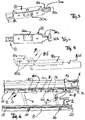
- FIGS. 1 and 2 are each in FIG. 1a respectively.
- FIG. 2a the two pairs of carriages in their respective stop position shown in perspective, while the Figures 1b and 2 B shows the associated stop position by a plan view of a corresponding window assembly.
- the carriage pair A has two carriages 4 and 5 (with housing), which are similar to each other, but also differ, while the two carriages 30 and 31 (with housing) of the carriage pair B are identical. Details for the pair of carriages B can be the FIGS. 3 to 5 remove.
- FIGS. 3 and 4 shows the associated carriage housing 30 (or 31), which has in its central region an opening 30a, in which the one end of the Abstellarme 6.7 inserted and articulated there is connected to the housing. At its one end, the housing 30 and 31, a connection sleeve 12 into which the one end of a connecting rod 13 can be inserted and secured therein.
- the housing has a rivet or mounting plateau 30b, on which rivet heads 30c are provided in the example shown, in order to be able to connect the housing to a connecting part, which connecting part in FIG FIG. 5 is shown in perspective.
- the connecting part 10 may be a cast part, but is made in the preferred example shown as a stamped and bent part.
- the link 10 has a round rod portion 10d, preferably welded to the plate portion 10e, which can be received in the coupling sleeve 12 of an adjacent carriage 31 and fixed therein.
- the connecting member has a flat connecting and mounting portion 10 a, which has two rivet openings 10 b in the example shown and can be riveted to the mounting portion 30 b of the housing 30.
- the bent part has a crank 10f, which leads into the flat plate portion 10e.
- FIGS. 1a . 2a and 6 are shown connecting member 10 and the adjacent two housing parts in the assembled state.
- the mounting portion 30b is used at the side of the wing 2, on which the operating handle 29 is arranged next lying carriage housing for attaching the plate-shaped control member 9a serving for pressing or pressing the blade control device.
- FIG. 1a one recognizes that the housing of the carriage 5 of the pair of carriages A - with respect to a plane perpendicular to the direction of displacement of the wing - mirror images of the housings of the carriage 30 and 31 is formed, so apart from the mirroring is the same as that in the FIGS. 3 and 4 shown carriage housing 30.
- the connecting members 10 can, as well as FIG. 1a already shows, to be used oriented in both possible sliding directions.
- carriage housings 30 and 31 are identical, the carriage housing 5 is the same but mirror-inverted, while the carriage housing 4, which is farthest from the wing side, at which the handle 29 differs from both in that it has at one end instead of the flat mounting portion a stop or buffer 4a, which comes into effect on reaching the full open position.
- the control part as a plate 9a of the control device 9 has a control slot for a sliding pin of a control arm, which is articulated at 9e.
- the carriage housing 36 is identical to the carriage housings 30 and 31, and the same could apply to the housing 37 when the buffer or abutment part 37a as a separate part to the flat mounting portion of such a car is mounted.
- the carriage arrangement is independent of the stop position with four different types of housing, while it would be in the case of the separate buffer, not shown, even only two types of carriage housings.
- the connecting members 10 are formed the same. The same applies to the two Abstellarme 6, 7 each pair of carriages. These can be used for both applications, with the Abstellarme must be turned by 180 °.
- Each pair of arms 6, 7 of a pair of carriages is hingedly mounted on the wing side on an elongate common rail 8.
- the mounting locations are designated 26.
- two different rails 8 and 8a are required for the different types of installation (right / left), as a comparison of FIGS. 1a and 2a shows.
- each of the carriage pairs has only one common mounting rail. It can be seen that the high sash weight initially deposited on the elongated two rails and from there can be safely transferred to the respective two pivot points 26 of the Abstellarme 6 and 7.
- a deflection of the lower wing spar due to only a punctiform connection of carriage with wing spar is excluded.
- the wing-side mounting rail has at its two ends in each case a receiving bore 25a into which a vertical strut can be inserted and fixed in the vertical wing spar when mounting.
- These bores 25 and 25a are provided at both ends of each of the mounting rails 8 and 8a, respectively.
- Each carriage housing has a pair of rollers.
- the carriage arrangement proves to be extremely stable and stable and is very simple and composed of few parts, the individual parts are designed extremely robust. This applies both to the carriage arrangement itself and to the connecting areas to the lower spar of the wing. Deformations of the wing under its high weight are safely avoided by the elongated rails 8,8a.
Landscapes
- Engineering & Computer Science (AREA)
- Mechanical Engineering (AREA)
- Wing Frames And Configurations (AREA)
Description
- Die Erfindung betrifft eine Laufwagen-Anordnung für einen schweren AbstellSchiebeflügel eines Fensters oder einer Tür nach dem Oberbegriff des Anspruches 1.
Es ist grundsätzlich bereits bekannt, zum Beispiel aus derEP-A 1 170 448 A1
Der Erfindung liegt die Aufgabe zugrunde, eine zuverlässige Übertragung großer Flügelgewichte auf die Laufschiene mit einfachen Mitteln zu ermöglichen. Es soll außerdem erreicht werden, dass unabhängig von der Anschlagssituation (Rechts- oder Links-Anschlagbarkeit) jede Laufwagen-Anordnung aus relativ wenigen Teilen zusammengesetzt werden kann.
Diese Aufgabe wird mit einer Laufwagen-Anordnung für einen schweren AbstellSchiebeflügel eines Fensters oder einer Tür mit den Merkmalen des Anspruches 1 gelöst.
Weitere Einzelheiten und vorteilhafte Ausbildungen ergeben sich aus den weiteren Ansprüchen.
Erfindungsgemäß ist eine gemeinsame, am Flügelrahmen montierbare langgestreckte Profilschiene mit Anlenkstellen für die beiden Abstellarme jedes Laufwagen-Paares vorgesehen, wobei die Profilschiene an ihren beiden Enden jeweils eine Aufnahmebohrung aufweist, in die beim Montieren eine Vertikalstrebe an einem unteren Flügelholm eingesteckt und befestigt werden kann. Hierbei wird das große Flügelgewicht durch zumindest zwei am Flügelrahmen montierbare langgestreckte Profilschienen aufgenommen und über die beiden Anlenkstellen jeder Profilschiene und diesen zugeordneten Abstellarmen gleichmäßig und ohne Durchbiegen des unteren Holms des Flügels sicher auf die wenigstens vier Laufwagen der Laufwagen-Anordnung abgesetzt wird. Damit können Flügelgewichte bis zu 200 kg und deutlich darüber sicher aufgenommen und auf die Laufschiene der Laufwagen-Anordnung abgesetzt werden.
Vorzugsweise weist dasjenige Laufwagen-Paar, welches der Flügelseite mit dem Betätigungsgriff am nächsten ist, zwei identisch ausgebildete Laufwagengehäuse auf, während das andere Laufwagen-Paar ein Laufwagen-Gehäuse aufweist, das bezogen auf eine Ebene senkrecht zur Schieberichtung spiegelbildlich zu dem Laufwagengehäuse des anderen Laufwagenpaares ausgebildet ist. - Dabei ist die ganze Anordnung außerordentlich einfach, da unabhängig von der linksseitigen oder rechtsseitigen Anschlagart für jeweils drei Positionen der Anordnung identische Laufwagengehäuse eingesetzt werden können. Im günstigsten Fall können beide Einsatzmöglichkeiten lediglich mit einem Satz von vier verschiedenen Laufwagen-Gehäusen abgedeckt werden.
- Weitere Einzelheiten und vorteilhafte Ausbildungen ergeben sich aus den abhängigen Ansprüchen.
- Die Erfindung wird nachfolgend anhand von Ausführungsbeispielen erläutert und ergänzt.
- Figur la, Figur 1b, Figur 2a, Figur 2b
- zeigen jeweils in gleicher Darstellung eine Laufwagen-Anordnung, und zwar in den
Figuren 1 für nach links zu öffnende Schiebeflügel 2 und in denFiguren 2 für nach rechts öffnende Schiebeflügel 2. - Figur 3, Figur 4
- zeigen ein Laufwagen-Gehäuse 30, in perspektivischer Ansicht und in Seitenansicht.
- Figur 5
- zeigt in perspektivischer Ansicht ein Verbindungselement 10, das zwischen den Laufwagen-Gehäusen eines Laufwagen-Paares eingesetzt werden kann.
- Figur 6
- zeigt eines der in
Figuren 1 dargestellten Laufwagen-Paare bei geöffnetem Flügel in Aufsicht. - In den
Figuren 1 und2 sind jeweils inFigur 1a bzw.Figur 2a die beiden Laufwagen-Paare in ihrer jeweiligen Anschlagposition in perspektivischer Darstellung gezeigt, während dieFiguren 1b und2b die zugehörige Anschlagposition durch eine Draufsicht auf eine entsprechende Fensteranordnung zeigt. - In der Anordnung für nach links zu öffnende Flügel 2 gemäß
Figur 1 sind zwei Laufwagen-Paare A und B auf einer gemeinsamen (nicht gezeigten) Laufschiene angeordnet und über eine Verbindungsstange 13, vorzugsweise mit Rundprofil, miteinander verbunden. - Das Laufwagen-Paar A weist zwei Laufwagen 4 und 5 (mit Gehäuse) auf, die zwar einander ähnlich ausgebildet sind, sich jedoch auch unterscheiden, während die beiden Laufwagen 30 und 31 (mit Gehäuse) des Laufwagen-Paares B identisch ausgebildet sind.
Einzelheiten für das Laufwagen-Paar B lassen sich denFiguren 3 bis 5 entnehmen.
Figur 3 und 4 zeigt das zugehörige Laufwagen-Gehäuse 30 (oder 31), das in seinem Mittenbereich eine Öffnung 30a aufweist, in die das eine Ende der Abstellarme 6,7 eingefügt und dort gelenkig mit dem Gehäuse verbunden wird. An seinem einen Ende weist das Gehäuse 30 bzw. 31 eine Verbindungsmuffe 12 auf, in die das eine Ende einer Verbindungsstange 13 eingeschoben und darin befestigt werden kann. Am anderen Ende weist das Gehäuse ein Niet- oder Montageplateau 30b auf, an dem im dargestellten Beispiel Nietköpfe 30c vorgesehen sind, um das Gehäuse mit einem Verbindungsteil verbinden zu können, welches Verbindungsteil inFigur 5 perspektivisch dargestellt ist.
Das Verbindungsteil 10 kann ein Gussteil sein, ist jedoch in dem gezeigten bevorzugten Beispiel als Stanzbiegeteil angefertigt. An seinem einen Ende weist das Verbindungsglied 10 einen an dem Plattenabschnitt 10e vorzugsweise angeschweißten Rundstangenabschnitt 10d auf, der in der Verbindungsmuffe 12 eines benachbarten Laufwagens 31 aufgenommen und darin befestigt werden kann. Am anderen Ende weist das Verbindungsglied einen flachen Verbindungs- und Montageabschnitt 10a auf, der im dargestellten Beispiel zwei Nietöffnungen 10b besitzt und an dem Montageabschnitt 30b des Gehäuses 30 fest-genietet werden kann. Zwischen den beiden Enden weist der Biegeteil eine Kröpfung 10f auf, die in den flachen Plattenabschnitt 10e überleitet.
In denFiguren 1a ,2a und6 sind Verbindungsglied 10 und die benachbarten beiden Gehäuseteile im montierten Zustand gezeigt.
Der Montageabschnitt 30b dient bei dem der Seite des Flügels 2, an dem der Betätigungsgriff 29 angeordnet ist, am nächsten liegenden Laufwagen-Gehäuse zum Anbringen des plattenförmigen Steuerungsgliedes 9a der zum Abdrücken bzw. Andrücken des Flügels dienenden Steuereinrichtung 9. - Aus
Figur 1a erkennt man, dass das Gehäuse des Laufwagens 5 des Laufwagen-Paares A - bezogen auf eine Ebene senkrecht zur Verschieberichtung des Flügels - spiegelbildlich zu den Gehäusen der Laufwagen 30 und 31 ausgebildet ist, also abgesehen von der Spiegelung gleich ausgebildet ist wie das in denFiguren 3 und 4 gezeigte Laufwagen-Gehäuse 30. Die Verbindungsglieder 10 können, wie das auchFigur 1a schon zeigt, in beiden möglichen Schieberichtungen orientiert verwendet werden. - Es wird nochmals betont, dass die Laufwagen-Gehäuse 30 und 31 identisch sind, das Laufwagen-Gehäuse 5 diesen gleicht aber spiegelverkehrt ausgebildet ist, während sich das Laufwagen-Gehäuse 4, das am weitesten entfernt von der Flügelseite befindet, an der sich der Handgriff 29 befindet, sich von beiden dadurch unterscheidet, dass es an einem Ende statt des flachen Montageabschnittes einen Anschlag oder Puffer 4a aufweist, der bei Erreichen der vollen Öffnungsstellung zur Wirkung kommt.
- Es könnte allerdings auch ein solcher Anschlag oder Puffer bei sonst gleicher Ausbildung des Laufwagen-Gehäuses als zusätzlicher Teil an dem flachen Montageabschnitt 30b montiert sein, so dass auch das Laufwagen-Gehäuse 4 mit dem Laufwagen-Gehäuse 5 identisch ist.
- Das Steuerungsteil als Platte 9a der Steuereinrichtung 9 weist einen Steuerungsschlitz für einen Gleitbolzen eines Steuerungslenkers auf, der bei 9e angelenkt ist.
- Vergleicht man die
Figuren 2a und1a miteinander, die sich durch die entgegengesetzte Anschlagposition unterscheiden, so wird zum Beispiel deutlich, dass die beiden Laufwagen-Gehäuse 32,33 des Laufwagen-Paares C dem Laufwagen-Gehäuse 5 des Laufwagen-Paares A identisch sind. Wenn das Pufferstück an dem Laufwagen-Gehäuse 4 als gesonderter Teil an dem flachen Montageteil 30b montiert wird, können sogar die Gehäuse 4,5 des Laufwagen-Paares A und die Gehäuse 32 und 33 des Laufwagen-Paares C identisch sein. - Entsprechendes gilt für die Laufwagen-Paare B und D. Das Laufwagen-Gehäuse 36 ist identisch mit den Laufwagen-Gehäusen 30 und 31, und das gleiche könnte für das Gehäuse 37 gelten, wenn der Puffer oder Anschlagteil 37a als gesonderter Teil an dem flachen Montageabschnitt eines solchen Wagens montiert wird.
- Im dargestellten Beispiel kommt die Laufwagen-Anordnung unabhängig von der Anschlagsposition mit vier verschiedenen Gehäusetypen aus, während es im nicht dargestellten Fall des gesonderten Puffers sogar nur zwei Laufwagen-Gehäusetypen wären.
- In allen Fällen sind die Verbindungsglieder 10 gleich ausgebildet. Dasselbe gilt für die beiden Abstellarme 6, 7 jedes Laufwagen-Paares. Diese können für beide Einsatzmöglichkeiten verwendet werden, wobei die Abstellarme um 180° gewendet werden müssen.
- Jedes Armpaar 6, 7 eines Laufwagen-Paares ist flügelseitig an einer langgestreckten gemeinsamen Profilschiene 8 gelenkig montiert. Die Montagestellen sind mit 26 bezeichnet. Mit der Lage der Anlenkstellen 26 sind für die unterschiedlichen Montagearten (rechts/links) zwei verschiedene Profilschienen 8 und 8a erforderlich, wie ein Vergleich der
Figuren 1a und2a zeigt. Es ist aber auch möglich, an jeder Profilschiene 8 vier mögliche Anlenkstellen 26 und 26a vorzusehen, so dass die gleiche Profilschiene 8 für beide Montagepositionen (re/li) eingesetzt werden kann. - Wesentlich ist, dass jedes der Laufwagen-Paare nur eine gemeinsame Montageprofilschiene besitzt. Man erkennt daran, dass das hohe Flügelgewicht zunächst auf die langgestreckten beiden Schienen abgesetzt und von dort sicher auf die jeweiligen beiden Anlenkpunkte 26 der Abstellarme 6 und 7 übertragen werden kann.
- Ein Durchbiegen des unteren Flügelholms aufgrund nur einer punktförmigen Verbindung von Laufwagen mit Flügelholm wird so ausgeschlossen.
- Die flügelseitige Montageprofilschiene weist an ihren beiden Enden jeweils eine Aufnahmebohrung 25a auf, in die beim Montieren eine Vertikalstrebe in dem senkrechten Flügelholm eingesteckt und befestigt werden kann. Diese Bohrungen 25 bzw. 25a sind jeweils an beiden Enden jeder der Montageschienen 8 und 8a vorgesehen.
- Nicht dargestellt sind die zugehörigen Rollen, die den einzelnen Laufwagen-Gehäusen zugeordnet sind und auf der in den
Figuren 1b und2b gezeigten Laufschiene 35 aufsitzen. - Jedes Laufwagen-Gehäuse weist dabei ein Rollenpaar auf.
- Die Laufwagen-Anordnung erweist sich als außerordentlich stabil und tragfähig und ist sehr einfach und aus wenigen Teilen aufgebaut, wobei die einzelnen Teile ausgesprochen robust ausgebildet sind. Dies gilt sowohl für die Laufwagen-Anordnung selbst als auch für die Verbindungsbereiche zum unteren Holm des Flügels. Verformungen des Flügels unter seinem hohen Eigengewicht werden sicher durch die langgestreckten Profilschienen 8,8a vermieden.
Claims (9)
- Laufwagen-Anordnung für einen schweren Abstellschiebeflügel eines Fensters oder einer Tür, welche Anordnung zur Abstützung des schweren Flügels (2) wenigstens zwei Laufwagen-Paare (A, B) aufweist, wobei jeder Laufwagen (4, 5; 30, 31) der Laufwagen-Paare einen Abstellarm (6, 7; 6, 7) aufweist, um jeden Laufwagen (4, 5; 30, 31) mit dem unteren Flügelholm des Flügels (2) zu verbinden, und die Laufwagen-Paare (A, B) über einen Verbindungsstange (13) miteinander auf Abstand gehalten verbunden sind,
dadurch gekennzeichnet, dass zwei am Flügelrahmen (2) montierbare, langgestreckte Profilschienen (8, 8a) mit Anlenkstellen (26) für alle Abstellarme (6, 7; 6, 7) vorgesehen sind und die beiden Abstellarme (6, 7) jeweils eines Laufwagen-Paares (A; B) an den beiden Anlenkstellen (26, 26a) jeweils einer der Profilschienen (8, 8a) schwenkbar gelagert sind, wobei die flügelseitigen Profilschienen (8, 8a) an ihren beiden Enden jeweils eine Aufnahmebohrung (25, 25a) aufweisen, in die beim Montieren eine Vertikalstrebe an einem unteren Flügelholm eingesteckt und befestigt werden kann. - Laufwagen-Anordnung nach Anspruch 1, mit einer das Ab- und Anstellen des Flügels (2) steuernden Steuereinrichtung (9), wobei eine Steuerplatte (9a) der Steuereinrichtung an einem flachen Verbindungs- und Montageabschnitt (30b) des - der Flügelseite mit einem Betätigungsgriff (29) am nächsten liegenden - Laufwagens (31) montiert ist.
- Laufwagenanordnung nach Anspruch 1, wobei jeder Laufwagen (4, 5, 30, 31) an einem Ende ein Nietplateau (30b) oder ein flaches Montageelement und am anderen Ende ein Kupplungselement (12) für die Verbindungsstange oder einen Stangenabschnitt (13, 10d) aufweist
- Laufwagen-Anordnung nach einem der Ansprüche 1 bis 3, wobei der von der Flügelseite mit dem Betätigungsgriff (29) am weitesten entfernt liegende Laufwagen (4) der Laufwagen-Anordnung (A, B) ein am Ende eines Flügelöffnungsvorganges zur Wirkung kommendes Anschlag- oder Pufferelement (4a) aufweist.
- Laufwagen-Anordnung nach einem der Ansprüche 1 oder 2, wobei zwischen den beiden Laufwagen (4, 5; 30, 31) jedes Laufwagen-Paares (A; B) ein - vorzugsweise als Stanzbiegeteil ausgebildetes - Verbindungsglied (10) vorgesehen ist, das an einem Ende einen Stangenabschnitt (10d) und am anderen Ende einen flachen Verbindungs- und Montageabschnitt (10a) aufweist.
- Laufwagen-Anordnung nach Anspruch 5, wobei das Verbindungsglied (10) zwischen seinem Stangenabschnitt (10d) und seinem flachen Verbindungs- und Montageabschnitt (10a) eine Kröpfung (10f) aufweist.
- Laufwagen-Anordnung nach einem der vorigen Ansprüche, wobei für ein wahlweise links oder rechts Anschlagen der Laufwagen-Anordnung am Blendrahmen (1) Laufwagen-Gehäuse des Laufwagen-Paares (C, 32, 33), welches der Flügelseite mit dem Betätigungsgriff (29) am nächsten liegt, identisch ausgebildet sind und ein Laufwagen-Gehäuses (33) dieses Paares (C) bei einer entgegengesetzten Anschlagsituation an vorletzter Position der Laufwagen-Anordnung einsetzbar ist.
- Laufwagen-Anordnung nach einem der vorigen Ansprüche, wobei die Laufwagen (4, 5; 30, 31) Laufwagen-Gehäuse aufweisen.
- Laufwagen-Anordnung nach einem der vorigen Ansprüche, wobei jede Profilschiene (8) vier mögliche Stellen (26, 26a) zum Anlenken besitzt, wobei für eine jeweilige Anschlagsituation nur zwei Stellen als Anlenkstellen (26, 26a) mit je einem Abstellarm (6, 7) benutzt sind, und an je einer der beiden Anlenkstellen (26, 26a) je ein Abstellarm (6, 7) schwenkbar angelenkt ist.
Priority Applications (3)
| Application Number | Priority Date | Filing Date | Title |
|---|---|---|---|
| PL04104920T PL1645707T3 (pl) | 2004-10-07 | 2004-10-07 | Układ wózków dla ciężkich skrzydeł odstawno-przesuwnych |
| HUE04104920A HUE036909T2 (hu) | 2004-10-07 | 2004-10-07 | Futókocsi-elrendezés nehéz, párhuzamos síkba félreállítható tolószárnyak számára |
| EP04104920.6A EP1645707B1 (de) | 2004-10-07 | 2004-10-07 | Laufwagenanordnung für schwere Abstellschiebeflügel |
Applications Claiming Priority (1)
| Application Number | Priority Date | Filing Date | Title |
|---|---|---|---|
| EP04104920.6A EP1645707B1 (de) | 2004-10-07 | 2004-10-07 | Laufwagenanordnung für schwere Abstellschiebeflügel |
Publications (2)
| Publication Number | Publication Date |
|---|---|
| EP1645707A1 EP1645707A1 (de) | 2006-04-12 |
| EP1645707B1 true EP1645707B1 (de) | 2018-02-14 |
Family
ID=34929673
Family Applications (1)
| Application Number | Title | Priority Date | Filing Date |
|---|---|---|---|
| EP04104920.6A Expired - Lifetime EP1645707B1 (de) | 2004-10-07 | 2004-10-07 | Laufwagenanordnung für schwere Abstellschiebeflügel |
Country Status (3)
| Country | Link |
|---|---|
| EP (1) | EP1645707B1 (de) |
| HU (1) | HUE036909T2 (de) |
| PL (1) | PL1645707T3 (de) |
Families Citing this family (6)
| Publication number | Priority date | Publication date | Assignee | Title |
|---|---|---|---|---|
| EP2169167B1 (de) * | 2008-09-30 | 2010-11-24 | HAUTAU GmbH | Einstellvorrichtung für einen Abstand zwischen zwei auf einer gemeinsamen Schiene fahrbaren Laufwagen und Verfahren |
| DE102014212463A1 (de) | 2014-06-27 | 2015-12-31 | Roto Frank Ag | Laufwagenanordnung mit einer Federausnehmung sowie Schiebetür, Schiebefenster oder dergleichen mit einer solchen Laufwagenanordnung |
| DE102014212461B3 (de) * | 2014-06-27 | 2015-08-13 | Roto Frank Ag | Laufwagenanordnung mit einem exzentrischen Steuerzapfen sowie Schiebetür oder Schiebefenster mit einer solchen Laufwagenanordnung |
| DE102016212449A1 (de) | 2016-07-07 | 2018-01-11 | Roto Frank Ag | Laufwagenanordnung für eine Tür oder ein Fenster eines Gebäudes mit einem festen Rahmen und einem relativ zum festen Rahmen verschiebbaren Flügel |
| CN107062721A (zh) * | 2017-03-08 | 2017-08-18 | 宁波舜康电器有限公司 | 一种两用制冰机 |
| DE102018114997A1 (de) * | 2018-06-21 | 2019-12-24 | Maco Technologie Gmbh | Beschlaganordnung |
Family Cites Families (3)
| Publication number | Priority date | Publication date | Assignee | Title |
|---|---|---|---|---|
| DE8709235U1 (de) * | 1987-07-03 | 1987-08-20 | W. Hautau GmbH, 3068 Helpsen | Beschlag für einen kippbaren und abstell- und seitlich schiebbaren Flügel von Fenstern, Türen oder dgl. |
| IT1312027B1 (it) * | 1999-03-26 | 2002-04-04 | Antonio Giovannetti | Meccanismo e complesso per apertura-chiusura di ante complanari,adatto a consentire un movimento dell'anta parallelamente a se |
| ATE294312T1 (de) * | 2000-07-04 | 2005-05-15 | Gretsch Unitas Gmbh | Laufwagen für einen parallelschiebe- und kippbeschlag eines gebäudefensters oder einer gebäudefenstertür sowie gebäudefenster bzw. gebäudefenstertür mit einem solchen parallelschiebe-kippbeschlag |
-
2004
- 2004-10-07 PL PL04104920T patent/PL1645707T3/pl unknown
- 2004-10-07 EP EP04104920.6A patent/EP1645707B1/de not_active Expired - Lifetime
- 2004-10-07 HU HUE04104920A patent/HUE036909T2/hu unknown
Non-Patent Citations (1)
| Title |
|---|
| None * |
Also Published As
| Publication number | Publication date |
|---|---|
| PL1645707T3 (pl) | 2018-07-31 |
| HUE036909T2 (hu) | 2018-08-28 |
| EP1645707A1 (de) | 2006-04-12 |
Similar Documents
| Publication | Publication Date | Title |
|---|---|---|
| DE2648344B2 (de) | Beschlag für Schiebefenster, Schiebetüren o.dgl. | |
| DE3645338C2 (de) | Der unteren Flügelecke zuzuordnender kurzer Lenker für einen verdeckt angeordneten Drehkipp-Beschlag | |
| EP3818228A1 (de) | Vormontierte beschlaggruppe und beschlaganordnung für ein fenster oder eine tür | |
| EP0678636B1 (de) | Verbindungsvorrichtung für den Einbau des Flügels eines Wohndachfensters in den Futterkasten | |
| WO2008083864A1 (de) | Verdeckt liegender beschlag für ein fenster oder eine tür | |
| AT16936U1 (de) | Vorrichtung zum Bewegen einer Schiebetür oder Falt-Schiebetür | |
| EP3161234B1 (de) | Laufwagenanordnung mit einer federausnehmung sowie schiebetür oder schiebefenster mit einer solchen laufwagenanordnung | |
| EP3064683B1 (de) | Laufwagenanordnung für eine schiebetür | |
| EP4263991B1 (de) | Führungssystem zur führung wenigstens eines türflügels relativ zu einem möbelkorpus | |
| EP0356761A1 (de) | Scherenhubvorrichtung, insbesondere für eine Arbeitsbühne | |
| EP1645707A1 (de) | Laufwagenanordnung für schwere Abstellschiebeflügel | |
| DE3343366C2 (de) | ||
| WO2016037862A1 (de) | Beschlaganordnung | |
| WO2018007333A2 (de) | Laufwagenanordnung für eine tür oder ein fenster eines gebäudes mit einem festen rahmen und einem relativ zum festen rahmen verschiebbaren flügel | |
| EP1298271A2 (de) | Laufwagenanordnung für einen Beschlag für Hebe-Schiebe-Türen oder -Fenster sowie Beschlag mit einer solchen Laufwagenanordnung | |
| EP1549801B1 (de) | Gelenkige schienenverbindung für schienenstösse von profillaufschienen | |
| EP0610557A1 (de) | Lautschienensystem für Schiebetüren, Faltschiebetüren, Schiebefenster od.dgl. | |
| DE8103368U1 (de) | Drehkippfenster oder -tür | |
| DE29506016U1 (de) | Hebe-Senk-Verschluß für Türen von druckfesten Schaltschränken o.dgl. | |
| AT411085B (de) | Drehkippbeschlag für ein rundbogenfenster | |
| EP3146134B1 (de) | Einstellbare vertikalaussteifung mit kulisse für einen abstellbaren flügel eines fensters oder einer tür | |
| EP2690241B1 (de) | Beschlag für eine parallel abstellbare Schiebetür oder ein parallel abstellbares Schiebefenster | |
| DE1584240C (de) | Vorrichtung zum Bewegen eines über Kopf schwenkbaren Torflügels | |
| DE1584240B1 (de) | Vorrichtung zum Bewegen eines ueber Kopf schwenkbaren Torfluegels | |
| EP0379944B1 (de) | Schwingtor für Garagen |
Legal Events
| Date | Code | Title | Description |
|---|---|---|---|
| PUAI | Public reference made under article 153(3) epc to a published international application that has entered the european phase |
Free format text: ORIGINAL CODE: 0009012 |
|
| AK | Designated contracting states |
Kind code of ref document: A1 Designated state(s): AT BE BG CH CY CZ DE DK EE ES FI FR GB GR HU IE IT LI LU MC NL PL PT RO SE SI SK TR |
|
| AX | Request for extension of the european patent |
Extension state: AL HR LT LV MK |
|
| RAP1 | Party data changed (applicant data changed or rights of an application transferred) |
Owner name: HAUTAU GMBH |
|
| RAP1 | Party data changed (applicant data changed or rights of an application transferred) |
Owner name: HAUTAU GMBH |
|
| 17P | Request for examination filed |
Effective date: 20060628 |
|
| AKX | Designation fees paid |
Designated state(s): AT BE BG CH CY CZ DE DK EE ES FI FR GB GR HU IE IT LI LU MC NL PL PT RO SE SI SK TR |
|
| 17Q | First examination report despatched |
Effective date: 20130319 |
|
| TPAC | Observations filed by third parties |
Free format text: ORIGINAL CODE: EPIDOSNTIPA |
|
| TPAC | Observations filed by third parties |
Free format text: ORIGINAL CODE: EPIDOSNTIPA |
|
| STAA | Information on the status of an ep patent application or granted ep patent |
Free format text: STATUS: EXAMINATION IS IN PROGRESS |
|
| TPAC | Observations filed by third parties |
Free format text: ORIGINAL CODE: EPIDOSNTIPA |
|
| TPAC | Observations filed by third parties |
Free format text: ORIGINAL CODE: EPIDOSNTIPA |
|
| RAP1 | Party data changed (applicant data changed or rights of an application transferred) |
Owner name: HAUTAU GMBH |
|
| GRAP | Despatch of communication of intention to grant a patent |
Free format text: ORIGINAL CODE: EPIDOSNIGR1 |
|
| STAA | Information on the status of an ep patent application or granted ep patent |
Free format text: STATUS: GRANT OF PATENT IS INTENDED |
|
| GRAS | Grant fee paid |
Free format text: ORIGINAL CODE: EPIDOSNIGR3 |
|
| INTG | Intention to grant announced |
Effective date: 20171208 |
|
| GRAA | (expected) grant |
Free format text: ORIGINAL CODE: 0009210 |
|
| STAA | Information on the status of an ep patent application or granted ep patent |
Free format text: STATUS: THE PATENT HAS BEEN GRANTED |
|
| AK | Designated contracting states |
Kind code of ref document: B1 Designated state(s): AT BE BG CH CY CZ DE DK EE ES FI FR GB GR HU IE IT LI LU MC NL PL PT RO SE SI SK TR |
|
| REG | Reference to a national code |
Ref country code: GB Ref legal event code: FG4D Free format text: NOT ENGLISH |
|
| REG | Reference to a national code |
Ref country code: CH Ref legal event code: EP |
|
| REG | Reference to a national code |
Ref country code: IE Ref legal event code: FG4D Free format text: LANGUAGE OF EP DOCUMENT: GERMAN |
|
| REG | Reference to a national code |
Ref country code: DE Ref legal event code: R096 Ref document number: 502004015647 Country of ref document: DE Ref country code: AT Ref legal event code: REF Ref document number: 969938 Country of ref document: AT Kind code of ref document: T Effective date: 20180315 |
|
| REG | Reference to a national code |
Ref country code: NL Ref legal event code: MP Effective date: 20180214 |
|
| PG25 | Lapsed in a contracting state [announced via postgrant information from national office to epo] |
Ref country code: ES Free format text: LAPSE BECAUSE OF FAILURE TO SUBMIT A TRANSLATION OF THE DESCRIPTION OR TO PAY THE FEE WITHIN THE PRESCRIBED TIME-LIMIT Effective date: 20180214 Ref country code: NL Free format text: LAPSE BECAUSE OF FAILURE TO SUBMIT A TRANSLATION OF THE DESCRIPTION OR TO PAY THE FEE WITHIN THE PRESCRIBED TIME-LIMIT Effective date: 20180214 Ref country code: FI Free format text: LAPSE BECAUSE OF FAILURE TO SUBMIT A TRANSLATION OF THE DESCRIPTION OR TO PAY THE FEE WITHIN THE PRESCRIBED TIME-LIMIT Effective date: 20180214 Ref country code: CY Free format text: LAPSE BECAUSE OF FAILURE TO SUBMIT A TRANSLATION OF THE DESCRIPTION OR TO PAY THE FEE WITHIN THE PRESCRIBED TIME-LIMIT Effective date: 20180214 |
|
| REG | Reference to a national code |
Ref country code: HU Ref legal event code: AG4A Ref document number: E036909 Country of ref document: HU |
|
| PG25 | Lapsed in a contracting state [announced via postgrant information from national office to epo] |
Ref country code: SE Free format text: LAPSE BECAUSE OF FAILURE TO SUBMIT A TRANSLATION OF THE DESCRIPTION OR TO PAY THE FEE WITHIN THE PRESCRIBED TIME-LIMIT Effective date: 20180214 Ref country code: GR Free format text: LAPSE BECAUSE OF FAILURE TO SUBMIT A TRANSLATION OF THE DESCRIPTION OR TO PAY THE FEE WITHIN THE PRESCRIBED TIME-LIMIT Effective date: 20180515 Ref country code: BG Free format text: LAPSE BECAUSE OF FAILURE TO SUBMIT A TRANSLATION OF THE DESCRIPTION OR TO PAY THE FEE WITHIN THE PRESCRIBED TIME-LIMIT Effective date: 20180514 |
|
| PG25 | Lapsed in a contracting state [announced via postgrant information from national office to epo] |
Ref country code: EE Free format text: LAPSE BECAUSE OF FAILURE TO SUBMIT A TRANSLATION OF THE DESCRIPTION OR TO PAY THE FEE WITHIN THE PRESCRIBED TIME-LIMIT Effective date: 20180214 Ref country code: RO Free format text: LAPSE BECAUSE OF FAILURE TO SUBMIT A TRANSLATION OF THE DESCRIPTION OR TO PAY THE FEE WITHIN THE PRESCRIBED TIME-LIMIT Effective date: 20180214 |
|
| REG | Reference to a national code |
Ref country code: DE Ref legal event code: R097 Ref document number: 502004015647 Country of ref document: DE |
|
| PG25 | Lapsed in a contracting state [announced via postgrant information from national office to epo] |
Ref country code: DK Free format text: LAPSE BECAUSE OF FAILURE TO SUBMIT A TRANSLATION OF THE DESCRIPTION OR TO PAY THE FEE WITHIN THE PRESCRIBED TIME-LIMIT Effective date: 20180214 Ref country code: CZ Free format text: LAPSE BECAUSE OF FAILURE TO SUBMIT A TRANSLATION OF THE DESCRIPTION OR TO PAY THE FEE WITHIN THE PRESCRIBED TIME-LIMIT Effective date: 20180214 Ref country code: SK Free format text: LAPSE BECAUSE OF FAILURE TO SUBMIT A TRANSLATION OF THE DESCRIPTION OR TO PAY THE FEE WITHIN THE PRESCRIBED TIME-LIMIT Effective date: 20180214 |
|
| PLBE | No opposition filed within time limit |
Free format text: ORIGINAL CODE: 0009261 |
|
| STAA | Information on the status of an ep patent application or granted ep patent |
Free format text: STATUS: NO OPPOSITION FILED WITHIN TIME LIMIT |
|
| 26N | No opposition filed |
Effective date: 20181115 |
|
| PGFP | Annual fee paid to national office [announced via postgrant information from national office to epo] |
Ref country code: PL Payment date: 20181001 Year of fee payment: 15 |
|
| PG25 | Lapsed in a contracting state [announced via postgrant information from national office to epo] |
Ref country code: SI Free format text: LAPSE BECAUSE OF FAILURE TO SUBMIT A TRANSLATION OF THE DESCRIPTION OR TO PAY THE FEE WITHIN THE PRESCRIBED TIME-LIMIT Effective date: 20180214 |
|
| PGFP | Annual fee paid to national office [announced via postgrant information from national office to epo] |
Ref country code: TR Payment date: 20181024 Year of fee payment: 15 Ref country code: IT Payment date: 20181022 Year of fee payment: 15 |
|
| REG | Reference to a national code |
Ref country code: CH Ref legal event code: PL |
|
| GBPC | Gb: european patent ceased through non-payment of renewal fee |
Effective date: 20181007 |
|
| REG | Reference to a national code |
Ref country code: BE Ref legal event code: MM Effective date: 20181031 |
|
| PG25 | Lapsed in a contracting state [announced via postgrant information from national office to epo] |
Ref country code: MC Free format text: LAPSE BECAUSE OF FAILURE TO SUBMIT A TRANSLATION OF THE DESCRIPTION OR TO PAY THE FEE WITHIN THE PRESCRIBED TIME-LIMIT Effective date: 20180214 Ref country code: LU Free format text: LAPSE BECAUSE OF NON-PAYMENT OF DUE FEES Effective date: 20181007 |
|
| REG | Reference to a national code |
Ref country code: IE Ref legal event code: MM4A |
|
| PG25 | Lapsed in a contracting state [announced via postgrant information from national office to epo] |
Ref country code: CH Free format text: LAPSE BECAUSE OF NON-PAYMENT OF DUE FEES Effective date: 20181031 Ref country code: BE Free format text: LAPSE BECAUSE OF NON-PAYMENT OF DUE FEES Effective date: 20181031 Ref country code: LI Free format text: LAPSE BECAUSE OF NON-PAYMENT OF DUE FEES Effective date: 20181031 Ref country code: FR Free format text: LAPSE BECAUSE OF NON-PAYMENT OF DUE FEES Effective date: 20181031 |
|
| PG25 | Lapsed in a contracting state [announced via postgrant information from national office to epo] |
Ref country code: IE Free format text: LAPSE BECAUSE OF NON-PAYMENT OF DUE FEES Effective date: 20181007 Ref country code: GB Free format text: LAPSE BECAUSE OF NON-PAYMENT OF DUE FEES Effective date: 20181007 |
|
| REG | Reference to a national code |
Ref country code: AT Ref legal event code: MM01 Ref document number: 969938 Country of ref document: AT Kind code of ref document: T Effective date: 20181007 |
|
| PG25 | Lapsed in a contracting state [announced via postgrant information from national office to epo] |
Ref country code: AT Free format text: LAPSE BECAUSE OF NON-PAYMENT OF DUE FEES Effective date: 20181007 |
|
| PG25 | Lapsed in a contracting state [announced via postgrant information from national office to epo] |
Ref country code: PT Free format text: LAPSE BECAUSE OF FAILURE TO SUBMIT A TRANSLATION OF THE DESCRIPTION OR TO PAY THE FEE WITHIN THE PRESCRIBED TIME-LIMIT Effective date: 20180214 |
|
| PG25 | Lapsed in a contracting state [announced via postgrant information from national office to epo] |
Ref country code: IT Free format text: LAPSE BECAUSE OF NON-PAYMENT OF DUE FEES Effective date: 20191007 |
|
| PG25 | Lapsed in a contracting state [announced via postgrant information from national office to epo] |
Ref country code: PL Free format text: LAPSE BECAUSE OF NON-PAYMENT OF DUE FEES Effective date: 20191007 |
|
| PG25 | Lapsed in a contracting state [announced via postgrant information from national office to epo] |
Ref country code: TR Free format text: LAPSE BECAUSE OF NON-PAYMENT OF DUE FEES Effective date: 20191007 |
|
| PGFP | Annual fee paid to national office [announced via postgrant information from national office to epo] |
Ref country code: HU Payment date: 20231004 Year of fee payment: 20 Ref country code: DE Payment date: 20230403 Year of fee payment: 20 |
|
| REG | Reference to a national code |
Ref country code: DE Ref legal event code: R071 Ref document number: 502004015647 Country of ref document: DE |