EP1643197B1 - Backup cryogenic refrigeration system - Google Patents
Backup cryogenic refrigeration system Download PDFInfo
- Publication number
- EP1643197B1 EP1643197B1 EP05256014A EP05256014A EP1643197B1 EP 1643197 B1 EP1643197 B1 EP 1643197B1 EP 05256014 A EP05256014 A EP 05256014A EP 05256014 A EP05256014 A EP 05256014A EP 1643197 B1 EP1643197 B1 EP 1643197B1
- Authority
- EP
- European Patent Office
- Prior art keywords
- backup
- refrigeration
- coolant
- cooling
- loop
- Prior art date
- Legal status (The legal status is an assumption and is not a legal conclusion. Google has not performed a legal analysis and makes no representation as to the accuracy of the status listed.)
- Not-in-force
Links
- 238000005057 refrigeration Methods 0.000 title claims abstract description 95
- 238000001816 cooling Methods 0.000 claims abstract description 65
- 239000002826 coolant Substances 0.000 claims abstract description 48
- 239000012530 fluid Substances 0.000 claims abstract description 16
- 238000004891 communication Methods 0.000 claims abstract description 12
- IJGRMHOSHXDMSA-UHFFFAOYSA-N Atomic nitrogen Chemical compound N#N IJGRMHOSHXDMSA-UHFFFAOYSA-N 0.000 abstract description 103
- 239000007788 liquid Substances 0.000 abstract description 79
- 229910052757 nitrogen Inorganic materials 0.000 abstract description 51
- -1 e.g. Substances 0.000 abstract description 4
- 230000009471 action Effects 0.000 description 8
- 238000009835 boiling Methods 0.000 description 7
- 238000001704 evaporation Methods 0.000 description 5
- 238000000034 method Methods 0.000 description 5
- 239000004020 conductor Substances 0.000 description 4
- 230000008569 process Effects 0.000 description 4
- 239000001307 helium Substances 0.000 description 3
- 229910052734 helium Inorganic materials 0.000 description 3
- SWQJXJOGLNCZEY-UHFFFAOYSA-N helium atom Chemical compound [He] SWQJXJOGLNCZEY-UHFFFAOYSA-N 0.000 description 3
- QJGQUHMNIGDVPM-BJUDXGSMSA-N Nitrogen-13 Chemical compound [13N] QJGQUHMNIGDVPM-BJUDXGSMSA-N 0.000 description 2
- 230000005540 biological transmission Effects 0.000 description 2
- 230000009977 dual effect Effects 0.000 description 2
- 239000007789 gas Substances 0.000 description 2
- 238000012423 maintenance Methods 0.000 description 2
- 230000000630 rising effect Effects 0.000 description 2
- 238000012546 transfer Methods 0.000 description 2
- 230000000712 assembly Effects 0.000 description 1
- 238000000429 assembly Methods 0.000 description 1
- 230000008859 change Effects 0.000 description 1
- 230000008602 contraction Effects 0.000 description 1
- 230000001419 dependent effect Effects 0.000 description 1
- 229910001873 dinitrogen Inorganic materials 0.000 description 1
- 230000000694 effects Effects 0.000 description 1
- 230000008020 evaporation Effects 0.000 description 1
- 230000007246 mechanism Effects 0.000 description 1
- 238000012986 modification Methods 0.000 description 1
- 230000004048 modification Effects 0.000 description 1
- 230000004044 response Effects 0.000 description 1
- 229920006395 saturated elastomer Polymers 0.000 description 1
- 239000002887 superconductor Substances 0.000 description 1
- 238000011144 upstream manufacturing Methods 0.000 description 1
- 230000008016 vaporization Effects 0.000 description 1
Images

Classifications
-
- H—ELECTRICITY
- H01—ELECTRIC ELEMENTS
- H01B—CABLES; CONDUCTORS; INSULATORS; SELECTION OF MATERIALS FOR THEIR CONDUCTIVE, INSULATING OR DIELECTRIC PROPERTIES
- H01B12/00—Superconductive or hyperconductive conductors, cables, or transmission lines
- H01B12/16—Superconductive or hyperconductive conductors, cables, or transmission lines characterised by cooling
-
- F—MECHANICAL ENGINEERING; LIGHTING; HEATING; WEAPONS; BLASTING
- F25—REFRIGERATION OR COOLING; COMBINED HEATING AND REFRIGERATION SYSTEMS; HEAT PUMP SYSTEMS; MANUFACTURE OR STORAGE OF ICE; LIQUEFACTION SOLIDIFICATION OF GASES
- F25B—REFRIGERATION MACHINES, PLANTS OR SYSTEMS; COMBINED HEATING AND REFRIGERATION SYSTEMS; HEAT PUMP SYSTEMS
- F25B25/00—Machines, plants or systems, using a combination of modes of operation covered by two or more of the groups F25B1/00 - F25B23/00
- F25B25/005—Machines, plants or systems, using a combination of modes of operation covered by two or more of the groups F25B1/00 - F25B23/00 using primary and secondary systems
-
- F—MECHANICAL ENGINEERING; LIGHTING; HEATING; WEAPONS; BLASTING
- F25—REFRIGERATION OR COOLING; COMBINED HEATING AND REFRIGERATION SYSTEMS; HEAT PUMP SYSTEMS; MANUFACTURE OR STORAGE OF ICE; LIQUEFACTION SOLIDIFICATION OF GASES
- F25B—REFRIGERATION MACHINES, PLANTS OR SYSTEMS; COMBINED HEATING AND REFRIGERATION SYSTEMS; HEAT PUMP SYSTEMS
- F25B2400/00—General features or devices for refrigeration machines, plants or systems, combined heating and refrigeration systems or heat-pump systems, i.e. not limited to a particular subgroup of F25B
- F25B2400/06—Several compression cycles arranged in parallel
-
- F—MECHANICAL ENGINEERING; LIGHTING; HEATING; WEAPONS; BLASTING
- F25—REFRIGERATION OR COOLING; COMBINED HEATING AND REFRIGERATION SYSTEMS; HEAT PUMP SYSTEMS; MANUFACTURE OR STORAGE OF ICE; LIQUEFACTION SOLIDIFICATION OF GASES
- F25B—REFRIGERATION MACHINES, PLANTS OR SYSTEMS; COMBINED HEATING AND REFRIGERATION SYSTEMS; HEAT PUMP SYSTEMS
- F25B2400/00—General features or devices for refrigeration machines, plants or systems, combined heating and refrigeration systems or heat-pump systems, i.e. not limited to a particular subgroup of F25B
- F25B2400/17—Re-condensers
-
- F—MECHANICAL ENGINEERING; LIGHTING; HEATING; WEAPONS; BLASTING
- F25—REFRIGERATION OR COOLING; COMBINED HEATING AND REFRIGERATION SYSTEMS; HEAT PUMP SYSTEMS; MANUFACTURE OR STORAGE OF ICE; LIQUEFACTION SOLIDIFICATION OF GASES
- F25B—REFRIGERATION MACHINES, PLANTS OR SYSTEMS; COMBINED HEATING AND REFRIGERATION SYSTEMS; HEAT PUMP SYSTEMS
- F25B2400/00—General features or devices for refrigeration machines, plants or systems, combined heating and refrigeration systems or heat-pump systems, i.e. not limited to a particular subgroup of F25B
- F25B2400/24—Storage receiver heat
-
- F—MECHANICAL ENGINEERING; LIGHTING; HEATING; WEAPONS; BLASTING
- F25—REFRIGERATION OR COOLING; COMBINED HEATING AND REFRIGERATION SYSTEMS; HEAT PUMP SYSTEMS; MANUFACTURE OR STORAGE OF ICE; LIQUEFACTION SOLIDIFICATION OF GASES
- F25B—REFRIGERATION MACHINES, PLANTS OR SYSTEMS; COMBINED HEATING AND REFRIGERATION SYSTEMS; HEAT PUMP SYSTEMS
- F25B2500/00—Problems to be solved
- F25B2500/06—Damage
-
- F—MECHANICAL ENGINEERING; LIGHTING; HEATING; WEAPONS; BLASTING
- F25—REFRIGERATION OR COOLING; COMBINED HEATING AND REFRIGERATION SYSTEMS; HEAT PUMP SYSTEMS; MANUFACTURE OR STORAGE OF ICE; LIQUEFACTION SOLIDIFICATION OF GASES
- F25D—REFRIGERATORS; COLD ROOMS; ICE-BOXES; COOLING OR FREEZING APPARATUS NOT OTHERWISE PROVIDED FOR
- F25D3/00—Devices using other cold materials; Devices using cold-storage bodies
- F25D3/10—Devices using other cold materials; Devices using cold-storage bodies using liquefied gases, e.g. liquid air
Definitions
- This invention relates to cryogenic refrigeration systems.
- the invention relates to a backup system for a cryogenic refrigeration system for high temperature superconducting (HTS) cables.
- the invention relates to a method of providing backup cryogenic refrigeration capability to a cryogenic refrigeration system.
- Cryogenic refrigeration systems for High Temperature Superconducting (HTS) devices are well known.
- these systems comprise a cooling loop, a refrigeration unit and a coolant.
- the cooling loop e.g., a configuration of pipe or other conduit, is arranged about a device that requires cooling, e.g., an HTS cable, and the loop is in fluid communication with the refrigeration unit.
- the refrigeration unit is a mechanical refrigeration device that is well known in the industry. Coolant, e.g., liquid nitrogen, flows from the refrigeration unit into the cooling loop, circulates through the cooling loop extracting heat from the device, and then returns to the refrigeration unit for removal of the heat and circulates back to the cooling loop.
- Cryogenic refrigeration systems may be equipped with a backup or reserve refrigeration unit in the event the primary unit fails. Providing such complete redundancy in the event of the failure or routine maintenance of the refrigeration unit is generally not cost effective and adds complexity and physical size to the system.
- Cryogenic refrigeration systems comprising two or more cooling loops, such as those used in connection with an HTS cable, would typically require one backup refrigeration unit per cooling loop. While effective, having one backup unit for each cooling loop adds to the capital expense of the overall refrigeration system and to its complexity of operation.
- HTS power or transmission cables are also well known. These cables require cryogenic cooling, and representative HTS power or transmission cables are described in US Patents 3,946,141 , 3,950,606 , 4,020,274 , 4,020,275 , 4,176,238 and more recently, 5,858,386 , 6,342,673 and 6,512,311 .
- the configuration of a typical HTS cable is an HTS conductor or conductors cooled by liquid nitrogen flowing through either the hollow conductor core or in a fluid passage around the outside of the conductor(s).
- the attractiveness of HTS cables over conventional cables of the same size is that the former can carry multiple times the power than the latter, with almost no loss of electrical capacity.
- the normal mode of cooling an HTS cable is to provide a mechanical refrigeration unit, known in the industry, to cool a closed loop of purely subcooled liquid nitrogen.
- Subcooled liquid nitrogen is nitrogen cooled to a temperature below its boiling point, at the prevailing operating pressure. For example, at a closed loop operating pressure of 5 bar (absolute), the boiling point of liquid nitrogen is 94K.
- the liquid nitrogen is subcooled in an amount of 19 to 24 degrees.
- a single subcooled liquid loop cannot cool the entire length of the cable and, accordingly, there must be multiple manageable segments.
- backup refrigeration capability is provided, if at all, on an individual segment basis.
- HTS cable and cooling system described in EP 1,355,114 A2 .
- EP-A-1 026 755 which employs helium and liquid refrigeration circuits to cooler superconductors, but which does not refer to back up refrigeration and discloses a cryogenic refrigeration system according to the preamble of claim 1.
- the HTS cable and cryogenic cooling system of EP 1,355,114 A2 comprises first and second cooling channels (4,5) about an HTS cable. Liquid nitrogen is circulated through these channels in which it picks up heat from the cables, passes to a low pressure, boiling liquid nitrogen bath (9), i.e., a subcooler, in which the heat is removed from it, and then it is circulated back to the channels. If liquid nitrogen is lost from the system for any reason, makeup nitrogen is added to the system from a storage tank (1).
- the storage tank and its connecting hardware is designed to provide initial nitrogen required to charge, and replenish as necessary, the cooling system.
- the storage tank also provides the coolant required for initial cable cool down through a liquid and gaseous nitrogen mixing system.
- the present invention is aimed at solving the problems of the known backup refrigeration systems by reducing the overall size and complexity of the systems but also reducing capital expense and power consumption of the system.
- the liquid coolant is stored in a single backup vessel that incorporates a normal pressure building coil.
- the vessel also incorporates a recondensing coil which is controlled to maintain the upper pressure desired in the vessel without allowing any of the vessel contents to be lost. With the recondensing coil, the liquid coolant backup can be maintained for an indefinite period of time without any loss or requirements for replenishment.
- the backup liquid coolant vessel (i) is connected to subcooled liquid coolant loops, (ii) serves as a buffer vessel for the normal operation of the loops, and (iii) maintains these loops at a preferred pressure.
- the individual subcooled segment loops do not, in normal operation, transfer coolant between one another. Rather, each loop is maintained at the same nominally constant pressure. However, when one or more cooling loop segments loses coolant for any reason, makeup coolant is transferred from the storage vessel to the cooling segments, and coolant is naturally transferred between the cooling segments as needed to restore the liquid coolant inventory.
- the cryogenic refrigeration system can provide primary (as opposed to backup) cooling to a multi-segmented HTS cable.
- the refrigeration unit for each segment is a subcooler and as coolant is lost from the unit (and thus lost from the cable segment), lost coolant is replaced with coolant from the liquid storage vessel.
- FIG. 1A is a simplified schematic of the invention illustrating its most basic elements.
- Backup coolant storage vessel 10 (also referred to as a backup refrigeration vessel) is in fluid communication with cooling loop 23 that in turn is in fluid communication with cooling loop 24.
- Cooling loops 23 and 24 are in fluid communication with refrigeration units 14 and 15 respectively, and each cooling loop is in fluid communication with the other through pipe 25.
- each cooling loop encircles, surrounds, passes through or in another configuration is about a device (not shown), e.g., an HTS cable segment, and imparts cooling to the device by circulating a coolant, e.g., a volatile liquid coolant such as liquid nitrogen, through the cooling loop.
- a coolant e.g., a volatile liquid coolant such as liquid nitrogen
- the coolant from each loop is circulated through a refrigeration unit of any type, e.g., mechanical refrigerator, subcooler, etc., in which the coolant is cooled or recondensed and returned to the loop.
- Each loop is typically operated at the same average pressure and as such, coolant does not pass from one loop to another through pipe 25.
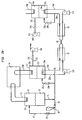
- Figure 2A is an elaboration of Figure 1 .
- Figure 2A shows in more detail apparatus providing a multi-segmented, subcooled liquid loop for an HTS cable.
- Figure 2A depicts only two segments shown only schematically and indicated by the reference numerals 21 and 22, this is for simplicity.
- this invention is applicable to a system comprising any number of segments each of which is provided with its own cooling system.
- the segments are shown to be approximately equal in length, the segments may also vary in length or, for that matter, in any other manner, e.g., pipe size, configuration, etc.
- the various segments can include different types of devices, e.g., cables and other HTS devices.
- backup refrigeration vessel 10 comprises a backup recondensing coil 11 located in headspace 12 and holds a volume of liquid nitrogen 13.
- Pressure regulator 18 operates in a standard manner to allow liquid nitrogen to flow through lines 15 and 16, into vaporizing coil 20, to cycle pressuring nitrogen gas into headspace 12 to assist in maintaining the upper pressure desired in vessel 10.
- Recondensing coil 11 is in a cooling relationship with backup mechanical refrigeration unit 14, i.e., mechanical refrigeration unit 14 cools recondensing coil 11 sufficiently so that recondensing coil 11 condenses nitrogen vapour that has evaporated from the liquid nitrogen and returns it to the volume of liquid nitrogen 13.
- cable segments 21 and 22 are essentially mirror images of one another. (The HTS cable itself is not shown.) Cable segments 21 and 22 have subcooling assemblies that comprise, respectively, heat exchangers, or more specifically here, recondensing thermosiphons, 23 and 24. Each thermosiphon comprises a headspace 23a and 24a into which recondensing coils 23b and 24b extend, respectively, in a cooling relationship similar to that described between the backup recondensing coil 11, and the backup refrigeration unit 14. In the embodiment shown in Figure 2A , recondensing coil 23b extends into the refrigeration unit 14. In this preferred configuration, one refrigeration unit operates on two recondensing coils and thus saves capital and operation costs.
- recondensing coils 11 and 23b are each serviced by separate refrigeration units.
- a single refrigeration unit can operate on three or more recondensing coils.
- two or more mechanical refrigeration units can operate on one thermosiphon.
- the refrigeration unit for servicing recondensing coil 24b is not shown. Volumes of liquid nitrogen 23c and 24c are held in vessels 23 and 24, respectively.
- condensing coils 11, 23b and 24b can be located external to, but in fluid communication with, their respective pressure vessels 10, 23 and 24.
- the coils 11, 23b and 24b may be cooled by circulating refrigeration fluid used in the mechanical refrigeration units (e.g., helium), or may simply be cold surfaces ("cold heads") that are maintained at a reduced temperature through the action of the mechanical refrigeration units.
- circulating refrigeration fluid used in the mechanical refrigeration units e.g., helium
- cold heads cold surfaces
- Both of the cable segments 21 and 22 are cooled by means of circulating liquid nitrogen, as will be described below.
- the circuit for cooling cable segment 21 comprises pipe 23d, pump 23f, pipe 23e and coil 23m.
- the circulating liquid nitrogen absorbs heat from the segment 21 and releases it to the volume of liquid nitrogen 23c.
- the segment 22 has an analogous liquid nitrogen circuit comprising pipe 24d, pump 24f, pipe 24f and coil 24m.
- Pipes 23e is connected to pipe 24e by interconnecting pipe 25.
- Pipes 16 and 23e form an open junction 26 through which backup vessel 10 is in fluid communication with the cooling circuit (loop) for cable segment 21.
- Junction 26 is the location where backup vessel 10 maintains the pressure in the circulation loops, and also serves as the point where natural liquid expansion and contraction is accommodated through the use of vessel 10 as an expansion tank.
- subcooled liquid nitrogen is circulated in the cooling loops for the cable segments 21 and 22.
- the subcooled liquid nitrogen is circulated through pipes 23d-e and 24d-e by the pumps 23f and 24f, respectively.
- the temperature of the liquid nitrogen is lowest as it leaves the respective thermosiphons 23 or 24 and highest as it returns to the respective thermosiphons 23 or 24.
- the warmed liquid is cooled by heat exchange with the lower temperature volumes liquid 23c and 24c, respectively, which in turn will cause some liquid in the volumes 23c and 24c to boil.
- evaporating coils 23m and 24m liquid nitrogen is constantly evaporating into the head space of the respective thermosiphons 23 and 24. This evaporation would cause the pressure to raise inside the thermosiphons, which is prevented through the action of recondensing coils 23b and 24b, respectively.
- Recondensing coils 23b and 24b are supplied with refrigeration from the mechanical refrigeration units (e.g., mechanical refrigeration unit 14 for recondensing coil 23b) at a rate just sufficient to condense the evaporating liquid and maintain the desired thermosiphon temperature and pressure.
- thermosiphon pressure or alternative the cooling loop temperature.
- PID proportional-integral-differential
- the vessel 23 has associated therewith valves 23h and 23j.
- the vessel 24 has a similar pair of valves 24h and 24j associated therewith. These valves are normally closed. Downstream of valves 23j and 24j are positioned vacuum pumps 23k and 24k respectively.
- the pair of valves 23h/j or 24h/j associated therewith are activated and open. For purposes of illustration, if the failure is of the refrigeration unit responsible for maintaining the liquid nitrogen in thermosiphon 24, then the closed bath of liquid nitrogen in thermosiphon 24, which normally is maintained at a constant pressure through a balance between boiling and recondensation, will tend to rise in pressure.
- valve 24j With failure of the refrigeration unit associated with thermosiphon 24, the rising pressure causes valve 24j to open and a vacuum pump 24k to begin operation.
- the opening of valve 24j and operation of pump 24k are controlled at a rate and amount to return the rising pressure to the desired value.
- This control action is through well known on/off or PID type control logic.
- the use of vacuum pump 24k is based on a need to maintain thermosiphon 24 at a pressure below atmospheric. If the pressure to be maintained at or above normal atmospheric pressure, then vacuum pump 24k may be eliminated. (If the failure is of the refrigeration unit 14 associated with the thermosiphon vessel 23, the valve 23j and vacuum pump 23 to operate analogously to the valve 24, and vacuum pump 24k.)
- the vacuum pumps 23k and 24k are typically required to operate under cold conditions.
- vent stream passing through pipe 23i or 24i may be warmed to prevent the pump 23k or 24k being subjected to low temperatures.
- valve 24j and vacuum pump 24k maintains the bath pressure, the liquid level drops. Ultimately the ability to cool the subcooled liquid loop for cable segment 22 would be lost were it not for the means to be described below.
- thermosiphon vessel 24 The level of liquid nitrogen 24c is maintained in thermosiphon vessel 24 by opening valve 24h, which admits the higher pressure liquid nitrogen from loop 24e, 24f, 24d, 24m into the bath.
- the opening of valve 24h is controlled at a rate and amount to return the lowering level of the volume of liquid nitrogen 24c to the desired level.
- This control action is through well known on/off or PID type control logic.
- the thermodynamics and flow rates of the process ensure that the mass flow of makeup liquid, i.e., liquid nitrogen, will be much less than the flow rate of the circulated subcooled liquid nitrogen. Conservation of mass causes an equal amount of liquid to be withdrawn from the subcooling loop of cable segment 22, which in turn is replenished from the subcooling loop for cable segment 21 by way of connecting pipe 25.
- This liquid nitrogen is withdrawn from backup refrigeration vessel 10 through pipes 15, 16 and junction 26.
- the entire process occurs with no requirement for additional control logic, and it has little or no effect on the cable cooling characteristics of the subcooled liquid loops.
- the level of liquid nitrogen in the vessel 23 is analogously maintained in the event of the vacuum pump 23k being called on to operate.
- the amount of liquid being circulated through the cooling circuits may be adjusted by pumps 23f and 24f during back-up operation to compensate for the small change in flow caused by this process.
- the only significant impact is a loss of liquid backup which will cause normal pressure building coil 20 to operate to a greater extent.
- the vessel 10 is provided with a liquid inlet (not shown) for this purpose.
- thermosiphon vessel 23 has recondensing coils 23b and 23b' extending into its headspace 23a from mechanical refrigeration units 14a and 14b.
- the failure or required maintenance of one refrigeration unit will generally only require the backup refrigeration system to replace the refrigeration capacity of the mechanical refrigeration unit that is inactive.
- both the backup refrigeration unit and the remaining active mechanical refrigeration unit will operate together.
- both the mechanical refrigeration unit or units servicing a cooling loop can be operated in conjunction with the backup refrigeration system to provide increased overall refrigeration capacity as the need arises, e.g., in a peak-shaving situation.
- thermosiphons The subcooled liquid nitrogen loop described above is cooled by hybrid heat exchangers, i.e., the thermosiphons.
- Alternative heat exchangers can also be used in the practice of this invention. While these do not offer the dual cooling mode flexibility of a thermosiphon, they are equally viable heat exchange options for each mode of cooling. Since each is focused on its own particular source of cooling, they are illustrative of the dual modes of operation of the proposed thermosiphon.
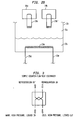
- FIG 3 is a schematic of a simple and traditional counter flow heat exchanger for a mechanical refrigeration source.
- the coolant e.g., helium gas
- the coolant After performing its cooling duty in the heat exchanger, the coolant leaves the exchanger at a warmer temperature than it enters the heat exchanger, the exact exit temperature dependent upon such variables as the nature of the coolant, flow rate and cooling duty (typically measured in watts).
- Other types of heat exchangers can be used in the practice of this invention depending upon the nature of the mechanical refrigeration unit. For example, in the event the mechanical refrigeration source uses a "cold head", then the heat exchanger can be as simple as a coil of tubing around the cold head.
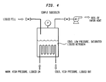
- Figure 4 illustrates the simplest heat exchanger in which the source of refrigeration is bulk liquid nitrogen.
- This form of traditional subcooler is well known in the art.
- the bath is operated at an unusually low pressure (subatmospheric for bath temperatures below 77K).
- the liquid supply (which may be at any arbitrary supply pressure greater than the bath pressure) simply operates to maintain a prescribed bath level.
- the bath will generally operate in a saturation state, i.e., the liquid will be at its boiling point that uniquely depends on the bath pressure.
- the bath In the simplest possible subcooler, the bath is exposed to ambient conditions and any vent or vapor simply exits through an opening to the outside. In this case, the pressure is atmospheric and the boiling point is about 77K. To operate at a reduced pressure (which implies a lower bath temperature), a vacuum pump/blower is throttled to maintain a prescribed bath pressure. As opposed to the simple heat exchanger of Figure 3 , the thermodynamic process is more complex. Because the bath is at its boiling point, which is generally colder than the incoming liquid to be cooled, there is a boil-off occurring that is proportional to the amount of cooling required. Modest complexity is present in that the vent flow rate through the pump/blower is the sum of two flows.
- the first is from the boil-off occurring in the bath from the heat exchanger coils, and the second comes from the liquid nitrogen supplied to keep the bath full.
- the liquid nitrogen will "flash" as it depressurizes into the lower pressure environment of the bath. Thermodynamically, this is termed an isenthalpic (constant enthalpy) expansion.
- Some "flash" gas may also be formed upstream in the liquid nitrogen piping. The subsequent liquid plus vapor that enters the bath from the fill line is saturated and at a temperature equal to the bath temperature.
Landscapes
- Engineering & Computer Science (AREA)
- Physics & Mathematics (AREA)
- Mechanical Engineering (AREA)
- Thermal Sciences (AREA)
- General Engineering & Computer Science (AREA)
- Superconductors And Manufacturing Methods Therefor (AREA)
- Separation By Low-Temperature Treatments (AREA)
Applications Claiming Priority (1)
| Application Number | Priority Date | Filing Date | Title |
|---|---|---|---|
| US10/953,030 US7263845B2 (en) | 2004-09-29 | 2004-09-29 | Backup cryogenic refrigeration system |
Publications (3)
| Publication Number | Publication Date |
|---|---|
| EP1643197A2 EP1643197A2 (en) | 2006-04-05 |
| EP1643197A3 EP1643197A3 (en) | 2007-04-18 |
| EP1643197B1 true EP1643197B1 (en) | 2010-11-24 |
Family
ID=35539575
Family Applications (1)
| Application Number | Title | Priority Date | Filing Date |
|---|---|---|---|
| EP05256014A Not-in-force EP1643197B1 (en) | 2004-09-29 | 2005-09-27 | Backup cryogenic refrigeration system |
Country Status (11)
| Country | Link |
|---|---|
| US (1) | US7263845B2 (enExample) |
| EP (1) | EP1643197B1 (enExample) |
| JP (1) | JP2006100275A (enExample) |
| KR (1) | KR20060051770A (enExample) |
| CN (1) | CN1773632B (enExample) |
| AT (1) | ATE489592T1 (enExample) |
| AU (1) | AU2005205819B2 (enExample) |
| CA (1) | CA2517532A1 (enExample) |
| DE (1) | DE602005024908D1 (enExample) |
| MX (1) | MXPA05010328A (enExample) |
| TW (1) | TW200626853A (enExample) |
Cited By (3)
| Publication number | Priority date | Publication date | Assignee | Title |
|---|---|---|---|---|
| US11908593B2 (en) | 2020-11-18 | 2024-02-20 | VEIR, Inc. | Conductor systems for suspended or underground transmission lines |
| US12020831B2 (en) * | 2020-11-18 | 2024-06-25 | VEIR, Inc. | Suspended superconducting transmission lines |
| US12232298B2 (en) | 2020-11-18 | 2025-02-18 | VEIR, Inc. | Systems and methods for cooling of superconducting power transmission lines |
Families Citing this family (41)
| Publication number | Priority date | Publication date | Assignee | Title |
|---|---|---|---|---|
| US20060150639A1 (en) * | 2005-01-13 | 2006-07-13 | Zia Jalal H | Cable cooling system |
| US7228686B2 (en) * | 2005-07-26 | 2007-06-12 | Praxair Technology, Inc. | Cryogenic refrigeration system for superconducting devices |
| US7484372B2 (en) * | 2006-03-06 | 2009-02-03 | Linde, Inc. | Multi-bath apparatus and method for cooling superconductors |
| US7752895B2 (en) * | 2006-11-30 | 2010-07-13 | Chevron Oronite S.A. | Method for using an alternate pressure viscometer |
| DE102007011530A1 (de) * | 2007-03-09 | 2008-09-11 | Bayerische Motoren Werke Aktiengesellschaft | Verfahren zum Befüllen eines für ein kryogenes Speichermedium, insbesondere Wasserstoff, vorgesehenen Druckspeichers |
| US7621148B1 (en) | 2007-08-07 | 2009-11-24 | Dain John F | Ultra-low temperature bio-sample storage system |
| US7823394B2 (en) * | 2007-11-02 | 2010-11-02 | Reflect Scientific, Inc. | Thermal insulation technique for ultra low temperature cryogenic processor |
| KR100893047B1 (ko) * | 2008-01-25 | 2009-04-15 | 엘에스전선 주식회사 | 초전도 케이블 |
| US8343524B2 (en) | 2008-07-31 | 2013-01-01 | Clarke Mosquito Control Products, Inc. | Extended release tablet and method for making and using same |
| US20100058806A1 (en) * | 2008-09-09 | 2010-03-11 | General Electric Company | Backup power system for cryo-cooled elements in wind turbines |
| US20110179667A1 (en) * | 2009-09-17 | 2011-07-28 | Lee Ron C | Freeze drying system |
| ES2380433T3 (es) * | 2009-11-26 | 2012-05-11 | Nexans | Procedimiento para el funcionamiento de una disposición con al menos un cable superconductor |
| US8534079B2 (en) * | 2010-03-18 | 2013-09-17 | Chart Inc. | Freezer with liquid cryogen refrigerant and method |
| US9011420B2 (en) * | 2010-10-27 | 2015-04-21 | Medtronic Cryocath Lp | Compatible cryogenic cooling system |
| CN103842746B (zh) * | 2011-09-28 | 2016-02-17 | 皇家飞利浦有限公司 | 用于无致冷剂mri磁体的高效热交换器 |
| EP2608223B1 (de) * | 2011-12-19 | 2014-04-23 | Nexans | Verfahren zum Kühlen einer Anlage für supraleitfähige Kabel |
| EP2631567A1 (en) | 2012-02-24 | 2013-08-28 | Airbus Operations GmbH | Cooling system with a plurality of super-coolers |
| EP2631564B1 (en) * | 2012-02-24 | 2016-09-28 | Airbus Operations GmbH | Reliable cooling system for operation with a two-phase refrigerant |
| DE102012206296A1 (de) * | 2012-04-17 | 2013-10-17 | Siemens Aktiengesellschaft | Anlage zur Speicherung und Abgabe thermischer Energie und Verfahren zu deren Betrieb |
| CN102637482B (zh) * | 2012-04-19 | 2014-08-20 | 北京云电英纳超导电缆有限公司 | 一种高温超导电缆分流制冷方法及实现该方法的制冷分流箱 |
| JP6066803B2 (ja) * | 2013-03-29 | 2017-01-25 | 株式会社前川製作所 | 超電導ケーブル用冷却システム |
| DE102013011212B4 (de) * | 2013-07-04 | 2015-07-30 | Messer Group Gmbh | Vorrichtung zum Kühlen eines Verbrauchers mit einer unterkühlten Flüssigkeit in einem Kühlkreislauf |
| JP6374305B2 (ja) * | 2014-11-21 | 2018-08-15 | 住友電気工業株式会社 | 超電導ケーブルシステム |
| JP6374306B2 (ja) * | 2014-11-21 | 2018-08-15 | 住友電気工業株式会社 | 超電導ケーブルシステム |
| JP6527353B2 (ja) * | 2015-03-12 | 2019-06-05 | 株式会社前川製作所 | 超電導体の冷却装置 |
| WO2017177317A1 (en) | 2016-04-11 | 2017-10-19 | Geoff Rowe | A system and method for liquefying production gas from a gas source |
| WO2017214723A1 (en) | 2016-06-13 | 2017-12-21 | Geoff Rowe | System, method and apparatus for the regeneration of nitrogen energy within a closed loop cryogenic system |
| EP3361187A1 (de) * | 2017-02-08 | 2018-08-15 | Linde Aktiengesellschaft | Verfahren und vorrichtung zum kühlen eines verbrauchers sowie system mit entsprechender vorrichtung und verbraucher |
| USD847962S1 (en) | 2017-03-10 | 2019-05-07 | Samsung Electronics Co., Ltd. | Air conditioner grille |
| USD847317S1 (en) | 2017-03-10 | 2019-04-30 | Samsung Electronics Co., Ltd. | Air conditioner |
| DE102017002475A1 (de) * | 2017-03-14 | 2018-09-20 | Linde Aktiengesellschaft | Verfahren und Vorrichtung zum Kühlen einer Anordnung mit einer Stromführung sowie System mit entsprechender Vorrichtung |
| JP6975019B2 (ja) * | 2017-10-27 | 2021-12-01 | 住友重機械工業株式会社 | 極低温システム |
| CN107728673B (zh) * | 2017-11-23 | 2023-05-02 | 深圳市共享能源技术有限公司 | 温控调节系统 |
| EP3511649B1 (de) * | 2018-01-12 | 2022-01-26 | Linde GmbH | Verfahren und vorrichtung zum kühlen eines verbrauchers sowie system mit entsprechender vorrichtung und verbraucher |
| EP3511650B1 (de) * | 2018-01-12 | 2022-01-26 | Linde GmbH | Verfahren und vorrichtung zum kühlen eines verbrauchers sowie system mit entsprechender vorrichtung und verbraucher |
| CN108562612B (zh) * | 2018-06-13 | 2024-01-19 | 中国科学院理化技术研究所 | 用于低温辐射性能测试的样品杆装置及测试设备 |
| US11465656B2 (en) * | 2019-07-12 | 2022-10-11 | Trinity Rail Group, Llc | Railcar backup cooling system |
| KR20230069044A (ko) * | 2020-05-20 | 2023-05-18 | 레르 리키드 쏘시에떼 아노님 뿌르 레뜌드 에렉스뿔라따시옹 데 프로세데 조르즈 클로드 | 시스템을 120k 내지 200k 범위에서 냉각시키기 위한 방법 |
| CN111934059B (zh) * | 2020-05-26 | 2022-03-18 | 南方电网调峰调频发电有限公司 | 一种向集群电化学储能装置供冷的方法 |
| CN112485557B (zh) * | 2020-11-03 | 2024-05-31 | 国网辽宁省电力有限公司电力科学研究院 | 三相同轴高温超导电缆系统载流量和温度监测装置及方法 |
| EP4623238A1 (en) * | 2022-11-23 | 2025-10-01 | Verne Inc. | System and method for cryo-compressed hydrogen production and utilization |
Family Cites Families (21)
| Publication number | Priority date | Publication date | Assignee | Title |
|---|---|---|---|---|
| GB1482967A (en) | 1973-10-24 | 1977-08-17 | Siemens Ag | Superconductive electric cable and cooling apparatus therefor |
| US3950606A (en) | 1973-10-24 | 1976-04-13 | Siemens Aktiengesellschaft | Apparatus and method for cooling a superconducting cable |
| SU714511A1 (ru) | 1976-01-08 | 1980-02-05 | Государственный Научно-Исследовательский Энергетический Институт Им. Г.М. Кржижановского | Гибкий многофазный кабель переменного тока |
| US4020274A (en) | 1976-01-27 | 1977-04-26 | The United States Of America As Represented By The United States Energy Research And Development Administration | Superconducting cable cooling system by helium gas and a mixture of gas and liquid helium |
| US4020275A (en) | 1976-01-27 | 1977-04-26 | The United States Of America As Represented By The United States Energy Research And Development Administration | Superconducting cable cooling system by helium gas at two pressures |
| US4541248A (en) * | 1983-12-15 | 1985-09-17 | Chicago Bridge & Iron Company | Constant temperature refrigeration system for a freeze heat exchanger |
| US5042262A (en) * | 1990-05-08 | 1991-08-27 | Liquid Carbonic Corporation | Food freezer |
| DE4332156A1 (de) * | 1993-09-22 | 1995-03-30 | Inst Luft Kaeltetech Gem Gmbh | Einrichtung zur autarken Kühlung hochtemperatursupraleitender Bauteile, vorzugsweise Sensoren |
| US5698210A (en) | 1995-03-17 | 1997-12-16 | Lee County Mosquito Control District | Controlled delivery compositions and processes for treating organisms in a column of water or on land |
| IT1277740B1 (it) | 1995-12-28 | 1997-11-12 | Pirelli Cavi S P A Ora Pirelli | Cavo superconduttore per alta potenza |
| JPH1073333A (ja) * | 1996-08-29 | 1998-03-17 | Sumitomo Heavy Ind Ltd | 極低温冷却装置 |
| FR2775846B1 (fr) | 1998-03-05 | 2000-06-23 | Alsthom Cge Alcatel | Procede pour le maintien a basse temperature d'une cryoliaison supraconductrice |
| US6354087B1 (en) * | 1998-05-22 | 2002-03-12 | Sumitomo Electric Industries, Ltd | Method and apparatus for cooling superconductor |
| EP1115997A2 (en) * | 1998-09-14 | 2001-07-18 | Massachusetts Institute Of Technology | Superconducting apparatuses and cooling methods |
| US7009104B2 (en) * | 2000-12-27 | 2006-03-07 | Pirelli Cavi E Sistemi S.P.A. | Superconducting cable |
| US6442949B1 (en) * | 2001-07-12 | 2002-09-03 | General Electric Company | Cryongenic cooling refrigeration system and method having open-loop short term cooling for a superconducting machine |
| DE10217092A1 (de) | 2002-04-17 | 2003-11-06 | Linde Ag | Kühlung von Hochtemperatursupraleitern |
| JP2003336923A (ja) * | 2002-05-20 | 2003-11-28 | Central Japan Railway Co | 極低温冷凍装置 |
| US6640557B1 (en) * | 2002-10-23 | 2003-11-04 | Praxair Technology, Inc. | Multilevel refrigeration for high temperature superconductivity |
| CN2619187Y (zh) * | 2003-03-25 | 2004-06-02 | 范朝阳 | 蓄冷、蓄热无机热、冷传导中央空调机 |
| US6854276B1 (en) | 2003-06-19 | 2005-02-15 | Superpower, Inc | Method and apparatus of cryogenic cooling for high temperature superconductor devices |
-
2004
- 2004-09-29 US US10/953,030 patent/US7263845B2/en not_active Expired - Fee Related
-
2005
- 2005-08-30 CA CA002517532A patent/CA2517532A1/en not_active Abandoned
- 2005-09-05 AU AU2005205819A patent/AU2005205819B2/en not_active Ceased
- 2005-09-06 TW TW094130458A patent/TW200626853A/zh unknown
- 2005-09-27 AT AT05256014T patent/ATE489592T1/de not_active IP Right Cessation
- 2005-09-27 EP EP05256014A patent/EP1643197B1/en not_active Not-in-force
- 2005-09-27 DE DE602005024908T patent/DE602005024908D1/de active Active
- 2005-09-27 MX MXPA05010328A patent/MXPA05010328A/es not_active Application Discontinuation
- 2005-09-28 JP JP2005281836A patent/JP2006100275A/ja active Pending
- 2005-09-28 KR KR1020050090656A patent/KR20060051770A/ko not_active Withdrawn
- 2005-09-29 CN CN2005101089808A patent/CN1773632B/zh not_active Expired - Fee Related
Cited By (3)
| Publication number | Priority date | Publication date | Assignee | Title |
|---|---|---|---|---|
| US11908593B2 (en) | 2020-11-18 | 2024-02-20 | VEIR, Inc. | Conductor systems for suspended or underground transmission lines |
| US12020831B2 (en) * | 2020-11-18 | 2024-06-25 | VEIR, Inc. | Suspended superconducting transmission lines |
| US12232298B2 (en) | 2020-11-18 | 2025-02-18 | VEIR, Inc. | Systems and methods for cooling of superconducting power transmission lines |
Also Published As
| Publication number | Publication date |
|---|---|
| US7263845B2 (en) | 2007-09-04 |
| ATE489592T1 (de) | 2010-12-15 |
| EP1643197A3 (en) | 2007-04-18 |
| CN1773632A (zh) | 2006-05-17 |
| DE602005024908D1 (de) | 2011-01-05 |
| KR20060051770A (ko) | 2006-05-19 |
| AU2005205819B2 (en) | 2010-10-07 |
| CN1773632B (zh) | 2010-05-12 |
| TW200626853A (en) | 2006-08-01 |
| EP1643197A2 (en) | 2006-04-05 |
| AU2005205819A1 (en) | 2006-04-13 |
| MXPA05010328A (es) | 2006-04-03 |
| CA2517532A1 (en) | 2006-03-29 |
| US20060065004A1 (en) | 2006-03-30 |
| JP2006100275A (ja) | 2006-04-13 |
Similar Documents
| Publication | Publication Date | Title |
|---|---|---|
| EP1643197B1 (en) | Backup cryogenic refrigeration system | |
| EP2196722B1 (en) | Device for re-liquefaction of liquefied gas, liquefied gas storage facility and liquefied gas carrying vessel equipped with the device, and method of re-liquefaction of liquefied gas | |
| EP1498670B1 (en) | Cryogenic cooling system and method with cold storage device | |
| KR102053387B1 (ko) | 냉각 회로 내의 과냉 액체를 이용한 소비자 냉각 장치 | |
| US7185501B2 (en) | Cryogenic cooling system and method with backup cold storage device | |
| JP2005351613A (ja) | 冷却装置 | |
| JP7346453B2 (ja) | 液化水素を貯蔵し、分配する方法及び設備 | |
| KR102124677B1 (ko) | 냉동 및/또는 액화 장치 및 대응 방법 | |
| JPH07218033A (ja) | Lngタンクの冷却装置 | |
| JP2016169880A (ja) | 超電導ケーブル冷却装置、及び超電導ケーブルの冷却方法 | |
| EP1825485A1 (en) | Magnetic apparatus and method | |
| JP2602982B2 (ja) | 冷却装置 | |
| US11153991B2 (en) | Method and apparatus for cooling a load and system comprising corresponding apparatus and load | |
| US11913714B2 (en) | Dilution refrigerator with continuous flow helium liquefier | |
| JPH08159584A (ja) | ヘリウム液化冷凍装置及びその運転方法 | |
| JPH0774019A (ja) | 極低温冷却システム | |
| CN120176397A (zh) | 用于将液氦转移到应用低温恒温器中的设备和方法 | |
| KR20230010220A (ko) | 재액화 시스템 운용 방법 | |
| Ligi et al. | DAΦNE Cryogenic Cooling System: Status and Perspectives |
Legal Events
| Date | Code | Title | Description |
|---|---|---|---|
| PUAI | Public reference made under article 153(3) epc to a published international application that has entered the european phase |
Free format text: ORIGINAL CODE: 0009012 |
|
| AK | Designated contracting states |
Kind code of ref document: A2 Designated state(s): AT BE BG CH CY CZ DE DK EE ES FI FR GB GR HU IE IS IT LI LT LU LV MC NL PL PT RO SE SI SK TR |
|
| AX | Request for extension of the european patent |
Extension state: AL BA HR MK YU |
|
| PUAL | Search report despatched |
Free format text: ORIGINAL CODE: 0009013 |
|
| AK | Designated contracting states |
Kind code of ref document: A3 Designated state(s): AT BE BG CH CY CZ DE DK EE ES FI FR GB GR HU IE IS IT LI LT LU LV MC NL PL PT RO SE SI SK TR |
|
| AX | Request for extension of the european patent |
Extension state: AL BA HR MK YU |
|
| 17P | Request for examination filed |
Effective date: 20070919 |
|
| 17Q | First examination report despatched |
Effective date: 20071018 |
|
| AKX | Designation fees paid |
Designated state(s): AT BE BG CH CY CZ DE DK EE ES FI FR GB GR HU IE IS IT LI LT LU LV MC NL PL PT RO SE SI SK TR |
|
| RAP1 | Party data changed (applicant data changed or rights of an application transferred) |
Owner name: LINDE LLC |
|
| GRAP | Despatch of communication of intention to grant a patent |
Free format text: ORIGINAL CODE: EPIDOSNIGR1 |
|
| GRAS | Grant fee paid |
Free format text: ORIGINAL CODE: EPIDOSNIGR3 |
|
| GRAA | (expected) grant |
Free format text: ORIGINAL CODE: 0009210 |
|
| AK | Designated contracting states |
Kind code of ref document: B1 Designated state(s): AT BE BG CH CY CZ DE DK EE ES FI FR GB GR HU IE IS IT LI LT LU LV MC NL PL PT RO SE SI SK TR |
|
| REG | Reference to a national code |
Ref country code: GB Ref legal event code: FG4D |
|
| REG | Reference to a national code |
Ref country code: CH Ref legal event code: EP |
|
| REG | Reference to a national code |
Ref country code: IE Ref legal event code: FG4D |
|
| REF | Corresponds to: |
Ref document number: 602005024908 Country of ref document: DE Date of ref document: 20110105 Kind code of ref document: P |
|
| REG | Reference to a national code |
Ref country code: NL Ref legal event code: T3 |
|
| LTIE | Lt: invalidation of european patent or patent extension |
Effective date: 20101124 |
|
| PG25 | Lapsed in a contracting state [announced via postgrant information from national office to epo] |
Ref country code: LT Free format text: LAPSE BECAUSE OF FAILURE TO SUBMIT A TRANSLATION OF THE DESCRIPTION OR TO PAY THE FEE WITHIN THE PRESCRIBED TIME-LIMIT Effective date: 20101124 |
|
| PG25 | Lapsed in a contracting state [announced via postgrant information from national office to epo] |
Ref country code: FI Free format text: LAPSE BECAUSE OF FAILURE TO SUBMIT A TRANSLATION OF THE DESCRIPTION OR TO PAY THE FEE WITHIN THE PRESCRIBED TIME-LIMIT Effective date: 20101124 Ref country code: LV Free format text: LAPSE BECAUSE OF FAILURE TO SUBMIT A TRANSLATION OF THE DESCRIPTION OR TO PAY THE FEE WITHIN THE PRESCRIBED TIME-LIMIT Effective date: 20101124 Ref country code: PT Free format text: LAPSE BECAUSE OF FAILURE TO SUBMIT A TRANSLATION OF THE DESCRIPTION OR TO PAY THE FEE WITHIN THE PRESCRIBED TIME-LIMIT Effective date: 20110324 Ref country code: CY Free format text: LAPSE BECAUSE OF FAILURE TO SUBMIT A TRANSLATION OF THE DESCRIPTION OR TO PAY THE FEE WITHIN THE PRESCRIBED TIME-LIMIT Effective date: 20101124 Ref country code: AT Free format text: LAPSE BECAUSE OF FAILURE TO SUBMIT A TRANSLATION OF THE DESCRIPTION OR TO PAY THE FEE WITHIN THE PRESCRIBED TIME-LIMIT Effective date: 20101124 Ref country code: IS Free format text: LAPSE BECAUSE OF FAILURE TO SUBMIT A TRANSLATION OF THE DESCRIPTION OR TO PAY THE FEE WITHIN THE PRESCRIBED TIME-LIMIT Effective date: 20110324 Ref country code: SI Free format text: LAPSE BECAUSE OF FAILURE TO SUBMIT A TRANSLATION OF THE DESCRIPTION OR TO PAY THE FEE WITHIN THE PRESCRIBED TIME-LIMIT Effective date: 20101124 Ref country code: BG Free format text: LAPSE BECAUSE OF FAILURE TO SUBMIT A TRANSLATION OF THE DESCRIPTION OR TO PAY THE FEE WITHIN THE PRESCRIBED TIME-LIMIT Effective date: 20110224 Ref country code: SE Free format text: LAPSE BECAUSE OF FAILURE TO SUBMIT A TRANSLATION OF THE DESCRIPTION OR TO PAY THE FEE WITHIN THE PRESCRIBED TIME-LIMIT Effective date: 20101124 |
|
| PG25 | Lapsed in a contracting state [announced via postgrant information from national office to epo] |
Ref country code: GR Free format text: LAPSE BECAUSE OF FAILURE TO SUBMIT A TRANSLATION OF THE DESCRIPTION OR TO PAY THE FEE WITHIN THE PRESCRIBED TIME-LIMIT Effective date: 20110225 |
|
| PG25 | Lapsed in a contracting state [announced via postgrant information from national office to epo] |
Ref country code: ES Free format text: LAPSE BECAUSE OF FAILURE TO SUBMIT A TRANSLATION OF THE DESCRIPTION OR TO PAY THE FEE WITHIN THE PRESCRIBED TIME-LIMIT Effective date: 20110307 Ref country code: EE Free format text: LAPSE BECAUSE OF FAILURE TO SUBMIT A TRANSLATION OF THE DESCRIPTION OR TO PAY THE FEE WITHIN THE PRESCRIBED TIME-LIMIT Effective date: 20101124 Ref country code: BE Free format text: LAPSE BECAUSE OF FAILURE TO SUBMIT A TRANSLATION OF THE DESCRIPTION OR TO PAY THE FEE WITHIN THE PRESCRIBED TIME-LIMIT Effective date: 20101124 Ref country code: CZ Free format text: LAPSE BECAUSE OF FAILURE TO SUBMIT A TRANSLATION OF THE DESCRIPTION OR TO PAY THE FEE WITHIN THE PRESCRIBED TIME-LIMIT Effective date: 20101124 |
|
| PG25 | Lapsed in a contracting state [announced via postgrant information from national office to epo] |
Ref country code: DK Free format text: LAPSE BECAUSE OF FAILURE TO SUBMIT A TRANSLATION OF THE DESCRIPTION OR TO PAY THE FEE WITHIN THE PRESCRIBED TIME-LIMIT Effective date: 20101124 Ref country code: SK Free format text: LAPSE BECAUSE OF FAILURE TO SUBMIT A TRANSLATION OF THE DESCRIPTION OR TO PAY THE FEE WITHIN THE PRESCRIBED TIME-LIMIT Effective date: 20101124 Ref country code: RO Free format text: LAPSE BECAUSE OF FAILURE TO SUBMIT A TRANSLATION OF THE DESCRIPTION OR TO PAY THE FEE WITHIN THE PRESCRIBED TIME-LIMIT Effective date: 20101124 Ref country code: PL Free format text: LAPSE BECAUSE OF FAILURE TO SUBMIT A TRANSLATION OF THE DESCRIPTION OR TO PAY THE FEE WITHIN THE PRESCRIBED TIME-LIMIT Effective date: 20101124 |
|
| PLBE | No opposition filed within time limit |
Free format text: ORIGINAL CODE: 0009261 |
|
| STAA | Information on the status of an ep patent application or granted ep patent |
Free format text: STATUS: NO OPPOSITION FILED WITHIN TIME LIMIT |
|
| 26N | No opposition filed |
Effective date: 20110825 |
|
| REG | Reference to a national code |
Ref country code: DE Ref legal event code: R097 Ref document number: 602005024908 Country of ref document: DE Effective date: 20110825 |
|
| REG | Reference to a national code |
Ref country code: NL Ref legal event code: V1 Effective date: 20120401 |
|
| PG25 | Lapsed in a contracting state [announced via postgrant information from national office to epo] |
Ref country code: MC Free format text: LAPSE BECAUSE OF NON-PAYMENT OF DUE FEES Effective date: 20110930 |
|
| REG | Reference to a national code |
Ref country code: CH Ref legal event code: PL |
|
| GBPC | Gb: european patent ceased through non-payment of renewal fee |
Effective date: 20110927 |
|
| PG25 | Lapsed in a contracting state [announced via postgrant information from national office to epo] |
Ref country code: IT Free format text: LAPSE BECAUSE OF NON-PAYMENT OF DUE FEES Effective date: 20110927 |
|
| REG | Reference to a national code |
Ref country code: IE Ref legal event code: MM4A |
|
| REG | Reference to a national code |
Ref country code: FR Ref legal event code: ST Effective date: 20120531 |
|
| REG | Reference to a national code |
Ref country code: DE Ref legal event code: R119 Ref document number: 602005024908 Country of ref document: DE Effective date: 20120403 |
|
| PG25 | Lapsed in a contracting state [announced via postgrant information from national office to epo] |
Ref country code: DE Free format text: LAPSE BECAUSE OF NON-PAYMENT OF DUE FEES Effective date: 20120403 Ref country code: LI Free format text: LAPSE BECAUSE OF NON-PAYMENT OF DUE FEES Effective date: 20110930 Ref country code: CH Free format text: LAPSE BECAUSE OF NON-PAYMENT OF DUE FEES Effective date: 20110930 Ref country code: IE Free format text: LAPSE BECAUSE OF NON-PAYMENT OF DUE FEES Effective date: 20110927 Ref country code: NL Free format text: LAPSE BECAUSE OF NON-PAYMENT OF DUE FEES Effective date: 20120401 |
|
| PG25 | Lapsed in a contracting state [announced via postgrant information from national office to epo] |
Ref country code: FR Free format text: LAPSE BECAUSE OF NON-PAYMENT OF DUE FEES Effective date: 20110930 Ref country code: GB Free format text: LAPSE BECAUSE OF NON-PAYMENT OF DUE FEES Effective date: 20110927 |
|
| PG25 | Lapsed in a contracting state [announced via postgrant information from national office to epo] |
Ref country code: LU Free format text: LAPSE BECAUSE OF NON-PAYMENT OF DUE FEES Effective date: 20110927 |
|
| PG25 | Lapsed in a contracting state [announced via postgrant information from national office to epo] |
Ref country code: TR Free format text: LAPSE BECAUSE OF FAILURE TO SUBMIT A TRANSLATION OF THE DESCRIPTION OR TO PAY THE FEE WITHIN THE PRESCRIBED TIME-LIMIT Effective date: 20101124 |
|
| PG25 | Lapsed in a contracting state [announced via postgrant information from national office to epo] |
Ref country code: HU Free format text: LAPSE BECAUSE OF FAILURE TO SUBMIT A TRANSLATION OF THE DESCRIPTION OR TO PAY THE FEE WITHIN THE PRESCRIBED TIME-LIMIT Effective date: 20101124 |