EP1643153A2 - Structure de support de câble de frein pour un frein à tambour - Google Patents
Structure de support de câble de frein pour un frein à tambour Download PDFInfo
- Publication number
- EP1643153A2 EP1643153A2 EP05292027A EP05292027A EP1643153A2 EP 1643153 A2 EP1643153 A2 EP 1643153A2 EP 05292027 A EP05292027 A EP 05292027A EP 05292027 A EP05292027 A EP 05292027A EP 1643153 A2 EP1643153 A2 EP 1643153A2
- Authority
- EP
- European Patent Office
- Prior art keywords
- cable
- brake
- back plate
- seating
- brake lever
- Prior art date
- Legal status (The legal status is an assumption and is not a legal conclusion. Google has not performed a legal analysis and makes no representation as to the accuracy of the status listed.)
- Withdrawn
Links
Images


Classifications
-
- F—MECHANICAL ENGINEERING; LIGHTING; HEATING; WEAPONS; BLASTING
- F16—ENGINEERING ELEMENTS AND UNITS; GENERAL MEASURES FOR PRODUCING AND MAINTAINING EFFECTIVE FUNCTIONING OF MACHINES OR INSTALLATIONS; THERMAL INSULATION IN GENERAL
- F16D—COUPLINGS FOR TRANSMITTING ROTATION; CLUTCHES; BRAKES
- F16D65/00—Parts or details
- F16D65/14—Actuating mechanisms for brakes; Means for initiating operation at a predetermined position
- F16D65/16—Actuating mechanisms for brakes; Means for initiating operation at a predetermined position arranged in or on the brake
- F16D65/22—Actuating mechanisms for brakes; Means for initiating operation at a predetermined position arranged in or on the brake adapted for pressing members apart, e.g. for drum brakes
-
- F—MECHANICAL ENGINEERING; LIGHTING; HEATING; WEAPONS; BLASTING
- F16—ENGINEERING ELEMENTS AND UNITS; GENERAL MEASURES FOR PRODUCING AND MAINTAINING EFFECTIVE FUNCTIONING OF MACHINES OR INSTALLATIONS; THERMAL INSULATION IN GENERAL
- F16D—COUPLINGS FOR TRANSMITTING ROTATION; CLUTCHES; BRAKES
- F16D65/00—Parts or details
- F16D65/14—Actuating mechanisms for brakes; Means for initiating operation at a predetermined position
- F16D65/28—Actuating mechanisms for brakes; Means for initiating operation at a predetermined position arranged apart from the brake
-
- F—MECHANICAL ENGINEERING; LIGHTING; HEATING; WEAPONS; BLASTING
- F16—ENGINEERING ELEMENTS AND UNITS; GENERAL MEASURES FOR PRODUCING AND MAINTAINING EFFECTIVE FUNCTIONING OF MACHINES OR INSTALLATIONS; THERMAL INSULATION IN GENERAL
- F16D—COUPLINGS FOR TRANSMITTING ROTATION; CLUTCHES; BRAKES
- F16D2121/00—Type of actuator operation force
- F16D2121/14—Mechanical
-
- F—MECHANICAL ENGINEERING; LIGHTING; HEATING; WEAPONS; BLASTING
- F16—ENGINEERING ELEMENTS AND UNITS; GENERAL MEASURES FOR PRODUCING AND MAINTAINING EFFECTIVE FUNCTIONING OF MACHINES OR INSTALLATIONS; THERMAL INSULATION IN GENERAL
- F16D—COUPLINGS FOR TRANSMITTING ROTATION; CLUTCHES; BRAKES
- F16D2125/00—Components of actuators
- F16D2125/18—Mechanical mechanisms
- F16D2125/58—Mechanical mechanisms transmitting linear movement
- F16D2125/60—Cables or chains, e.g. Bowden cables
- F16D2125/62—Fixing arrangements therefor, e.g. cable end attachments
-
- Y—GENERAL TAGGING OF NEW TECHNOLOGICAL DEVELOPMENTS; GENERAL TAGGING OF CROSS-SECTIONAL TECHNOLOGIES SPANNING OVER SEVERAL SECTIONS OF THE IPC; TECHNICAL SUBJECTS COVERED BY FORMER USPC CROSS-REFERENCE ART COLLECTIONS [XRACs] AND DIGESTS
- Y10—TECHNICAL SUBJECTS COVERED BY FORMER USPC
- Y10T—TECHNICAL SUBJECTS COVERED BY FORMER US CLASSIFICATION
- Y10T74/00—Machine element or mechanism
- Y10T74/20—Control lever and linkage systems
- Y10T74/20396—Hand operated
- Y10T74/20402—Flexible transmitter [e.g., Bowden cable]
- Y10T74/20462—Specific cable connector or guide
Definitions
- the invention relates to a drum brake device and more particularly to a brake cable connecting apparatus for connecting a brake cable, functioning as a remote force transmitting member, to a brake lever.
- a conventional brake cable connecting apparatus for a drum brake is such that at a free end of a brake lever, a seating is extended and intersected with a brake cable at an axis thereof; that an inner cable of the brake cable is retained in a cable inserting groove formed in the seating in a back plate side; and that a cable end fitting of the brake cable is seated in the cable release side of the seating.
- the conventional type of the drum brake is disclosed in U.S. Patent Number 5,137,120.
- both ends of a coil spring are mounted on each of a cable plug-in section of the back plate and on the free end of the brake lever, forming a guiding member with a structure which makes the amount of deflection smaller by limiting the deflection of the inner cable in effect to the short section between the guiding member and the brake lever.
- the coil spring as the guiding member, is installed on the free end of the brake lever, thereby making the operation of installing the coil spring more complicated, which increased the time necessary for the installation.
- the complex shapes of the brake lever increase the material cost and manufacturing cost.
- the brake cable connecting apparatus for the drum brake according to the invention is structured such that a seating of the brake lever on which a cable end fitting is seated is intersected with the brake cable at the axis thereof; a cable inserting groove is formed in a back plate side of the seating; and a clearance is formed between the seating of the brake lever and the back plate so as to allow a forcibly deformed inner cable to pass therethrough when the inner cable of the brake cable is retained in the cable inserting groove.
- the brake cable connecting apparatus for the drum brake of the first invention in this application comprises, comprising: a brake lever pivotally supported on one of a pair of brake shoes moveably mounted on a back plate, the brake lever has a seating at a free end thereof, which is bent to extend toward the back plate and further has a cable inserting groove facing the back plate; and a brake cable routed through the back plate and connected to the free end of the brake lever, the brake cable has an inner cable and a cable end fitting fixed on an end of the inner cable that is seated on a seating formed at the free end of the brake lever, wherein a clearance is configured between an end of the seating of the brake lever and the back plate so as to allow the forcibly deformed inner cable to pass therethrough when the inner cable is inserted in the cable inserting groove.
- the brake cable connecting apparatus for the drum brake of the second invention in this application is based on the above-mentioned first invention, wherein the cable inserting groove of the seating of the brake lever is an L-shape groove consisting of two parts; a lead-in groove facing the back plate and a connecting groove extending from a bottom part of the lead-in groove in a direction which intersects the lead-in groove.
- the brake cable connecting apparatus for the drum brake of the third invention in this application is based on the above-mentioned first or second invention, wherein a cable end fitting supporter is integrally formed at the end of the seating of said brake lever so as to restrict a movement of the cable end fitting toward the back plate
- the brake cable connecting apparatus for the drum brake of the fourth invention in this application is based on the above-mentioned first through/or fourth invention, wherein the clearance between the end of the seating of the brake lever and the back plate is designed to allow the inner cable to pass therethrough but to prevent the cable end fitting from passing therethrough.
- the brake cable connecting apparatus for the drum brake according to the invention provides the following specific advantages.
- the brake cable connecting apparatus of the invention is able to provide a simple connection of the brake cable to the free end of the brake lever only by forcibly deforming the inner cable toward the back plate and moving the inner cable to the opening of the cable inserting groove because the configuration between the seating of the brake lever and the back plate is formed so as to allow the forcibly deformed inner cable to pass therethrough, and therefore even unskilled operators are able to easily perform the connecting operation of the brake cable to the brake lever.
- the brake cable connecting apparatus of the invention is able to ensure the disconnection prevention configuration of the brake cable after connecting the brake cable to the brake lever because once the cable end fitting is seated on the seating of the brake lever, the inner cable is not disconnected from the brake lever unless moving in parallel along the back plate after forcibly deforming the inner cable by an external force.
- the brake cable connecting apparatus of the invention is further able to enhance the rigid connection between the brake cable and the brake lever, i.e., making it more difficult to be disconnected, after making the connection therebetween by forming the overall shape of the cable inserting groove in the seating of the brake lever into an L-shape or/and by forming the cable end supporter integrally at the end of the seating of the brake lever.
- the brake cable connecting apparatus of the invention has a simple configuration to ensure the prevention of the brake cable disconnection utilizing the back plate, in which the seating of the brake lever is bent so as to extend toward the back plate, and the cable inserting groove is formed in the seating facing to the back plate, thereby enabling the easy production at a low cost with press work, mainly bending, while substantially reducing its weight, thereby requiring smaller space for its arrangement.
- FIG. 1 is a plan view of the drum brake device applying the brake cable connecting apparatus of a first embodiment of the invention
- FIG. 2 is a cross sectional view of FIG. 1 taken along the line II-II;
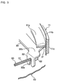
- FIG. 3 is a partly fractured perspective view of the connecting section between the free end of the brake lever and the brake cable;
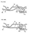
- FIG. 4 (A) is a view illustrating the connecting operation of the brake cable to the brake lever
- FIG. 4 (B) is a view illustrating the configuration to prevent disconnection of the brake cable from the brake lever
- FIG. 5 is a view illustrating the brake cable connecting apparatus of a second embodiment
- FIG. 6 is a view illustrating the brake cable connecting apparatus of a third embodiment.
- FIG. 7 is a cross sectional view of the brake cable connecting apparatus of the modification of embodiments.
- the brake cable connecting apparatus of the invention has realized the purposes of ensuring in the connecting operation of the brake cable to the brake lever both easy connecting operation and rigid connection, i.e., the condition that the brake cable cannot easily be disconnected from the brake lever after the connecting operation is completed.
- FIG. 1 shows a leading-trailing type drum brake device
- FIG. 2 is a cross sectional view of FIG. 1 taken along the line II-II;
- Brake shoes 11, 12 comprise shoe webs 11 a, 12a, shoe rims 11 b, 12b and linings 11 c, 12c, wherein the shoe webs 11 a, 12a and the shoe rims 11 b, 12b are respectively connected to form a T-shape cross-section and the linings 11 c, 12c are respectively fixed on the peripheral surfaces of the shoe rims 11 b, 12b.
- Each of the brake shoes 11, 12 is moveably mounted on a back plate 10 which is fixed to a stationary part (not shown in the figures) of a vehicle by a shoe hold mechanisms 13, 14, respectively.
- a plate-like brake lever 30 is superposed on the back plate side of the shoe web 11 a, and a proximal end 30a is pivotally supported with a pin 19 as a fulcrum at an upper side of the shoe web 11 a.
- a stopper 31 of the brake lever 30 projects toward the shoe rim and abuts against the inner circumference of the shoe rim 11 b, thereby restricting the rotation (or the counterclockwise rotation) of the brake lever 30 in the cable release direction.
- a free end 30b of the brake lever 30 has a seating 32 where a brake cable 50 (as described later) is connected.
- a shoe clearance adjustment strut 20, one of the components constituting a parking brake mechanism, is provided adjacent to the wheel cylinder 15 and is extended between the shoe web 12a of the brake shoe 12 and the brake lever 30.
- Shoe return springs 21, 22 are stretched between both brake shoes 11 and 12, which urge both brake shoes 11 and 12 toward each other and abut against the shoe clearance adjustment strut 20 and the anchor 16 to restrict the initial positions of the brake shoes 11, 12.
- the brake cable 50 is comprised of an inner cable 51, a cable end fitting 52, which is fixed on an end of the inner cable 51, and an outer casing 53, etc.
- a brake side of the inner cable 51, slidably provided in the outer casing 53, is smoothly guided in an appropriate direction by a protrusion 10a formed on the back plate 10, and the cable end fitting 52 is seated on the seating 32 of the brake lever 30.
- a casing cap 53a, fixed in the end of the outer casing 53 at a brake side, is inserted into and attached to an insertion guide 10b fixed in the back plate 10.
- the seating 32 is integrally provided in the free end 30b away from the shoe rim 11 b by bending itself at right angles toward the back plate 10 so that the cross-section forms an L-shape.
- a cable inserting groove 32a is formed in the seating 32 from the end thereof facing the back plate 10 toward the bending section to be able to seat the cable end fitting 52.
- a width of the cable inserting groove 32a is designed to allow the inner cable 51 to pass therethrough but to prevent the cable end fitting 52 from passing therethrough.
- the invention is configured such that the clearance 40 between the end of the seating 32 of the brake lever 30 and the back plate 10 is designed larger than the diameter of the inner cable 51 and smaller than the minimum outside dimension of the cable end fitting 52 in a direction perpendicular to the cable axis.
- the protrusion 10a is formed in the back plate 10 towards the bottom of the brake drum (not shown in the figures) to smoothly support the inner cable 51 in the vicinity of the cable end fitting 52.
- the functional relationship between the back plate 10 and the brake lever 30 allows the inner cable 51 to pass therethrough only on condition that the inner cable 51 is forcibly deformed but prevents the cable end fitting 52 seated in the brake lever 30 and the inner cable 51 from passing therethrough on any other conditions.
- the clearance 40 is formed such that the inner cable 51 is allowed to pass therethrough when the inner cable 51 is forcibly deformed toward the back plate 10 between the cable end fitting 52 and the protrusion 10a of the back plate 10.
- the inner cable 51 routed through the insertion guide 10b shown in FIG. 2 is smoothly guided along the protrusion 10a after being inserted within the back plate 10 as shown in FIG. 4 (A).
- the inner cable 51 is pulled enough in length so that the cable end fitting 52 goes across the seating 32, and while the cable end fitting 52 is retained in a space 41 formed by the brake lever 30, the back plate 10 and the brake shoe 11, the inner cable 51 is forcibly deformed by hand toward the back plate 10 between the protrusion 10a and the cable end fitting 52 and inserted from the side of the seating 32 to the clearance 40.
- the flexural range of the inner cable 51 is able to cover a relatively long distance from the protrusion 10a to the cable end fitting 52, which enables the inner cable 51 to be inserted, by flexing, to the clearance 40 without difficulty.
- the inner cable 51 When the inner cable 51 is released from the flexural condition at the position of the cable inserting groove 32a of the brake lever 30, the inner cable 51 moves by restoring force thereof in a restoration direction away from the back plate 10 and is retained within the cable inserting groove 32a.
- the cable end fitting 52 is seated on the seating 32 by slightly pulling the inner cable 51, thereby completing the process of connecting the brake cable 50 to the brake lever 30.
- FIG. 4 (B) shows the condition after completing the connection of the brake cable 50 to the brake lever 30.
- the inner cable 51 is retained within the cable inserting groove 32a, thereby preventing the disconnection of the brake cable 50 from the brake lever 30.
- the restoring force trying to return to a straight shape, functions as a biasing force toward the bottom of the cable inserting groove 32a, thereby preventing the cable end fitting 52 movement toward the back plate 10 unless external force is added.
- the clearance 40 is designed to be smaller than the minimum outside dimension of the cable end fitting 52, thereby preventing the disconnection of the cable end fitting 52 from the seating 32 unless the inner cable 51 is forcibly deformed.
- FIG. 4 (B) when the cable fitting 52 is seated on the seating 32, even if the inner cable 51 subsequently loosens, the prevention of the disconnection of the cable end fitting 52 from the seating 32 is able to be ensured.
- the inner cable 51 is moved backward in the cable release direction, forcibly deformed toward the same direction as the process of connecting, pushed from the cable inserting groove 32a in the above condition, and passed the clearance 40 along the back plate 10.
- FIG. 5 shows another embodiment where the cable inserting groove 132a of the seating 132 of the brake lever 30 is formed into an L-shape.
- the cable inserting groove 132a in this embodiment consists of a lead-in groove 132b formed from the end of the seating 132 toward the bending section, and a connecting groove 132c extending from a bottom inner part of the lead-in groove 132b in the direction which intersects the lead-in groove 132b.
- the inner cable 51 guided in the lead-in groove 132b via the clearance 40 between the end of the seating 132 of the brake lever 30 and the back plate 10 is guided in the connecting groove 132c and then the cable end fitting 52 is seated on the seating 132.
- a retaining groove which supports the inner cable 51 and restricts the sliding in a crosswise/lateral direction, is formed in the protrusion 10a in FIG. 1, thereby restricting the free sliding of the inner cable 51 along the connecting groove 132c.
- FIG. 6 shows another embodiment where a cable end supporter 232d is formed at the end of the seating 232 of the brake lever 30 as the disconnection prevention configuration of the brake cable 50 by bending/folding the plate material, which is able to prevent the cable end fitting 52 from running off the seating 232.
- the cable end supporter 232d is formed in one or both sides of the seating 232 of the brake lever 30 across the cable inserting groove 232a. As the displacement of the cable end fitting 52 is restricted also by the cable end supporter 232d shown in this embodiment, more effective prevention of the disconnection of the brake cable 50 from the brake lever 30 is ensured.
- FIG. 7 shows the modification of the above-mentioned embodiments.
- the brake cable 150 where a lever return spring 54 is freely carried over the inner cable 51, is applied and a cable guide section 17a is integrally formed in a retaining plate 17 (shown in FIG. 1) fixed together with the anchor 16 on the back plate 10 instead of the protrusion 10a of the back plate 10 as the supporting means of the inner cable 51 shown in the first embodiment.
- the brake type is not limited to the above-mentioned leading-trailing type, and the invention is clearly applicable to other types of brakes, such as a duo-servo type or a drum brake device without the wheel cylinder 15, specially designed for a parking brake.
Landscapes
- Engineering & Computer Science (AREA)
- General Engineering & Computer Science (AREA)
- Mechanical Engineering (AREA)
- Braking Arrangements (AREA)
Applications Claiming Priority (1)
| Application Number | Priority Date | Filing Date | Title |
|---|---|---|---|
| JP2004290253A JP2006105209A (ja) | 2004-10-01 | 2004-10-01 | ドラムブレーキのブレーキケーブル接続装置 |
Publications (2)
| Publication Number | Publication Date |
|---|---|
| EP1643153A2 true EP1643153A2 (fr) | 2006-04-05 |
| EP1643153A3 EP1643153A3 (fr) | 2006-05-17 |
Family
ID=35483383
Family Applications (1)
| Application Number | Title | Priority Date | Filing Date |
|---|---|---|---|
| EP05292027A Withdrawn EP1643153A3 (fr) | 2004-10-01 | 2005-09-29 | Structure de support de câble de frein pour un frein à tambour |
Country Status (5)
| Country | Link |
|---|---|
| US (1) | US20060075844A1 (fr) |
| EP (1) | EP1643153A3 (fr) |
| JP (1) | JP2006105209A (fr) |
| KR (1) | KR20060051237A (fr) |
| CN (1) | CN1755157A (fr) |
Families Citing this family (3)
| Publication number | Priority date | Publication date | Assignee | Title |
|---|---|---|---|---|
| KR101255368B1 (ko) * | 2006-06-19 | 2013-04-17 | 현대모비스 주식회사 | 차량용 주차 브레이크의 케이블 브라켓 유니트 |
| JP6270453B2 (ja) * | 2013-12-16 | 2018-01-31 | ダイハツ工業株式会社 | 自動車用内燃機関のアクセルケーブル保持用ブラケット |
| CN107882854A (zh) * | 2017-11-30 | 2018-04-06 | 上汽通用五菱汽车股份有限公司 | 一种汽车拉索固定卡扣 |
Citations (5)
| Publication number | Priority date | Publication date | Assignee | Title |
|---|---|---|---|---|
| US2924116A (en) * | 1955-11-14 | 1960-02-09 | Bendix Aviat Corp | Parking brake |
| US3255849A (en) * | 1964-04-20 | 1966-06-14 | Kelsey Hayes Co | Parking brake |
| US4872533A (en) * | 1988-11-23 | 1989-10-10 | Orscheln Co. | Brake apparatus with blind cable installing means |
| FR2646217A1 (en) * | 1989-04-21 | 1990-10-26 | Peugeot | Method for mounting a sheathed (Bowden) cable on a braking system and device for implementing this method |
| US5137120A (en) * | 1991-06-11 | 1992-08-11 | Orschorn Co. | Blind cable lever arm stamping |
Family Cites Families (1)
| Publication number | Priority date | Publication date | Assignee | Title |
|---|---|---|---|---|
| JP4242659B2 (ja) * | 2003-02-12 | 2009-03-25 | 日清紡績株式会社 | ドラムブレーキのブレーキケーブル接続装置 |
-
2004
- 2004-10-01 JP JP2004290253A patent/JP2006105209A/ja not_active Withdrawn
-
2005
- 2005-09-13 KR KR1020050085060A patent/KR20060051237A/ko not_active Application Discontinuation
- 2005-09-29 EP EP05292027A patent/EP1643153A3/fr not_active Withdrawn
- 2005-09-29 US US11/238,223 patent/US20060075844A1/en not_active Abandoned
- 2005-09-30 CN CNA2005101079740A patent/CN1755157A/zh active Pending
Patent Citations (5)
| Publication number | Priority date | Publication date | Assignee | Title |
|---|---|---|---|---|
| US2924116A (en) * | 1955-11-14 | 1960-02-09 | Bendix Aviat Corp | Parking brake |
| US3255849A (en) * | 1964-04-20 | 1966-06-14 | Kelsey Hayes Co | Parking brake |
| US4872533A (en) * | 1988-11-23 | 1989-10-10 | Orscheln Co. | Brake apparatus with blind cable installing means |
| FR2646217A1 (en) * | 1989-04-21 | 1990-10-26 | Peugeot | Method for mounting a sheathed (Bowden) cable on a braking system and device for implementing this method |
| US5137120A (en) * | 1991-06-11 | 1992-08-11 | Orschorn Co. | Blind cable lever arm stamping |
Also Published As
| Publication number | Publication date |
|---|---|
| JP2006105209A (ja) | 2006-04-20 |
| EP1643153A3 (fr) | 2006-05-17 |
| US20060075844A1 (en) | 2006-04-13 |
| KR20060051237A (ko) | 2006-05-19 |
| CN1755157A (zh) | 2006-04-05 |
Similar Documents
| Publication | Publication Date | Title |
|---|---|---|
| US7654372B2 (en) | Shoe-hold apparatus for drum brake device | |
| EP1752679B1 (fr) | Actionneur de frein mécanique | |
| US7815018B2 (en) | Mechanical brake actuator | |
| US20020007990A1 (en) | Brake cable connecting apparatus for drum brake | |
| US3661233A (en) | Internal shoe drum brakes | |
| EP1643153A2 (fr) | Structure de support de câble de frein pour un frein à tambour | |
| US6581729B1 (en) | Brake cable-fixing device for a parking brake | |
| EP1265001A2 (fr) | Fixation de câble de frein pour frein à tambour | |
| EP1174627B1 (fr) | Dispositif de connection de câble de frein pour un frein à tambour | |
| US6241051B1 (en) | Brake cable connecting device for drum brake | |
| US6502670B1 (en) | Mechanical type drum brake device | |
| US6962241B2 (en) | Brake cable connecting apparatus for a drum brake device | |
| US6325183B2 (en) | Brake cable mounting structure for a drum brake | |
| JP5759793B2 (ja) | ディスクブレーキ | |
| JP2015031295A (ja) | 車両用ディスクブレーキ | |
| US20020005323A1 (en) | Brake cable-connecting apparatus for drum brake | |
| KR101063148B1 (ko) | 차량용 주차브레이크장치 | |
| EP2020525A1 (fr) | Dispositif de fonctionnement de frein de type mécanique | |
| JP4005894B2 (ja) | ブレーキケーブルの接続装置 | |
| JP2012036959A (ja) | 車両用ドラムブレーキ | |
| KR102585002B1 (ko) | 주차 브레이크 장치 | |
| JPH11280802A (ja) | ドラムブレーキのブレーキシュー保持機構 | |
| JP2005344797A (ja) | 車両用ドラムブレーキ | |
| US20090288922A1 (en) | Mechanical brake actuator | |
| KR20050122324A (ko) | 차량용 드럼브레이크 |
Legal Events
| Date | Code | Title | Description |
|---|---|---|---|
| PUAI | Public reference made under article 153(3) epc to a published international application that has entered the european phase |
Free format text: ORIGINAL CODE: 0009012 |
|
| PUAL | Search report despatched |
Free format text: ORIGINAL CODE: 0009013 |
|
| AK | Designated contracting states |
Kind code of ref document: A2 Designated state(s): AT BE BG CH CY CZ DE DK EE ES FI FR GB GR HU IE IS IT LI LT LU LV MC NL PL PT RO SE SI SK TR |
|
| AX | Request for extension of the european patent |
Extension state: AL BA HR MK YU |
|
| AK | Designated contracting states |
Kind code of ref document: A3 Designated state(s): AT BE BG CH CY CZ DE DK EE ES FI FR GB GR HU IE IS IT LI LT LU LV MC NL PL PT RO SE SI SK TR |
|
| AX | Request for extension of the european patent |
Extension state: AL BA HR MK YU |
|
| AKX | Designation fees paid |
Designated state(s): DE FR GB |
|
| 17P | Request for examination filed |
Effective date: 20061117 |
|
| GRAP | Despatch of communication of intention to grant a patent |
Free format text: ORIGINAL CODE: EPIDOSNIGR1 |
|
| GRAJ | Information related to disapproval of communication of intention to grant by the applicant or resumption of examination proceedings by the epo deleted |
Free format text: ORIGINAL CODE: EPIDOSDIGR1 |
|
| STAA | Information on the status of an ep patent application or granted ep patent |
Free format text: STATUS: THE APPLICATION HAS BEEN WITHDRAWN |
|
| 18W | Application withdrawn |
Effective date: 20080314 |