EP1643063A1 - Schließblech und Treibstangenbeschlag mit einem Schließblech - Google Patents
Schließblech und Treibstangenbeschlag mit einem Schließblech Download PDFInfo
- Publication number
- EP1643063A1 EP1643063A1 EP05107494A EP05107494A EP1643063A1 EP 1643063 A1 EP1643063 A1 EP 1643063A1 EP 05107494 A EP05107494 A EP 05107494A EP 05107494 A EP05107494 A EP 05107494A EP 1643063 A1 EP1643063 A1 EP 1643063A1
- Authority
- EP
- European Patent Office
- Prior art keywords
- web
- locking pin
- wall thickness
- window
- wing
- Prior art date
- Legal status (The legal status is an assumption and is not a legal conclusion. Google has not performed a legal analysis and makes no representation as to the accuracy of the status listed.)
- Granted
Links
- 239000002184 metal Substances 0.000 claims 1
- 239000000835 fiber Substances 0.000 abstract 1
- 238000004519 manufacturing process Methods 0.000 description 2
- 235000001674 Agaricus brunnescens Nutrition 0.000 description 1
- 238000006243 chemical reaction Methods 0.000 description 1
- 230000006735 deficit Effects 0.000 description 1
- 238000001125 extrusion Methods 0.000 description 1
- 238000009434 installation Methods 0.000 description 1
- 238000000034 method Methods 0.000 description 1
Images
Classifications
-
- E—FIXED CONSTRUCTIONS
- E05—LOCKS; KEYS; WINDOW OR DOOR FITTINGS; SAFES
- E05C—BOLTS OR FASTENING DEVICES FOR WINGS, SPECIALLY FOR DOORS OR WINDOWS
- E05C9/00—Arrangements of simultaneously actuated bolts or other securing devices at well-separated positions on the same wing
- E05C9/06—Arrangements of simultaneously actuated bolts or other securing devices at well-separated positions on the same wing with three or more sliding bars
- E05C9/063—Arrangements of simultaneously actuated bolts or other securing devices at well-separated positions on the same wing with three or more sliding bars extending along three or more sides of the wing or frame
- E05C9/066—Locks for windows or doors specially adapted for tilt and turn
-
- E—FIXED CONSTRUCTIONS
- E05—LOCKS; KEYS; WINDOW OR DOOR FITTINGS; SAFES
- E05C—BOLTS OR FASTENING DEVICES FOR WINGS, SPECIALLY FOR DOORS OR WINDOWS
- E05C9/00—Arrangements of simultaneously actuated bolts or other securing devices at well-separated positions on the same wing
- E05C9/18—Details of fastening means or of fixed retaining means for the ends of bars
- E05C9/1808—Keepers
-
- E—FIXED CONSTRUCTIONS
- E05—LOCKS; KEYS; WINDOW OR DOOR FITTINGS; SAFES
- E05C—BOLTS OR FASTENING DEVICES FOR WINGS, SPECIALLY FOR DOORS OR WINDOWS
- E05C9/00—Arrangements of simultaneously actuated bolts or other securing devices at well-separated positions on the same wing
- E05C9/18—Details of fastening means or of fixed retaining means for the ends of bars
- E05C9/1825—Fastening means
- E05C9/1833—Fastening means performing sliding movements
- E05C9/185—Fastening means performing sliding movements parallel with actuating bar
- E05C9/1858—Fastening means performing sliding movements parallel with actuating bar of the roller bolt type
-
- E—FIXED CONSTRUCTIONS
- E05—LOCKS; KEYS; WINDOW OR DOOR FITTINGS; SAFES
- E05D—HINGES OR SUSPENSION DEVICES FOR DOORS, WINDOWS OR WINGS
- E05D15/00—Suspension arrangements for wings
- E05D15/48—Suspension arrangements for wings allowing alternative movements
- E05D15/52—Suspension arrangements for wings allowing alternative movements for opening about a vertical as well as a horizontal axis
- E05D15/526—Safety devices
-
- E—FIXED CONSTRUCTIONS
- E05—LOCKS; KEYS; WINDOW OR DOOR FITTINGS; SAFES
- E05Y—INDEXING SCHEME ASSOCIATED WITH SUBCLASSES E05D AND E05F, RELATING TO CONSTRUCTION ELEMENTS, ELECTRIC CONTROL, POWER SUPPLY, POWER SIGNAL OR TRANSMISSION, USER INTERFACES, MOUNTING OR COUPLING, DETAILS, ACCESSORIES, AUXILIARY OPERATIONS NOT OTHERWISE PROVIDED FOR, APPLICATION THEREOF
- E05Y2900/00—Application of doors, windows, wings or fittings thereof
- E05Y2900/10—Application of doors, windows, wings or fittings thereof for buildings or parts thereof
- E05Y2900/13—Type of wing
- E05Y2900/148—Windows
Definitions
- the invention relates to a striking plate for a drive rod fitting for a pivotable against a frame wing of a window of a French window or the like with a first guide for a arranged on a drive rod locking pin of a closure in a closed position in which the wing is locked in the frame, and with a second guide for the locking pin in a tilted position, in which the wing is tilted away from the frame, and with a recess in which the locking pin in the rotational position of the wing is movable into the strike plate, wherein the guides each have a front, the locking pin have in the closed position or tilted supporting web and a rear web and wherein the webs are arranged transversely to the intended longitudinal axis of the locking pin. Furthermore, the invention relates to a drive rod fitting with such a striking plate for a pivotable against a frame wing window, in which the locking pin is arranged on a longitudinally displaceable drive rod and the guides are arranged parallel to the drive rod.
- Espagnolette fittings for locking a sash of a window in a frame typically have multiple closures.
- the closures have locking pins attached to the drive rod, which are opposite to strike plates arranged on the respectively opposite component.
- the closures allow a positive connection of the locking pin with the striking plates by the locking pin penetrate with a cylindrical shaft in the closed position or in a tilted position in groove-shaped pockets of the strike plates. If the locking pin and the striking plate are arranged for example in the lower horizontal bars of the wing and the frame, there is the problem in the tilted position of the espagnolette fitting that the locking pin is also tilted relative to the striking plate.
- the striking plate therefore requires for the tilting position a wider recess for receiving the locking pin than for a closed position in which the locking pin must be firmly connected to the striking plate.
- an asymmetric strike plate is used.
- a turn / tilt fitting has become known in which the striking plate has two mirror-inverted pockets for receiving the locking pin.
- the one pocket and the left-winged wings can thus be mounted on the other pocket opposite the locking pin.
- the recesses for receiving the locking pin in the tilted position are larger than the recesses for receiving the locking pin in the closed position.
- this strike plate is very expensive to manufacture and also increases the risk of incorrect installation.
- the strike plate is very long designed and thereby requires a particularly high number of attachment points on the frame.
- the invention is based on the problem, a strike plate of the type mentioned in such a way that it can be used with right and left stop wings and very inexpensive to manufacture. Furthermore, the invention is based on the problem to provide a drive rod fitting with such a striking plate, which requires a particularly small number of components to be held in stock for holding right and left wings and allows a large swivel range in tilted position.
- the former problem is inventively solved in that the lower sides of the front and the rear web are offset from one another and that the underside of the rear web is further away from a contact surface on the window than the underside of the front web.
- the rear bar could be higher than the front bar.
- the rear web could be wedge-shaped in cross-section.
- locking pins have at their free end radial broadening, which can be engaged behind by the webs.
- Such an espagnolette fitting thus has a particularly high security against burglary.
- a wedge-shaped cross-section of the rear web could limit the possible tilting of the locking pin in such an espagnolette fitting, however, when the radial widening reaches a region of high wall thickness of the rear web.
- an impairment of the tilting of the locking pin can be easily avoided according to an advantageous embodiment of the invention, when the front, the guides having webs each have a constant wall thickness, the wall thickness of the rear web is less than the wall thickness of the front web.
- the striking plate according to the invention has a particularly high stability and can be manufactured particularly cost-effectively, if the small wall thickness of the rear web is generated by a cross-sectional taper of the strike plate-generating sheet with a wall thickness corresponding to the front web.
- the second-mentioned problem namely the creation of an espagnolette fitting with a said strike plate, which requires a particularly small number of components to be stocked and allows a large swivel range in tilted position, is achieved according to the invention in that the radial widening of the lock pin one of the drive rod away inclined, the underside of the rear web in tilted position substantially parallel flank has.
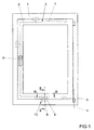
- Figure 1 shows a window with a pivotable against a frame 1 wings 2 and with a drive rod fitting 3 for selectively moving the wing 2 in a closed position in which the wing 2 is locked in the frame 1 or in a rotational position in which the wing. 2 about a vertical axis 4 of the frame 1 is pivotally away or in a tilted position in which the wing 2 about a horizontal axis 5 relative to the frame 1 is pivotable.
- the drive rod fitting 3 has a drive rod 7 longitudinally displaceable by a handle 6.
- On the drive rod 7 a plurality of locking pins 8 are fixed, which fastened on the frame 1 strike plates. 9 face.
- the locking pin 8 form with the striking plates 9 each have a closure 10 with which the espagnolette fitting 3 is adjustable for the described positions.
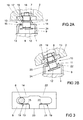
- FIG. 2 a shows a sectional illustration through a closure 10 arranged on the horizontally lower spars of the frame 1 and of the wing 2 in the closed position in which the wing 2 is locked in the frame 1.
- the locking pin 8 is formed as a well-known mushroom head with a arranged at a free end of a shaft 11 radial widening 12.
- the striking plate 9 has two webs 13, 14 arranged transversely to the longitudinal axis of the lock pin 8.
- the front, in the opening direction of the wing 2 shown in Figure 1 facing web 13 has a guide 15 for supporting the shank 11 of the locking pin 8 in the illustrated tilted position.
- the rear web 14 has a smaller wall thickness than the guide 15 having web 13.
- the small wall thickness of a web 14 is generated by a deformation, for example in the extrusion process.
- the upper edges of the webs 13, 14 are arranged at a height. Due to the small wall thickness, the underside of the rear web 14 has a greater distance to a contact surface of the striking plate 9 on the frame 1 as the front web 13.
- the two webs 13, 14 engage over the radial widening 12 of the shaft 11 of the locking pin 8.
- the locking pin 8 is fixed with a foot 16 on the drive rod 7 of the espagnolette fitting 3 and penetrates a fixed in the wing 2 forend plate 17 in the region of a slot 18. Furthermore, the guide 15 having web 13 on its side facing away from the frame 1 a chamfer 19th
- FIG. 2b shows the closure 10 from FIG. 2a in a tilted position, in which the wing 2 is tilted about the horizontal axis 5 shown in FIG.
- the tilting is carried out by a drive of the locking pin 8 with the drive rod 7 in a second guide 20.
- This guide 20 has as the guide described in Figure 2a a locking pin 8 supporting web 21 and a rear web 22.
- the front, the locking pin 8 supporting The web 21 has the chamfer 19, while the rear web 22 has a small wall thickness.
- the small wall thickness and the chamfer 19 allow a pivoting of the locking pin 8 and thus also of the wing 2 by a particularly large angular range. Furthermore, the radial widening 12 of the locking pin 8 has a flank 24 which is inclined away from the drive rod 7 and which faces the underside of the rear web 22. This flank 24 leads to a further enlargement of the possible tilting region of the locking pin 8 with respect to the striking plate 9.
- Figure 3 shows in a sectional view through the window of Figure 1, the position of the locking pin 8 in the striking plate 9 in the closed position.
- the strike plate 9 is constructed symmetrically and can therefore be used both for the illustrated in Figure 1, left-hinged window and right-hinged window.
Landscapes
- Engineering & Computer Science (AREA)
- Mechanical Engineering (AREA)
- Lock And Its Accessories (AREA)
- Table Devices Or Equipment (AREA)
- Stringed Musical Instruments (AREA)
- Window Of Vehicle (AREA)
- Helmets And Other Head Coverings (AREA)
- Specific Sealing Or Ventilating Devices For Doors And Windows (AREA)
- Wing Frames And Configurations (AREA)
- Cleaning Implements For Floors, Carpets, Furniture, Walls, And The Like (AREA)
Abstract
Description
- Die Erfindung betrifft ein Schließblech für einen Treibstangenbeschlag für einen gegen einen Rahmen schwenkbaren Flügel eines Fensters einer Fenstertür oder dergleichen mit einer ersten Führung für einen auf einer Treibstange angeordneten Schließzapfen eines Verschlusses in einer Schließstellung, in der der Flügel in dem Rahmen verriegelt ist, und mit einer zweiten Führung für den Schließzapfen in einer Kippstellung, in der der Flügel von dem Rahmen weg kippbar ist, und mit einer Ausnehmung, in der der Schließzapfen in Drehstellung des Flügels in das Schließblech hinein bewegbar ist, wobei die Führungen jeweils einen vorderen, den Schließzapfen in Schließstellung oder Kippstellung abstützenden Steg und einen hinteren Steg aufweisen und wobei die Stege quer zur vorgesehenen Längsachse des Schließzapfens angeordnet sind. Weiterhin betrifft die Erfindung einen Treibstangenbeschlag mit einem solchen Schließblech für ein gegen einen Rahmen schwenkbaren Flügel aufweisendes Fenster, bei dem der Schließzapfen an einer längsverschieblichen Treibstange angeordnet ist und die Führungen parallel zu der Treibstange angeordnet sind.
- Treibstangenbeschläge zur Verriegelung eines Flügels eines Fensters in einem Rahmen weisen in der Regel mehrere Verschlüsse auf. Die Verschlüsse haben auf der Treibstange befestigte Schließzapfen, welche an dem jeweils gegenüberliegenden Bauteil angeordneten Schließblechen gegenüberstehen. In Abhängigkeit von der Stellung der Treibstange vermögen die Verschlüsse einen Formschluss der Schließzapfen mit den Schließblechen zu ermöglichen, indem die Schließzapfen mit einem zylindrischen Schaft in Schließstellung oder in einer Kippstellung in nutförmige Taschen der Schließbleche eindringen. Wenn der Schließzapfen und das Schließblech beispielsweise in den unteren horizontalen Holmen des Flügels und des Rahmens angeordnet sind, besteht in der Kippstellung des Treibstangenbeschlages das Problem, dass der Schließzapfen gegenüber dem Schließblech ebenfalls gekippt wird. Das Schließblech benötigt daher für die Kippstellung eine breitere Ausnehmung zur Aufnahme des Schließzapfens als für eine Schließstellung, in der der Schließzapfen fest mit dem Schließblech verbunden sein muss. In der Praxis wird daher ein asymmetrisches Schließblech eingesetzt. Nachteilig hierbei ist jedoch, dass für rechts anschlagende Flügel ein anderes Schließblech bereitgestellt werden muss als für links anschlagende Flügel, weil sich die Bewegungsrichtung der Treibstange bei der Umrüstung des Treibstangenbeschlages von rechts anschlagenden Fenster auf links anschlagenden Fenster umdreht.
- Aus der DE 199 23 663 A1 ist ein Dreh-/Kippbeschlag bekannt geworden, bei dem das Schließblech zwei spiegelbildlich zueinander angeordnete Taschen zur Aufnahme des Schließzapfens aufweist. Bei rechts anschlagenden Flügeln kann damit die eine Tasche und bei links anschlagenden Flügeln die andere Tasche dem Schließzapfen gegenüberstehend montiert werden. Die Ausnehmungen zur Aufnahme des Schließzapfens in Kippstellung sind dabei größer als die Ausnehmungen zur Aufnahme des Schließzapfens in Schließstellung. Dieses Schließblech ist jedoch sehr kostenintensiv zu fertigen und erhöht zudem die Gefahr einer fehlerhaften Montage. Zudem ist das Schließblech sehr lang gestaltet und erfordert hierdurch eine besonders hohe Anzahl an Befestigungsstellen an dem Rahmen.
- Der Erfindung liegt das Problem zugrunde, ein Schließblech der eingangs genannten Art so auszubilden, dass es bei rechts und links anschlagenden Flügeln einsetzbar und besonders kostengünstig zu fertigen ist. Weiterhin liegt der Erfindung das Problem zugrunde, einen Treibstangenbeschlag mit einem solchen Schließblech zu schaffen, welcher für rechts und links anschlagende Flügel eine besonders geringe Anzahl an vorrätig zu haltenden Bauteilen benötigt und einen großen Schwenkbereich in Kippstellung ermöglicht.
- Das erstgenannte Problem wird erfindungsgemäß dadurch gelöst, dass die Unterseiten des vorderen und des hinteren Steges zueinander versetzt sind und dass die Unterseite des hinteren Steges weiter von einer Anlagefläche an dem Fenster entfernt ist als die Unterseite des vorderen Steges.
- Durch diese Gestaltung wird eine Behinderung des Schwenkbereichs des Schließzapfens durch den hinteren Steg weitgehend vermieden. Da der vordere Steg jedoch besonders stabil gefertigt sein kann, setzt das erfindungsgemäße Schließblech einem Aufbruchsversuch einen besonders hohen Widerstand entgegen. Die Stege vermögen daher den Schließzapfen sowohl in der Kippstellung als auch in der Schließstellung aufzunehmen. Daher lässt sich das Schließblech für die Aufnahme des Schließzapfens in Schließstellung und in Kippstellung gleich aufbauen. Hierdurch kann ein einziges erfindungsgemäßes Schließblech wahlweise für rechts anschlagende Fenster und für links anschlagende Fenster eingesetzt werden. Das erfindungsgemäße Schließblech erfordert keine überflüssigen Taschen oder dergleichen und lässt sich daher besonders kostengünstig fertigen.
- Der hintere Steg könnte beispielsweise höher sein als der vordere Steg. Dies führt jedoch im montierten Zustand des Schließblechs zu einer Verengung des Spaltes zwischen dem Flügel und dem Rahmen und damit im ungünstigsten Fall zu einem Klemmen des Flügels. Ein Klemmen des Flügels lässt sich gemäß einer vorteilhaften Weiterbildung der Erfindung einfach vermeiden, wenn der hintere der beiden Stege an seinem dem gegenüberliegenden vorderen Steg zugewandten Rand eine geringere Wandstärke aufweist als der vordere Steg.
- Zur Erzeugung der geringen Wandstärke der hinteren Führung könnte der hintere Steg im Querschnitt keilförmig gestaltet sein. Häufig weisen Schließzapfen jedoch an ihrem freien Ende radiale Verbreiterungen auf, welche von den Stegen hintergriffen werden können. Ein solcher Treibstangenbeschlag weist hierdurch eine besonders hohe Einbruchssicherheit auf. Ein keilförmiger Querschnitt des hinteren Steges könnte bei einem solchen Treibstangenbeschlag jedoch den möglichen Kippbereich des Schließzapfens beschränken, wenn die radiale Verbreiterung gegen einen Bereich mit hoher Wandstärke des hinteren Steges gelangt. Eine Beeinträchtigung des Kippbereichs des Schließzapfens lässt sich jedoch gemäß einer vorteilhaften Weiterbildung der Erfindung einfach vermeiden, wenn die vorderen, die Führungen aufweisenden Stege jeweils eine konstante Wandstärke aufweisen, wobei die Wandstärke des hinteren Steges geringer ist als die Wandstärke des vorderen Steges.
- Zur weiteren Erhöhung des Kippbereichs des Schließzapfens trägt es gemäß einer vorteilhaften Weiterbildung der Erfindung bei, wenn der vordere Steg eine in Kipprichtung des Schließzapfens weisende Fase hat.
- Das erfindungsgemäße Schließblech hat eine besonders hohe Stabilität und lässt sich besonders kostengünstig fertigen, wenn die geringe Wandstärke des hinteren Steges durch eine Querschnittsverjüngung eines das Schließblech erzeugenden Blechs mit einer dem vorderen Steg entsprechenden Wandstärke erzeugt ist.
- Das zweitgenannte Problem, nämlich die Schaffung eines Treibstangenbeschlages mit einem genannten Schließblech, welcher für rechts und links anschlagende Flügel eine besonders geringe Anzahl an vorrätig zu haltenden Bauteilen benötigt und einen großen Schwenkbereich in Kippstellung ermöglicht, wird erfindungsgemäß dadurch gelöst, dass die radiale Verbreiterung des Schließzapfens eine von der Treibstange weg geneigte, der Unterseite des hinteren Steges in Kippstellung im Wesentlichen parallel gegenüberstehende Flanke hat.
- Durch diese Gestaltung wird eine Behinderung des Schwenkbereichs in Kipprichtung durch die radiale Verbreiterung des Schließzapfens besonders gering gehalten, da der Schließzapfen mit seiner geneigten Flanke der radialen Verbreiterung der Unterseite des hinteren Steges gegenübersteht. In Schließstellung setzt der Treibstangenbeschlag einem Aufbruchsversuch jedoch einen besonders hohen Widerstand entgegen, da die radiale Verbreiterung von den Stegen hintergriffen wird. Daher können die den Schließzapfen abstützenden Stege in Kippstellung und in Schließstellung gleich aufgebaut sein. Der Treibstangenbeschlag erfordert hierdurch besonders wenige, vorrätig zu haltende Bauteile.
- Die Erfindung lässt zahlreiche Ausführungsformen zu. Zur weiteren Verdeutlichung ihres Grundprinzips ist eine davon in der Zeichnung dargestellt und wird nachfolgend beschrieben. Diese zeigt in
- Fig. 1
- ein Fenster mit einem ein erfindungsgemäßes Schließblech aufweisenden Treibstangenbeschlag,
- Fig. 2a
- eine Schnittdarstellung durch das Fenster aus Figur 1 entlang der Linie II - II in Schließstellung,
- Fig. 2b
- eine Schnittdarstellung durch das Fenster aus Figur 1 in Kippstellung,
- Fig. 3
- eine Schnittdarstellung durch das Fenster aus Figur 1 entlang der Linie III - III.
- Figur 1 zeigt ein Fenster mit einem gegen einen Rahmen 1 schwenkbaren Flügel 2 und mit einem Treibstangenbeschlag 3 zum wahlweisen Bewegen des Flügels 2 in eine Schließstellung, in der der Flügel 2 in dem Rahmen 1 verriegelt ist oder in eine Drehstellung, in der der Flügel 2 um eine vertikale Achse 4 von dem Rahmen 1 weg schwenkbar ist oder in eine Kippstellung, in der der Flügel 2 um eine horizontale Achse 5 gegenüber dem Rahmen 1 verschwenkbar ist. Der Treibstangenbeschlag 3 weist eine von einer Handhabe 6 längsverschiebliche Treibstange 7 auf. Auf der Treibstange 7 sind mehrere Schließzapfen 8 befestigt, welche auf dem Rahmen 1 befestigten Schließblechen 9 gegenüberstehen. Die Schließzapfen 8 bilden mit den Schließblechen 9 jeweils einen Verschluss 10, mit denen der Treibstangenbeschlag 3 für die beschriebenen Stellungen verstellbar ist.
- Figur 2a zeigt eine Schnittdarstellung durch einen an den horizontal unteren Holmen des Rahmens 1 und des Flügels 2 angeordneten Verschluss 10 in der Schließstellung, in der der Flügel 2 in dem Rahmen 1 verriegelt ist. Der Schließzapfen 8 ist als allgemein bekannter Pilzkopf mit einer an einem freien Ende eines Schaftes 11 angeordneten radialen Verbreiterung 12 ausgebildet. Das Schließblech 9 weist zwei quer zur Längsachse des Schließzapfens 8 angeordnete Stege 13, 14 auf. Der vordere, in Öffnungsrichtung des in Figur 1 dargestellten Flügels 2 weisende Steg 13 hat eine Führung 15 zur Abstützung des Schaftes 11 des Schließzapfens 8 in der dargestellten Kippstellung. Der hintere Steg 14 hat eine geringere Wandstärke als der die Führung 15 aufweisende Steg 13. Die geringe Wandstärke des einen Steges 14 ist durch eine Verformung, beispielsweise im Fließpressverfahren erzeugt. Die Oberkanten der Stege 13, 14 sind auf einer Höhe angeordnet. Durch die geringe Wandstärke hat die Unterseite des hinteren Steges 14 einen größeren Abstand zu einer Anlagefläche des Schließblechs 9 an dem Rahmen 1 als der vordere Steg 13. Die beiden Stege 13, 14 übergreifen die radiale Verbreiterung 12 des Schaftes 11 des Schließzapfens 8. Der Schließzapfen 8 ist mit einem Fuß 16 auf der Treibstange 7 des Treibstangenbeschlages 3 befestigt und durchdringt eine im Flügel 2 befestigte Stulpschiene 17 im Bereich eines Langlochs 18. Weiterhin hat der die Führung 15 aufweisende Steg 13 an seiner dem Rahmen 1 abgewandten Seite eine Fase 19.
- Figur 2b zeigt den Verschluss 10 aus Figur 2a in einer Kippstellung, in der der Flügel 2 um die in Figur 1 dargestellte horizontale Achse 5 gekippt ist. Das Kippen erfolgt durch einen Antrieb des Schließzapfens 8 mit der Treibstange 7 in eine zweite Führung 20. Diese Führung 20 hat wie die in Figur 2a beschriebene Führung einen den Schließzapfen 8 abstützenden Steg 21 und einen hinteren Steg 22. Der vordere, den Schließzapfen 8 abstützende Steg 21 weist die Fase 19 auf, während der hintere Steg 22 eine geringe Wandstärke hat. Beim Kippen des Flügels 2 wird der Schließzapfen 8 auf die Fase 19 des einen Steges 21 hin verschwenkt. Gleichzeitig wird die radiale Verbreiterung 12 des Schließzapfens 8 in Richtung der Unterseite des die geringe Wandstärke aufweisenden Steges 22 verschwenkt. Die geringe Wandstärke und die Fase 19 ermöglichen eine Verschwenkung des Schließzapfens 8 und damit auch des Flügels 2 um einen besonders großen Winkelbereich. Weiterhin weist die radiale Verbreiterung 12 des Schließzapfens 8 eine von der Treibstange 7 weg geneigte Flanke 24 auf, welche der Unterseite des hinteren Steges 22 gegenübersteht. Diese Flanke 24 führt zu einer weiteren Vergrößerung des möglichen Kippbereichs des Schließzapfens 8 gegenüber dem Schließblech 9.
- Figur 3 zeigt in einer Schnittdarstellung durch das Fenster aus Figur 1 die Stellung des Schließzapfens 8 im Schließblech 9 in Schließstellung. In der Drehstellung ist der Schließzapfen 8 im Bereich einer mittigen Ausnehmung 23 im Schließblech 9 angeordnet, während er in Kippstellung an der anderen Führung 20 anliegt. Das Schließblech 9 ist symmetrisch aufgebaut und lässt sich daher sowohl für das in Figur 1 dargestellte, links anschlagende Fenster als auch für rechts anschlagende Fenster einsetzen.
Claims (6)
- Schließblech für einen Treibstangenbeschlag für einen gegen einen Rahmen schwenkbaren Flügel eines Fensters einer Fenstertür oder dergleichen mit einer ersten Führung für einen auf einer Treibstange angeordneten Schließzapfen eines Verschlusses in einer Schließstellung, in der der Flügel in dem Rahmen verriegelt ist, und mit einer zweiten Führung für den Schließzapfen in einer Kippstellung, in der der Flügel von dem Rahmen weg kippbar ist, und mit einer Ausnehmung, in der der Schließzapfen in Drehstellung des Flügels in das Schließblech hinein bewegbar ist, wobei die Führungen jeweils einen vorderen, den Schließzapfen in Schließstellung oder Kippstellung abstützenden Steg und einen hinteren Steg aufweisen, und wobei die Stege quer zur vorgesehenen Längsachse des Schließzapfens angeordnet sind, dadurch gekennzeichnet, dass die Unterseiten des vorderen und des hinteren Steges (13, 14, 21, 22) zueinander versetzt sind und dass die Unterseite des hinteren Steges (14, 22) weiter von einer Anlagefläche an dem Fenster entfernt ist als die Unterseite des vorderen Steges (13, 21).
- Schließblech nach Anspruch 1, dadurch gekennzeichnet, dass der hintere der beiden Stege (14, 22) an seinem dem gegenüberliegenden vorderen Steg (13, 21) zugewandten Rand eine geringere Wandstärke aufweist als der vordere Steg (13, 21).
- Schließblech nach Anspruch 1 oder 2, dadurch gekennzeichnet, dass die vorderen, die Führungen (15, 20) aufweisenden Stege (13, 21) jeweils eine konstante Wandstärke aufweisen, wobei die Wandstärke des hinteren Steges (14, 22) geringer ist als die Wandstärke des vorderen Steges (13, 21).
- Schließblech nach zumindest einem der vorhergehenden Ansprüche, dadurch gekennzeichnet, dass der vordere Steg (13, 21) eine in Kipprichtung des Schließzapfens (8) weisende Fase (19) hat.
- Schließblech nach zumindest einem der vorhergehenden Ansprüche, dadurch gekennzeichnet, dass die geringe Wandstärke des hinteren Steges (14, 22) durch eine Querschnittsverjüngung eines das Schließblech (9) erzeugenden Blechs mit einer dem vorderen Steg (13, 21) entsprechenden Wandstärke erzeugt ist.
- Treibstangenbeschlag mit einem Schließblech nach einem der vorhergehenden Ansprüche für ein gegen einen Rahmen schwenkbaren Flügel aufweisendes Fenster, bei dem der Schließzapfen an einer längsverschieblichen Treibstange angeordnet ist und die Führungen parallel zu der Treibstange angeordnet sind, dadurch gekennzeichnet, dass die radiale Verbreiterung (12) des Schließzapfens (8) eine von der Treibstange (7) weg geneigte, der Unterseite des hinteren Steges (14, 22) in Kippstellung im Wesentlichen parallel gegenüberstehende Flanke (24) hat.
Priority Applications (1)
| Application Number | Priority Date | Filing Date | Title |
|---|---|---|---|
| PL05107494T PL1643063T3 (pl) | 2004-09-29 | 2005-08-16 | Blaszka ryglowa i okucie z prętem nastawczym z blaszką ryglową |
Applications Claiming Priority (1)
| Application Number | Priority Date | Filing Date | Title |
|---|---|---|---|
| DE102004047171A DE102004047171A1 (de) | 2004-09-29 | 2004-09-29 | Schließblech und Treibstangenbeschlag mit einem Schließblech |
Publications (2)
| Publication Number | Publication Date |
|---|---|
| EP1643063A1 true EP1643063A1 (de) | 2006-04-05 |
| EP1643063B1 EP1643063B1 (de) | 2007-06-27 |
Family
ID=35462644
Family Applications (1)
| Application Number | Title | Priority Date | Filing Date |
|---|---|---|---|
| EP05107494A Expired - Lifetime EP1643063B1 (de) | 2004-09-29 | 2005-08-16 | Schließblech und Treibstangenbeschlag mit einem Schließblech |
Country Status (4)
| Country | Link |
|---|---|
| EP (1) | EP1643063B1 (de) |
| AT (1) | ATE365858T1 (de) |
| DE (2) | DE102004047171A1 (de) |
| PL (1) | PL1643063T3 (de) |
Cited By (1)
| Publication number | Priority date | Publication date | Assignee | Title |
|---|---|---|---|---|
| EP2216470A3 (de) * | 2009-02-10 | 2011-09-14 | Aug. Winkhaus GmbH & Co. KG | Verschluss für einen Treibstangenbeschlag |
Citations (4)
| Publication number | Priority date | Publication date | Assignee | Title |
|---|---|---|---|---|
| GB2190704A (en) * | 1986-03-26 | 1987-11-25 | Smith Wallis & Company Limited | Window assemblies |
| DE19923663A1 (de) * | 1998-10-13 | 2000-04-20 | Hautau Gmbh W | Drehkippbeschlag mit Sicherheitsschließplatte |
| DE19909400A1 (de) * | 1999-03-04 | 2000-09-07 | Siegenia Frank Kg | Fenster oder Tür, Beschlag für ein Fenster oder eine Tür, sowie Verfahren zur Herstellung eines Fenster oder einer Tür |
| DE20114422U1 (de) * | 2001-08-31 | 2001-11-08 | Roto Frank Ag, 70771 Leinfelden-Echterdingen | Beschlag an einem Fenster, einer Tür o.dgl. mit einem Riegelzapfen sowie einem Kippverriegelungsteil |
Family Cites Families (4)
| Publication number | Priority date | Publication date | Assignee | Title |
|---|---|---|---|---|
| DE1784674A1 (de) * | 1968-09-04 | 1971-09-09 | Frank Gmbh Wilh | Verschluss fuer einen Fluegel eines Fensters,einer Tuer od.dgl. |
| DE4420312A1 (de) * | 1994-06-10 | 1995-12-14 | Bilstein August Gmbh Co Kg | Dreh-Kipp-Beschlag für Fenster, Türen oder dergleichen |
| DE19605047C2 (de) * | 1995-11-28 | 1998-04-09 | Aubi Baubeschlaege Gmbh | Dreh-Kipp-Beschlag für Fenster, Türen oder dergleichen |
| DE20204115U1 (de) * | 2002-03-14 | 2002-10-17 | Alfred Bohn GmbH & Co. KG, 74889 Sinsheim | Dreh-Kipp-Beschlag für Fenster- o.dgl. -Flügel, insbesondere Kellerfenster und Fenster mit einem solchen Beschlag |
-
2004
- 2004-09-29 DE DE102004047171A patent/DE102004047171A1/de not_active Withdrawn
-
2005
- 2005-08-16 PL PL05107494T patent/PL1643063T3/pl unknown
- 2005-08-16 EP EP05107494A patent/EP1643063B1/de not_active Expired - Lifetime
- 2005-08-16 DE DE502005000929T patent/DE502005000929D1/de not_active Expired - Lifetime
- 2005-08-16 AT AT05107494T patent/ATE365858T1/de active
Patent Citations (4)
| Publication number | Priority date | Publication date | Assignee | Title |
|---|---|---|---|---|
| GB2190704A (en) * | 1986-03-26 | 1987-11-25 | Smith Wallis & Company Limited | Window assemblies |
| DE19923663A1 (de) * | 1998-10-13 | 2000-04-20 | Hautau Gmbh W | Drehkippbeschlag mit Sicherheitsschließplatte |
| DE19909400A1 (de) * | 1999-03-04 | 2000-09-07 | Siegenia Frank Kg | Fenster oder Tür, Beschlag für ein Fenster oder eine Tür, sowie Verfahren zur Herstellung eines Fenster oder einer Tür |
| DE20114422U1 (de) * | 2001-08-31 | 2001-11-08 | Roto Frank Ag, 70771 Leinfelden-Echterdingen | Beschlag an einem Fenster, einer Tür o.dgl. mit einem Riegelzapfen sowie einem Kippverriegelungsteil |
Cited By (1)
| Publication number | Priority date | Publication date | Assignee | Title |
|---|---|---|---|---|
| EP2216470A3 (de) * | 2009-02-10 | 2011-09-14 | Aug. Winkhaus GmbH & Co. KG | Verschluss für einen Treibstangenbeschlag |
Also Published As
| Publication number | Publication date |
|---|---|
| EP1643063B1 (de) | 2007-06-27 |
| DE102004047171A1 (de) | 2006-04-13 |
| DE502005000929D1 (de) | 2007-08-09 |
| ATE365858T1 (de) | 2007-07-15 |
| PL1643063T3 (pl) | 2007-10-31 |
Similar Documents
| Publication | Publication Date | Title |
|---|---|---|
| EP0335069B1 (de) | Flachschlüssel für Zylinderschlösser sowie zugehöriges Zylinderschloss | |
| EP3798390B2 (de) | Faltanlage | |
| EP2206860B1 (de) | Beschlag mit ausfahrbarem Verriegelungselement | |
| EP3795783B1 (de) | Nebenschloss für eine mehrpunktverriegelung | |
| EP2113624B1 (de) | Tür- oder Fenstersicherungsvorrichtung | |
| DE8913826U1 (de) | Verriegelungsvorrichtung für ein Fenster, eine Tür o.dgl. | |
| EP1643063B1 (de) | Schließblech und Treibstangenbeschlag mit einem Schließblech | |
| EP0539908A1 (de) | Einstellbares Schliessblech für eine Tür oder ein Fenster | |
| EP1008713A1 (de) | Verriegelungsvorrichtung | |
| EP4146888B1 (de) | Scharnierbaugruppe mit gemeinsamer betätigung | |
| DE8614557U1 (de) | Verhakungsvorrichtung zwischen dem Flügel und dem feststehenden Rahmen von Fenstern, Türen od.dgl. | |
| EP1493889B1 (de) | Schliessplatte | |
| DE102012218887B4 (de) | Schließstück für ein Fenster, eine Tür oder dergleichen | |
| EP3470606B1 (de) | Verschluss für einen treibstangenbeschlag | |
| EP1010844B1 (de) | Schliessblechvorrichtung für Türschlösser | |
| EP4379173B1 (de) | Schliesszylinder | |
| EP3656955B1 (de) | Schliessteil | |
| EP3374581B1 (de) | Schliessleiste | |
| DE19527418C2 (de) | Fenster, Tür oder dergleichen | |
| EP3101207B1 (de) | Schiebetüranordnung | |
| EP3626920A1 (de) | Riegelschloss | |
| EP2186975B1 (de) | Schlüssel für einen Schließzylinder | |
| EP0625235A1 (de) | Sicherheitstür und sicherheitsvorrichtung zum einbau in eine tür | |
| EP0718457B1 (de) | Beschlagsystem für Schwenk- oder Schwenkkippflügel | |
| DE8803303U1 (de) | Schließblech für Türverschlüsse |
Legal Events
| Date | Code | Title | Description |
|---|---|---|---|
| PUAI | Public reference made under article 153(3) epc to a published international application that has entered the european phase |
Free format text: ORIGINAL CODE: 0009012 |
|
| AK | Designated contracting states |
Kind code of ref document: A1 Designated state(s): AT BE BG CH CY CZ DE DK EE ES FI FR GB GR HU IE IS IT LI LT LU LV MC NL PL PT RO SE SI SK TR |
|
| AX | Request for extension of the european patent |
Extension state: AL BA HR MK YU |
|
| 17P | Request for examination filed |
Effective date: 20060726 |
|
| AKX | Designation fees paid |
Designated state(s): AT BE BG CH CY CZ DE DK EE ES FI FR GB GR HU IE IS IT LI LT LU LV MC NL PL PT RO SE SI SK TR |
|
| GRAP | Despatch of communication of intention to grant a patent |
Free format text: ORIGINAL CODE: EPIDOSNIGR1 |
|
| RIN1 | Information on inventor provided before grant (corrected) |
Inventor name: LUKAS, TORSTEN |
|
| GRAS | Grant fee paid |
Free format text: ORIGINAL CODE: EPIDOSNIGR3 |
|
| GRAA | (expected) grant |
Free format text: ORIGINAL CODE: 0009210 |
|
| AK | Designated contracting states |
Kind code of ref document: B1 Designated state(s): AT BE BG CH CY CZ DE DK EE ES FI FR GB GR HU IE IS IT LI LT LU LV MC NL PL PT RO SE SI SK TR |
|
| REG | Reference to a national code |
Ref country code: GB Ref legal event code: FG4D Free format text: NOT ENGLISH |
|
| REG | Reference to a national code |
Ref country code: CH Ref legal event code: EP |
|
| REG | Reference to a national code |
Ref country code: IE Ref legal event code: FG4D Free format text: LANGUAGE OF EP DOCUMENT: GERMAN |
|
| REF | Corresponds to: |
Ref document number: 502005000929 Country of ref document: DE Date of ref document: 20070809 Kind code of ref document: P |
|
| REG | Reference to a national code |
Ref country code: RO Ref legal event code: EPE |
|
| PG25 | Lapsed in a contracting state [announced via postgrant information from national office to epo] |
Ref country code: SE Free format text: LAPSE BECAUSE OF FAILURE TO SUBMIT A TRANSLATION OF THE DESCRIPTION OR TO PAY THE FEE WITHIN THE PRESCRIBED TIME-LIMIT Effective date: 20070927 |
|
| REG | Reference to a national code |
Ref country code: PL Ref legal event code: T3 |
|
| ET | Fr: translation filed | ||
| NLV1 | Nl: lapsed or annulled due to failure to fulfill the requirements of art. 29p and 29m of the patents act | ||
| GBV | Gb: ep patent (uk) treated as always having been void in accordance with gb section 77(7)/1977 [no translation filed] |
Effective date: 20070627 |
|
| REG | Reference to a national code |
Ref country code: IE Ref legal event code: FD4D |
|
| PG25 | Lapsed in a contracting state [announced via postgrant information from national office to epo] |
Ref country code: ES Free format text: LAPSE BECAUSE OF FAILURE TO SUBMIT A TRANSLATION OF THE DESCRIPTION OR TO PAY THE FEE WITHIN THE PRESCRIBED TIME-LIMIT Effective date: 20071008 Ref country code: CZ Free format text: LAPSE BECAUSE OF FAILURE TO SUBMIT A TRANSLATION OF THE DESCRIPTION OR TO PAY THE FEE WITHIN THE PRESCRIBED TIME-LIMIT Effective date: 20070627 Ref country code: LT Free format text: LAPSE BECAUSE OF FAILURE TO SUBMIT A TRANSLATION OF THE DESCRIPTION OR TO PAY THE FEE WITHIN THE PRESCRIBED TIME-LIMIT Effective date: 20070627 Ref country code: BG Free format text: LAPSE BECAUSE OF FAILURE TO SUBMIT A TRANSLATION OF THE DESCRIPTION OR TO PAY THE FEE WITHIN THE PRESCRIBED TIME-LIMIT Effective date: 20070927 Ref country code: SI Free format text: LAPSE BECAUSE OF FAILURE TO SUBMIT A TRANSLATION OF THE DESCRIPTION OR TO PAY THE FEE WITHIN THE PRESCRIBED TIME-LIMIT Effective date: 20070627 Ref country code: IE Free format text: LAPSE BECAUSE OF FAILURE TO SUBMIT A TRANSLATION OF THE DESCRIPTION OR TO PAY THE FEE WITHIN THE PRESCRIBED TIME-LIMIT Effective date: 20070627 Ref country code: IS Free format text: LAPSE BECAUSE OF FAILURE TO SUBMIT A TRANSLATION OF THE DESCRIPTION OR TO PAY THE FEE WITHIN THE PRESCRIBED TIME-LIMIT Effective date: 20071027 Ref country code: PT Free format text: LAPSE BECAUSE OF FAILURE TO SUBMIT A TRANSLATION OF THE DESCRIPTION OR TO PAY THE FEE WITHIN THE PRESCRIBED TIME-LIMIT Effective date: 20071127 Ref country code: NL Free format text: LAPSE BECAUSE OF FAILURE TO SUBMIT A TRANSLATION OF THE DESCRIPTION OR TO PAY THE FEE WITHIN THE PRESCRIBED TIME-LIMIT Effective date: 20070627 |
|
| BERE | Be: lapsed |
Owner name: AUG. WINKHAUS G.M.B.H. & CO. KG Effective date: 20070831 |
|
| PG25 | Lapsed in a contracting state [announced via postgrant information from national office to epo] |
Ref country code: SK Free format text: LAPSE BECAUSE OF FAILURE TO SUBMIT A TRANSLATION OF THE DESCRIPTION OR TO PAY THE FEE WITHIN THE PRESCRIBED TIME-LIMIT Effective date: 20070627 Ref country code: LV Free format text: LAPSE BECAUSE OF FAILURE TO SUBMIT A TRANSLATION OF THE DESCRIPTION OR TO PAY THE FEE WITHIN THE PRESCRIBED TIME-LIMIT Effective date: 20070627 |
|
| PG25 | Lapsed in a contracting state [announced via postgrant information from national office to epo] |
Ref country code: DK Free format text: LAPSE BECAUSE OF FAILURE TO SUBMIT A TRANSLATION OF THE DESCRIPTION OR TO PAY THE FEE WITHIN THE PRESCRIBED TIME-LIMIT Effective date: 20070627 Ref country code: GR Free format text: LAPSE BECAUSE OF FAILURE TO SUBMIT A TRANSLATION OF THE DESCRIPTION OR TO PAY THE FEE WITHIN THE PRESCRIBED TIME-LIMIT Effective date: 20070928 Ref country code: IT Free format text: LAPSE BECAUSE OF FAILURE TO SUBMIT A TRANSLATION OF THE DESCRIPTION OR TO PAY THE FEE WITHIN THE PRESCRIBED TIME-LIMIT Effective date: 20070627 Ref country code: MC Free format text: LAPSE BECAUSE OF NON-PAYMENT OF DUE FEES Effective date: 20070831 |
|
| PLBE | No opposition filed within time limit |
Free format text: ORIGINAL CODE: 0009261 |
|
| STAA | Information on the status of an ep patent application or granted ep patent |
Free format text: STATUS: NO OPPOSITION FILED WITHIN TIME LIMIT |
|
| PG25 | Lapsed in a contracting state [announced via postgrant information from national office to epo] |
Ref country code: GB Free format text: LAPSE BECAUSE OF FAILURE TO SUBMIT A TRANSLATION OF THE DESCRIPTION OR TO PAY THE FEE WITHIN THE PRESCRIBED TIME-LIMIT Effective date: 20070627 |
|
| 26N | No opposition filed |
Effective date: 20080328 |
|
| PG25 | Lapsed in a contracting state [announced via postgrant information from national office to epo] |
Ref country code: BE Free format text: LAPSE BECAUSE OF NON-PAYMENT OF DUE FEES Effective date: 20070831 |
|
| PG25 | Lapsed in a contracting state [announced via postgrant information from national office to epo] |
Ref country code: EE Free format text: LAPSE BECAUSE OF FAILURE TO SUBMIT A TRANSLATION OF THE DESCRIPTION OR TO PAY THE FEE WITHIN THE PRESCRIBED TIME-LIMIT Effective date: 20070627 |
|
| PG25 | Lapsed in a contracting state [announced via postgrant information from national office to epo] |
Ref country code: FI Free format text: LAPSE BECAUSE OF FAILURE TO SUBMIT A TRANSLATION OF THE DESCRIPTION OR TO PAY THE FEE WITHIN THE PRESCRIBED TIME-LIMIT Effective date: 20070627 |
|
| PG25 | Lapsed in a contracting state [announced via postgrant information from national office to epo] |
Ref country code: CY Free format text: LAPSE BECAUSE OF FAILURE TO SUBMIT A TRANSLATION OF THE DESCRIPTION OR TO PAY THE FEE WITHIN THE PRESCRIBED TIME-LIMIT Effective date: 20070627 |
|
| PG25 | Lapsed in a contracting state [announced via postgrant information from national office to epo] |
Ref country code: LU Free format text: LAPSE BECAUSE OF NON-PAYMENT OF DUE FEES Effective date: 20070816 |
|
| PG25 | Lapsed in a contracting state [announced via postgrant information from national office to epo] |
Ref country code: HU Free format text: LAPSE BECAUSE OF FAILURE TO SUBMIT A TRANSLATION OF THE DESCRIPTION OR TO PAY THE FEE WITHIN THE PRESCRIBED TIME-LIMIT Effective date: 20071228 Ref country code: TR Free format text: LAPSE BECAUSE OF FAILURE TO SUBMIT A TRANSLATION OF THE DESCRIPTION OR TO PAY THE FEE WITHIN THE PRESCRIBED TIME-LIMIT Effective date: 20070627 |
|
| REG | Reference to a national code |
Ref country code: CH Ref legal event code: PL |
|
| PG25 | Lapsed in a contracting state [announced via postgrant information from national office to epo] |
Ref country code: LI Free format text: LAPSE BECAUSE OF NON-PAYMENT OF DUE FEES Effective date: 20090831 Ref country code: CH Free format text: LAPSE BECAUSE OF NON-PAYMENT OF DUE FEES Effective date: 20090831 |
|
| PGFP | Annual fee paid to national office [announced via postgrant information from national office to epo] |
Ref country code: TR Payment date: 20110816 Year of fee payment: 7 Ref country code: RO Payment date: 20110801 Year of fee payment: 7 |
|
| PGFP | Annual fee paid to national office [announced via postgrant information from national office to epo] |
Ref country code: PL Payment date: 20120806 Year of fee payment: 8 |
|
| PGFP | Annual fee paid to national office [announced via postgrant information from national office to epo] |
Ref country code: FR Payment date: 20120903 Year of fee payment: 8 |
|
| PGFP | Annual fee paid to national office [announced via postgrant information from national office to epo] |
Ref country code: DE Payment date: 20121001 Year of fee payment: 8 |
|
| PGFP | Annual fee paid to national office [announced via postgrant information from national office to epo] |
Ref country code: AT Payment date: 20120830 Year of fee payment: 8 |
|
| PG25 | Lapsed in a contracting state [announced via postgrant information from national office to epo] |
Ref country code: RO Free format text: LAPSE BECAUSE OF NON-PAYMENT OF DUE FEES Effective date: 20120816 |
|
| PG25 | Lapsed in a contracting state [announced via postgrant information from national office to epo] |
Ref country code: TR Free format text: LAPSE BECAUSE OF FAILURE TO SUBMIT A TRANSLATION OF THE DESCRIPTION OR TO PAY THE FEE WITHIN THE PRESCRIBED TIME-LIMIT Effective date: 20120816 |
|
| REG | Reference to a national code |
Ref country code: AT Ref legal event code: MM01 Ref document number: 365858 Country of ref document: AT Kind code of ref document: T Effective date: 20130816 |
|
| PG25 | Lapsed in a contracting state [announced via postgrant information from national office to epo] |
Ref country code: DE Free format text: LAPSE BECAUSE OF NON-PAYMENT OF DUE FEES Effective date: 20140301 |
|
| REG | Reference to a national code |
Ref country code: DE Ref legal event code: R119 Ref document number: 502005000929 Country of ref document: DE Effective date: 20140301 |
|
| REG | Reference to a national code |
Ref country code: FR Ref legal event code: ST Effective date: 20140430 |
|
| PG25 | Lapsed in a contracting state [announced via postgrant information from national office to epo] |
Ref country code: AT Free format text: LAPSE BECAUSE OF NON-PAYMENT OF DUE FEES Effective date: 20130816 |
|
| PG25 | Lapsed in a contracting state [announced via postgrant information from national office to epo] |
Ref country code: FR Free format text: LAPSE BECAUSE OF NON-PAYMENT OF DUE FEES Effective date: 20130902 |
|
| PG25 | Lapsed in a contracting state [announced via postgrant information from national office to epo] |
Ref country code: PL Free format text: LAPSE BECAUSE OF NON-PAYMENT OF DUE FEES Effective date: 20130816 |
|
| REG | Reference to a national code |
Ref country code: PL Ref legal event code: LAPE |