EP1642717B1 - Vorrichtung zur Reinigung von Walzenoberflächen in Druckmaschinen - Google Patents
Vorrichtung zur Reinigung von Walzenoberflächen in Druckmaschinen Download PDFInfo
- Publication number
- EP1642717B1 EP1642717B1 EP20050019600 EP05019600A EP1642717B1 EP 1642717 B1 EP1642717 B1 EP 1642717B1 EP 20050019600 EP20050019600 EP 20050019600 EP 05019600 A EP05019600 A EP 05019600A EP 1642717 B1 EP1642717 B1 EP 1642717B1
- Authority
- EP
- European Patent Office
- Prior art keywords
- supply line
- collecting container
- compressed air
- detergent
- water
- Prior art date
- Legal status (The legal status is an assumption and is not a legal conclusion. Google has not performed a legal analysis and makes no representation as to the accuracy of the status listed.)
- Revoked
Links
- 238000004140 cleaning Methods 0.000 title claims description 8
- XLYOFNOQVPJJNP-UHFFFAOYSA-N water Substances O XLYOFNOQVPJJNP-UHFFFAOYSA-N 0.000 claims description 15
- 239000003599 detergent Substances 0.000 claims description 12
- 238000005507 spraying Methods 0.000 claims description 12
- 239000007921 spray Substances 0.000 claims description 11
- 239000000203 mixture Substances 0.000 claims description 8
- 238000011144 upstream manufacturing Methods 0.000 claims description 3
- 238000007654 immersion Methods 0.000 claims 1
- 239000012459 cleaning agent Substances 0.000 description 12
- 239000007788 liquid Substances 0.000 description 12
- 239000000443 aerosol Substances 0.000 description 2
- 239000004744 fabric Substances 0.000 description 2
- 238000000034 method Methods 0.000 description 2
- 239000003595 mist Substances 0.000 description 2
- 230000002411 adverse Effects 0.000 description 1
- 230000015572 biosynthetic process Effects 0.000 description 1
- 238000010276 construction Methods 0.000 description 1
- 230000000994 depressogenic effect Effects 0.000 description 1
- 230000000694 effects Effects 0.000 description 1
- 239000003973 paint Substances 0.000 description 1
- 230000035515 penetration Effects 0.000 description 1
- 238000003825 pressing Methods 0.000 description 1
- 238000009827 uniform distribution Methods 0.000 description 1
- 238000009736 wetting Methods 0.000 description 1
Images


Classifications
-
- B—PERFORMING OPERATIONS; TRANSPORTING
- B41—PRINTING; LINING MACHINES; TYPEWRITERS; STAMPS
- B41F—PRINTING MACHINES OR PRESSES
- B41F35/00—Cleaning arrangements or devices
- B41F35/06—Cleaning arrangements or devices for offset cylinders
Definitions
- the invention relates to a device for cleaning roll surfaces in printing presses with supply means for introducing water and / or cleaning agent in a common supply line to a spraying device for spraying water, detergent or a water-cleaning agent mixture on a roll surface, with a compressed air source for compressed air for pressing out the cleaning agent from the spraying device, which is connected to the supply line
- Such a device is from the document EP-A1-0 570 763 known.
- the US 5,303,652 A describes a cleaning system of the type mentioned with a spray bar, which has a larger number of spray nozzles and is connected to a supply line for a water-detergent mixture.
- This supply line can be acted upon with compressed air for squeezing the mixture.
- a disadvantage of this known system is that when introducing compressed air, the liquid cleaning agent mixture can be torn into an aerosol or mist. Thus, the uniform distribution of the liquid fraction on the roll surface is largely impossible. This is particularly regrettable because the control of the liquid delivery using compressed air is basically advantageous because it allows cost-effective solutions.
- the invention has for its object to provide a device of the above type, which makes it possible to squeeze the detergent by means of compressed air from the spray device, without causing the adverse aerosol or mist formation.
- the device according to the invention is characterized in that in the supply line, a collecting container is turned on and that the compressed air supply takes place on the upstream side of the collecting container.
- the collecting container thus forms part of the supply line.
- the collecting container has the advantage that when applying compressed air, a closed liquid block can be advanced in the direction of the spraying device and the compressed air is not introduced into the incoming liquid stream.
- the collecting container in the shortest possible distance before the spraying device and to keep the said liquid block as closed as possible in this way.
- the collecting container can also be attached directly to the spraying device.
- the inlet and outlet of the collecting container are higher than the collecting area of the container, so that accumulated liquid can flow to neither one side nor the other.
- the outlet is preferably preceded by a dip tube, so that when injecting compressed air into the sump a closed water column can be squeezed directly through the dip tube and the other part of the supply line.
- the collecting container is formed by a lowered portion of the supply line itself.
- the lowered portion of the supply line may be in the form of a loop or a helix.
- the volume of the collection container should be such that the entire cleaning agent needed for the spraying process can be accommodated. Since the cleaning agent is collected in a closed volume or block at a short distance in front of the spraying device, due to the short time of the action of the compressed air, there is no significant penetration of the compressed air into the liquid volume. The cleaning agent is advanced evenly without air inclusions and pushed out of the nozzles of the spray device. Because of the uniform wetting of the surface to be cleaned, the amount of cleaning agent used can be reduced. On the other hand, a uniform cleaning effect is ensured.
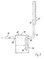
- Fig. 1 The illustration of Fig. 1 is limited to the parts of interest here. Shown is a spray device 10 with a number of nozzles 12. The spray device 10 is supplied through a supply line 14 with a mixture of water and detergent. To the right of the spraying device 10 would be in practice a surface to be sprayed, for example a pressure roller.
- a collecting container 16 is turned on, which is formed in the first embodiment by a line section of the supply line 14. This line section is located below the portion of the supply line 14, in which the collecting container 16 is integrated. Therefore, the collecting container can receive and accumulate the cleaning agent without draining via the supply line 14.
- the depressed portion of the supply conduit 14 is in the form of a coil or loop 18.
- the supply conduit is circularly bent in the region of the collection container. In this section bent into a loop 18, feed lines 20, 22 for water and cleaning agent enter.
- the loop is filled to about 2/3 with liquid.
- compressed air is now supplied in the direction of the arrow 24, the water column collected in the loop 18 is pressed as a continuous block in the direction of the spray device 10 and the nozzles 12. Since the collection container 16 is located immediately in front of the spray device 10, the mentioned water column is only slightly torn by the compressed air.
- Fig. 2 illustrates a spraying process.
- a sequence of unsigned arrows in the supply line 14 and the loop 18 illustrates the movement of the water column or compressed air contained in the loop 18.
- Fig. 3 shows a second embodiment of the invention in a schematic view.
- the collecting container is designated in this case with 26. It is a container of any geometry.
- the container 26 shown is cylindrical, for example. This container is arranged with its larger part lower than the supply line 14, so that the accumulated liquid can not flow off via the supply line 14.
- the supply line 14 is interrupted and connected via an inlet 28 and an outlet 30 to the sump 26. About feed lines 32,34 water and cleaning agents can be initiated. Compressed air can also be supplied in this case via the downstream region of the supply line 14, but optionally also via a separate connection to the collecting container 26th
- the outlet 30 and the downstream portion of the supply line 14 is preceded by a dip tube 36, which extends to below the unnamed liquid level in the reservoir 26.
Landscapes
- Cleaning By Liquid Or Steam (AREA)
- Inking, Control Or Cleaning Of Printing Machines (AREA)
Description
- Die Erfindung betrifft eine Vorrichtung zur Reinigung von Walzenoberflächen in Druckmaschinen mit Zufuhreinrichtungen zum Einleiten von Wasser und/oder Reinigungsmittel in eine gemeinsame Zufuhrleitung zu einer Sprühvorrichtung zum Aufsprühen von Wasser, Reinigungsmittel oder eines Wasser-Reinigungsmittel-Gemisches auf eine Walzenoberfläche, mit einer Druckluftquelle für Druckluft zum Auspressen des Reinigungsmittels aus der Sprühvorrichtung, die mit der Zufuhrleitung verbunden ist
- Eine solche Vorrichtung ist aus dem Dokument
EP-A1-0 570 763 bekannt. - Zur Erläuterung des Sprachgebrauches in der vorliegenden Beschreibung soll vorab auf folgendes hingewiesen werden. Für die Reinigung von Walzenoberflächen wird im allgemeinen ein Gemisch aus Wasser und Reinigungsmittel verwendet. Gelegentlich können aber auch Farbreste nur mit Wasser gelöst oder in anderen Fällen auch reines Reinigungsmittel aufgesprüht werden. Im weiteren Verlauf soll daher stets von Reinigungsmittel gesprochen werden.
- Soweit hier die Rede von einem Aufsprühen auf Walzenoberflächen ist, ist klarzustellen, dass die Walzenoberflächen vielfach auch unter Zuhilfenahme eines über die Walzenoberflächen gezogenen Reinigungstuches gereinigt werden. In diesem Fall würde das aufgesprühte Reinigungsmittel zunächst auf das Reinigungstuch und durch dieses hindurch auf die Walzenoberfläche gelangen. Beide Varianten sollen hier einbezogen werden.
- Die
U.S. 5,303,652 A beschreibt ein Reinigungssystem der eingangs genannten Art mit einem Sprühbalken, der eine größere Anzahl von Sprühdüsen aufweist und mit einer Zufuhrleitung für ein Wasser-Reinigungsmittel-Gemisch verbunden ist. Diese Zufuhrleitung kann mit Druckluft zum Auspressen des Gemisches beaufschlagt werden. Ein Nachteil dieses bekannten Systems besteht darin, daß beim Einleiten von Druckluft das flüssige Reinigungsmittel-gemisch zu einem Aerosol oder Nebel zerrissen werden kann. Damit wird die gleichmäßige Verteilung des flüssigen Anteils auf die Walzenoberfläche weitgehend unmöglich. Das ist insbesondere deshalb bedauerlich, weil die Steuerung der Flüssigkeitsabgabe mithilfe von Druckluft grundsätzlich vorteilhaft ist, da sie kostengünstige Lösungen ermöglicht. - Der Erfindung liegt die Aufgabe zugrunde, eine Vorrichtung der obigen Art zu schaffen, die es ermöglicht, das Reinigungsmittel mithilfe von Druckluft aus der Sprühvorrichtung auszupressen, ohne dass es zu der nachteiligen Aerosol- oder Nebelbildung kommt.
- Zur Lösung dieser Aufgabe ist die erfindungsgemäße Vorrichtung dadurch gekennzeichnet, dass in die Zufuhrleitung ein Sammelbehälter eingeschaltet ist und dass die Druckluftzufuhr auf der stromaufwärtigen Seite des Sammelbehälters erfolgt.
- Die Angabe, dass der Sammelbehälter in die Zufuhrleitung "eingeschaltet" ist, soll zum Ausdruck bringen, dass die Zufuhrleitung mit einem Einlaß des Sammelbehälters verbunden ist und in ihrem weiteren Verlauf aus einem Auslaß des Sammelbehälters austritt.
- Der Sammelbehälter bildet also Teil der Zufuhrleitung. Der Sammelbehälter hat den Vorteil, dass beim Aufgeben von Druckluft ein geschlossener Flüssigkeitsblock in Richtung Sprühvorrichtung vorgeschoben werden kann und die Druckluft nicht in den zulaufenden Flüssigkeitsstrom eingeleitet wird.
- Naturgemäß ist es notwendig, den Sammelbehälter in möglichst geringer Entfernung vor der Sprühvorrichtung anzuordnen und auf diese Weise den erwähnten Flüssigkeitsblock möglichst geschlossen zu halten. Der Sammelbehälter kann auch unmittelbar an der Sprühvorrichtung angebracht sein.
- Vorzugsweise liegen Einlaß und Auslaß des Sammelbehälters höher als der Sammelbereich des Behälters, so dass angesammelte Flüssigkeit weder zur einen noch zur anderen Seite abfließen kann.
- Dem Auslaß ist vorzugsweise ein Tauchrohr vorgeschaltet, so dass beim Einleiten von Druckluft in den Sammelbehälter eine geschlossene Wassersäule unmittelbar über das Tauchrohr und den weiteren Teil der Zufuhrleitung ausgepreßt werden kann.
- Gemäß einer anderen bevorzugten Ausführungsform wird der Sammelbehälter gebildet durch einen abgesenkten Abschnitt der Zufuhrleitung selbst. Der abgesenkte Abschnitt der Zufuhrleitung kann die Form einer Schlaufe oder Wendel aufweisen.
- In jedem Fall sollte das Volumen des Sammelbehälters so bemessen sein, dass das gesamte für den Sprühvorgang benötigte Reinigungsmittel aufgenommen werden kann. Da das Reinigungsmittel zu einem geschlossenen Volumen oder Block in geringer Entfernung vor der Sprühvorrichtung gesammelt wird, kommt es aufgrund der geringen Zeit der Einwirkung der Druckluft nicht zu einem nennenswerten Eindringen der Druckluft in das Flüssigkeitsvolumen. Das Reinigungsmittel wird gleichmäßig ohne Lufteinschlüsse vorgeschoben und aus den Düsen der Sprühvorrichtung gedrückt. Wegen der gleichmäßigen Benetzung der zu reinigenden Oberfläche kann die Menge des verwendeten Reinigungsmittels reduziert werden. Andererseits wird eine gleichmäßige Reinigungswirkung sichergestellt.
- Im folgenden werden bevorzugte Ausführungsbeispiele der Erfindung anhand der beigefügten Zeichnung näher erläutert.
- Fig. 1
- ist eine schematische Darstellung einer ersten Ausführungsform der Erfindung;
- Fig. 2
- zeigt diese erste Ausführungsform im Augenblick der Flüssigkeitsabgabe; und
- Fig. 3
- ist eine schematische Darstellung einer zweiten Ausführungsform der Erfindung.
- Die Darstellung der Fig. 1 ist auf die hier interessierenden Teile beschränkt. Gezeigt wird eine Sprühvorrichtung 10 mit einer Anzahl von Düsen 12. Die Sprühvorrichtung 10 wird durch eine Zufuhrleitung 14 mit einem Gemisch aus Wasser und Reinigungsmittel versorgt. Rechts von der Sprühvorrichtung 10 würde sich in der Praxis eine zu besprühende Oberfläche, beispielsweise eine Druckwalze befinden.
- In die Zufuhrleitung 14 ist ein Sammelbehälter 16 eingeschaltet, der bei der ersten Ausführungsform gebildet wird durch einen Leitungsabschnitt der Zufuhrleitung 14. Dieser Leitungsabschnitt liegt unterhalb der Partie der Zufuhrleitung 14, in die der Sammelbehälter 16 integriert ist. Daher kann der Sammelbehälter das Reinigungsmittel aufnehmen und ansammeln, ohne dass es über die Zufuhrleitung 14 abläuft.
- Bei der dargestellten Ausführungsform hat der abgesenkte Abschnitt der Zufuhrleitung 14 die Form einer Wendel oder einer Schlaufe 18. Die Zufuhrleitung ist im Bereich des Sammelbehälters kreisförmig gebogen. In diesen zu einer Schlaufe 18 gebogenen Abschnitt treten Speiseleitungen 20,22 für Wasser und Reinigungsmittel ein.
- Gemäß Fig. 1 ist die Schlaufe zu etwa 2/3 mit Flüssigkeit gefüllt. Wenn jetzt in Richtung des Pfeils 24 Druckluft aufgegeben wird, wird die in der Schlaufe 18 gesammelte Wassersäule als zusammenhängender Block in Richtung der Sprühvorrichtung 10 und der Düsen 12 gedrückt. Da sich der Sammelbehälter 16 unmittelbar vor der Sprühvorrichtung 10 befindet, wird die erwähnte Wassersäule nur wenig durch die Druckluft zerrissen.
- Fig. 2 veranschaulicht einen Sprühvorgang. Eine Folge von nicht bezeichneten Pfeilen in der Zufuhrleitung 14 und der Schlaufe 18 veranschaulicht die Bewegung der in der Schlaufe 18 enthaltenen Wassersäule bzw. der Druckluft.
- Fig. 3 zeigt eine zweite Ausführungsform der Erfindung in schematischer Ansicht. Der Sammelbehälter ist in diesem Fall mit 26 bezeichnet. Es handelt sich um einen Behälter mit beliebiger Geometrie. Der gezeigte Behälter 26 ist beispielsweise zylindrisch. Dieser Behälter wird mit seinem größeren Teil tiefer angeordnet als die Zufuhrleitung 14, so dass die angesammelte Flüssigkeit nicht über die Zufuhrleitung 14 abströmen kann. Die Zufuhrleitung 14 ist unterbrochen und über einen Einlaß 28 sowie einen Auslaß 30 mit dem Sammelbehälter 26 verbunden. Über Speiseleitungen 32,34 können Wasser und Reinigungsmittel eingeleitet werden. Druckluft kann auch in diesem Fall über den stromabwärtigen Bereich der Zufuhrleitung 14 zugeführt werden, gegebenenfalls aber auch über einen gesonderten Anschluß am Sammelbehälter 26.
- Dem Auslaß 30 bzw. dem stromabwärtigen Abschnitt der Zufuhrleitung 14 ist ein Tauchrohr 36 vorgeschaltet, das bis unter den nicht bezeichneten Flüssigkeitsspiegel im Sammelbehälter 26 reicht. Wenn bei dieser Konstruktion ein Druckluftpolster auf den Wasserspiegel im Sammelbehälter 26 aufgebracht wird, wird das Gemisch aus Wasser und Reinigungsmittel durch das Tauchrohr 36 und den stromabwärtigen Abschnitt der Zufuhrleitung 14 in die Sprühvorrichtung 10 gedrückt.
Claims (5)
- Vorrichtung zur Reinigung von Walzenoberflächen in Druckmaschinen mit Zufuhreinrichtungen (20,22,32,34) zum Einleiten von Wasser und/oder Reinigungsmittel in eine gemeinsame Zufuhrleitung (14) zu einer Sprühvorrichtung (10) zum Aufsprühen von Wasser, Reinigungsmittel oder eines Wasser-Reinigungsmittel-Gemisches auf eine Walzenoberfläche, mit einer Druckluftquelle für Druckluft zum Auspressen des Reinigungsmittels aus der Sprühvorrichtung (10), die mit der Zufuhrleitung verbunden ist, dadurch gekennzeichnet, dass in die Zufuhrleitung (14) ein Sammelbehälter (16,18,26) eingeschaltet ist und dass die Druckluftzufuhr auf der stromaufwärtigen Seite des Sammelbehälters (16;18;26) erfolgt.
- Vorrichtung nach Anspruch 1, dadurch gekennzeichnet, dass der Sammelbereich des Sammelbehälters (16,18,26) unterhalb der Einmündung der Zufuhrleitung (14) und unterhalb des Auslasses (30) des Sammelbehälters (16;18;26) liegt.
- Vorrichtung nach Anspruch 1 oder 2, dadurch gekennzeichnet, dass der Sammelbehälter (26) einen Einlaß und einen Auslaß (28,30) aufweist, und dass dem Auslaß ein Tauchrohr (36) vorgeschaltet ist.
- Vorrichtung nach Anspruch 1, dadurch gekennzeichnet, dass der Sammelbehälter (16,18,26) gebildet wird durch einen abgesenkten Abschnitt der Zufuhrleitung (14).
- Vorrichtung nach Anspruch 4, dadurch gekennzeichnet, dass der abgesenkte Abschnitt der Zufuhrleitung (14) als Schlaufe (18) ausgebildet ist.
Applications Claiming Priority (1)
| Application Number | Priority Date | Filing Date | Title |
|---|---|---|---|
| DE200410047935 DE102004047935B3 (de) | 2004-10-01 | 2004-10-01 | Vorrichtung zur Reinigung von Walzenoberflächen in Druckmaschinen |
Publications (2)
| Publication Number | Publication Date |
|---|---|
| EP1642717A1 EP1642717A1 (de) | 2006-04-05 |
| EP1642717B1 true EP1642717B1 (de) | 2007-11-14 |
Family
ID=35500493
Family Applications (1)
| Application Number | Title | Priority Date | Filing Date |
|---|---|---|---|
| EP20050019600 Revoked EP1642717B1 (de) | 2004-10-01 | 2005-09-09 | Vorrichtung zur Reinigung von Walzenoberflächen in Druckmaschinen |
Country Status (2)
| Country | Link |
|---|---|
| EP (1) | EP1642717B1 (de) |
| DE (2) | DE102004047935B3 (de) |
Family Cites Families (6)
| Publication number | Priority date | Publication date | Assignee | Title |
|---|---|---|---|---|
| EP0025806B1 (de) * | 1979-09-25 | 1983-05-25 | Baldwin-Gegenheimer GmbH | Gummituchwaschvorrichtung |
| US4686902A (en) * | 1986-10-31 | 1987-08-18 | Precision Engineered Systems Inc. | Automatic blanket wash system |
| US5303652A (en) * | 1992-02-13 | 1994-04-19 | Baldwin Technology Corporation | Spray blanket cleaning system |
| GB2266269B (en) * | 1992-04-25 | 1995-08-02 | Printing Press Services Limite | Improvements in or relating to printing machines |
| DE4216423A1 (de) * | 1992-05-18 | 1993-11-25 | Baldwin Gegenheimer Gmbh | Druckwerks-Waschvorrichtung für Druckmaschinen |
| DE202004001174U1 (de) * | 2004-01-27 | 2004-04-08 | Man Roland Druckmaschinen Ag | Versorgungseinrichtung für eine Reinigungsvorrichtung in einer Verarbeitungsmaschine |
-
2004
- 2004-10-01 DE DE200410047935 patent/DE102004047935B3/de not_active Withdrawn - After Issue
-
2005
- 2005-09-09 DE DE200550001952 patent/DE502005001952D1/de not_active Expired - Lifetime
- 2005-09-09 EP EP20050019600 patent/EP1642717B1/de not_active Revoked
Also Published As
| Publication number | Publication date |
|---|---|
| DE502005001952D1 (de) | 2007-12-27 |
| EP1642717A1 (de) | 2006-04-05 |
| DE102004047935B3 (de) | 2006-01-26 |
Similar Documents
| Publication | Publication Date | Title |
|---|---|---|
| EP1142649B1 (de) | Verfahren und Vorrichtung zum Beschichten | |
| EP0533035A1 (de) | Vorrichtung zum Auftragen von Streichfarbe auf eine Faserstoffbahn | |
| DE102019105227B4 (de) | Schaber mit Wasserschmierung | |
| DE8817284U1 (de) | Vorrichtung zum Falzen einer Papierbahn | |
| EP0312974A2 (de) | Verfahren zum Verbinden von mindestens zwei Materialbahnen | |
| EP0570727A1 (de) | Druckwerks-Waschvorrichtung für Druckmaschinen | |
| DE69916466T2 (de) | Schmierstoffgeber | |
| DE3437135A1 (de) | Druckfarben-verteilersystem mit selbstreinigendem filter | |
| DE3120260C2 (de) | ||
| EP0570763B1 (de) | Druckwerks-Waschvorrichtung für Druckmaschinen | |
| EP1161293B1 (de) | Reinigungsvorrichtung | |
| DE2724888C3 (de) | Vorrichtung zur Reinigung von Tuscheschreiberspitzen | |
| EP3415068B1 (de) | Saugfuss für eine bodenreinigungsmaschine | |
| EP1642717A1 (de) | Vorrichtung zur Reinigung von Walzenoberflächen in Druckmaschinen | |
| EP1867481A2 (de) | Sprühleiste für Waschflüssigkeit | |
| EP2216090B1 (de) | Dosiereinrichtung und Verfahren zum Zuführen eines Fluids in einen Fluidstrom | |
| EP2091737B1 (de) | Reinigungsverfahren sowie reinigungsvorrichtung für eine zylinderoberfläche einer druckmaschine | |
| DE10033033C1 (de) | Aufschäumvorrichtung | |
| DE3316226A1 (de) | Verfahren und einrichtung zum entfernen von tinte vor den duesenmuendungen und luft aus dem duesenraum eines tintenstrahldruckkopfes | |
| EP0627268A2 (de) | Flüssigkeits-Sprühvorrichtung, insbesondere für Druckmaschinen | |
| DE4224975C2 (de) | Vorrichtung zum Auftragen von Klebstoffen auf bewegte Bahnen oder Werkstücke | |
| DE102004058570B3 (de) | Vorrichtung zur Zufuhr von Waschmittel | |
| DE202012104934U1 (de) | Vorrichtung zur Aufnahme von Beschichtungsmaterial | |
| DE29908005U1 (de) | Sprühvorrichtung, insbesondere für eine Druckmaschine | |
| CH691692A5 (de) | Spritzmischdüsenaggregat, insbesondere für das Beton-Trockenspritzen. |
Legal Events
| Date | Code | Title | Description |
|---|---|---|---|
| PUAI | Public reference made under article 153(3) epc to a published international application that has entered the european phase |
Free format text: ORIGINAL CODE: 0009012 |
|
| AK | Designated contracting states |
Kind code of ref document: A1 Designated state(s): AT BE BG CH CY CZ DE DK EE ES FI FR GB GR HU IE IS IT LI LT LU LV MC NL PL PT RO SE SI SK TR |
|
| AX | Request for extension of the european patent |
Extension state: AL BA HR MK YU |
|
| 17P | Request for examination filed |
Effective date: 20060211 |
|
| AKX | Designation fees paid |
Designated state(s): DE FR GB IT SE |
|
| GRAP | Despatch of communication of intention to grant a patent |
Free format text: ORIGINAL CODE: EPIDOSNIGR1 |
|
| GRAC | Information related to communication of intention to grant a patent modified |
Free format text: ORIGINAL CODE: EPIDOSCIGR1 |
|
| GRAS | Grant fee paid |
Free format text: ORIGINAL CODE: EPIDOSNIGR3 |
|
| GRAA | (expected) grant |
Free format text: ORIGINAL CODE: 0009210 |
|
| AK | Designated contracting states |
Kind code of ref document: B1 Designated state(s): DE FR GB IT SE |
|
| REG | Reference to a national code |
Ref country code: GB Ref legal event code: FG4D Free format text: NOT ENGLISH |
|
| REF | Corresponds to: |
Ref document number: 502005001952 Country of ref document: DE Date of ref document: 20071227 Kind code of ref document: P |
|
| REG | Reference to a national code |
Ref country code: SE Ref legal event code: TRGR |
|
| GBT | Gb: translation of ep patent filed (gb section 77(6)(a)/1977) |
Effective date: 20080227 |
|
| ET | Fr: translation filed | ||
| PLBI | Opposition filed |
Free format text: ORIGINAL CODE: 0009260 |
|
| 26 | Opposition filed |
Opponent name: BALDWIN GERMANY GMBH Effective date: 20080710 |
|
| PLAX | Notice of opposition and request to file observation + time limit sent |
Free format text: ORIGINAL CODE: EPIDOSNOBS2 |
|
| PLAF | Information modified related to communication of a notice of opposition and request to file observations + time limit |
Free format text: ORIGINAL CODE: EPIDOSCOBS2 |
|
| PLAB | Opposition data, opponent's data or that of the opponent's representative modified |
Free format text: ORIGINAL CODE: 0009299OPPO |
|
| PLBB | Reply of patent proprietor to notice(s) of opposition received |
Free format text: ORIGINAL CODE: EPIDOSNOBS3 |
|
| PGFP | Annual fee paid to national office [announced via postgrant information from national office to epo] |
Ref country code: IT Payment date: 20100924 Year of fee payment: 6 |
|
| PLAB | Opposition data, opponent's data or that of the opponent's representative modified |
Free format text: ORIGINAL CODE: 0009299OPPO |
|
| R26 | Opposition filed (corrected) |
Opponent name: BALDWIN GERMANY GMBH Effective date: 20080710 |
|
| PGFP | Annual fee paid to national office [announced via postgrant information from national office to epo] |
Ref country code: DE Payment date: 20100928 Year of fee payment: 6 |
|
| PGFP | Annual fee paid to national office [announced via postgrant information from national office to epo] |
Ref country code: GB Payment date: 20110923 Year of fee payment: 7 Ref country code: FR Payment date: 20111005 Year of fee payment: 7 Ref country code: SE Payment date: 20110923 Year of fee payment: 7 |
|
| RDAF | Communication despatched that patent is revoked |
Free format text: ORIGINAL CODE: EPIDOSNREV1 |
|
| REG | Reference to a national code |
Ref country code: DE Ref legal event code: R103 Ref document number: 502005001952 Country of ref document: DE Ref country code: DE Ref legal event code: R064 Ref document number: 502005001952 Country of ref document: DE |
|
| RDAG | Patent revoked |
Free format text: ORIGINAL CODE: 0009271 |
|
| STAA | Information on the status of an ep patent application or granted ep patent |
Free format text: STATUS: PATENT REVOKED |
|
| 27W | Patent revoked |
Effective date: 20120107 |
|
| GBPR | Gb: patent revoked under art. 102 of the ep convention designating the uk as contracting state |
Effective date: 20120107 |
|
| REG | Reference to a national code |
Ref country code: DE Ref legal event code: R107 Ref document number: 502005001952 Country of ref document: DE Effective date: 20120712 |
|
| REG | Reference to a national code |
Ref country code: SE Ref legal event code: ECNC |