EP1642691A2 - Verfahren zur Roboterbewegungssteuerung - Google Patents
Verfahren zur Roboterbewegungssteuerung Download PDFInfo
- Publication number
- EP1642691A2 EP1642691A2 EP05021159A EP05021159A EP1642691A2 EP 1642691 A2 EP1642691 A2 EP 1642691A2 EP 05021159 A EP05021159 A EP 05021159A EP 05021159 A EP05021159 A EP 05021159A EP 1642691 A2 EP1642691 A2 EP 1642691A2
- Authority
- EP
- European Patent Office
- Prior art keywords
- path
- section
- robot
- motion
- teaching
- Prior art date
- Legal status (The legal status is an assumption and is not a legal conclusion. Google has not performed a legal analysis and makes no representation as to the accuracy of the status listed.)
- Withdrawn
Links
Images






Classifications
-
- B—PERFORMING OPERATIONS; TRANSPORTING
- B25—HAND TOOLS; PORTABLE POWER-DRIVEN TOOLS; MANIPULATORS
- B25J—MANIPULATORS; CHAMBERS PROVIDED WITH MANIPULATION DEVICES
- B25J9/00—Program-controlled manipulators
- B25J9/16—Program controls
- B25J9/1656—Program controls characterised by programming, planning systems for manipulators
- B25J9/1664—Program controls characterised by programming, planning systems for manipulators characterised by motion, path, trajectory planning
Definitions
- the present invention relates to a robot movement control method and, more particularly, to a method of controlling the movement of a robot so that a path of a path-assurance section defined in a smooth path of the robot coincides with a path designated by an operation program.
- the present invention is advantageously applicable to a robot for use in an application such as the continuous picking of workpieces.
- a method is often used in which parts of the operations of the robot along the respective movement axes overlap one other so that the direction is smoothly changed along a curved trajectory.
- an acceleration/deceleration process is executed for individual teaching points in accordance with the ratio of the overlapping operations designated in an operation command of an operation program (hereinafter referred to as a smoothing ratio).
- a smoothing ratio the ratio of the overlapping operations designated in an operation command of an operation program
- Figs. 1 to 4 are diagrams for illustrating a typical case in which such a problem is caused.
- Fig. 1 shows a movement path of a hand 2 attached to a forward end 1 of a robot when a workpiece 3 is gripped by the hand 2, pulled out of a recess and transported.
- Fig. 2 is a time chart showing a content of a path motion plan in which a high smoothing ratio is designated for a position TP2 in an operating command for movement along the path in Fig. 1, with the abscissa representing time t and the ordinate representing speed v.
- TP1, TP2 and TP3 designate teaching points for a tool point a position of which is predetermined with respect of the hand 2 of the robot, and an operation type is assumed to be designated such that the robot hand 2 moves linearly in the section from TP1 to TP2 and the section from TP2 to TP3.
- the position TP2 is only a transit point where the motion is changed from the vertically upward movement to the horizontal movement, it is advantageous to designate a high smoothing ratio for TP2 in order to reduce the cycle time.
- a high smoothing ratio is designated for the position TP2
- the trajectory accuracy would be deteriorated near the position TP2 which makes up a corner.
- the hand 2 follows a trajectory in which it deviates from the taught straight path near the position TP2 and then moves toward a position TP3.
- a path motion plan is prepared so that a motion EFGH for moving along the straight path from TP2 to TP3 is started at the same time that the accelerating operation is completed (point B) in a motion ABCD for moving along the straight path from TP1 to TP2, as shown in Fig. 2.
- Fig. 3 shows a movement path of both a workpiece and a hand 6 attached to a forward end 5 of a robot when the workpiece 7 is gripped by the hand 6 and is then transported over an obstacle by the upward, horizontal and downward movement.
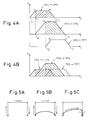
- Figs. 4A and 4B are time charts showing a content of a path motion plan in which a high smoothing ratio is designated for positions TP5 and TP6 in operation commands for movement along the path shown in Fig. 3, with the abscissa representing time t and the ordinate representing speed V.
- TP4, TP5, TP6 and TP7 designate teaching points for a tool point a position of which is predetermined with respect of the hand 6 of the robot, and an operation type is assumed to be designated such that the robot hand 6 moves linearly in the section from TP4 to TP5, the section from TP5 to TP6 and the section from TP6 to TP7.
- the position TP5 is only a transit point where the motion is changed from vertically upward movement to horizontal movement
- the position TP6 only a transit point where the motion is changed from horizontal movement to vertically downward movement, it is advantageous to designate a high smoothing ratio for the positions TP5 and TP6 in order to reduce the cycle time.
- the hand 6 follows a trajectory in which it temporarily deviates from the taught straight path from a point before the position TP5 to a point after the position TP6 and then moves toward a position TP7.
- a path motion plan is prepared so that a motion MNOP for linear movement along the teaching path from TP5 to TP6 is started at the same time the accelerating operation is completed (point J) in a motion IJKL for linear movement along the teaching path from TP4 to TP5 and so that a motion QRST for linear movement along the teaching path from TP6 to TP7 is started at the same time that completion of the accelerating operation is completed (point N) in a motion MNOP for linear movement along the teaching path from TP5 to TP6, as shown in Fig. 4A.
- Japanese Patent No. 3537229 proposes a method of ensuring that a hand moves along the teaching path in a path-assurance section designated near the terminal point of the movement path.
- the movement path deviates from the straight teaching path connecting TP1 and TP2 near the position TP1 and, therefore, the workpiece may not be pulled out smoothly.
- the hand 6 follows a curved path as indicated by reference numeral 8 in Fig. 3 and, over the whole range of the path from TP5 to TP6, the hand 6 does not reach the taught height. As a result, the hand 6 may interfere with an obstacle during horizontal movement.
- Japanese Patent No. 3537229 assures only the path for the approaching motion but not the path for the leaving motion. Therefore, the motion of pulling out the workpiece may cause a similar problem.
- measures have been taken such as (4) decreasing the command speed for the path sections from TP4 to TP5 and the command speed for the path section from TP6 to TP7, (5) designating a low smoothing ratio for the positions TP5 and TP6, or (6) increasing the distance of the positions TP5 and TP6 from the positions TP4 and TP7, respectively.
- an object of the present invention is to reduce the work load for adjusting the contents of the teaching by trial and error to obtain the desired motion path and to avoid the unnecessary increase of the cycle time due to the adjustment process based on trial and error, in order to obviate the problem of the prior art described above.
- a robot movement control method in which a robot is smoothly transferred from movement in a preceding path section to movement in a succeeding path section without an abrupt direction change by starting a motion for moving the robot along a teaching path for the succeeding path section before completion of a motion for moving the robot along a teaching path for the preceding path section so as to carry out the motion for movement along the teaching path in the preceding path section and the motion for movement along the teaching path in the succeeding path section with an overlap
- the method comprising the steps of: determining a motion for moving the robot along a teaching path from a designated starting point to a designated terminal point with respect to each of two continuous path sections including a preceding path section and a succeeding path section; designating a path-assurance section from the designated starting point to a designated route point on the teaching path for the preceding path section; preparing a path motion plan so that, after the robot is moved along the teaching path for the preceding path section in the path-assurance section and reaches the route point, the
- a robot movement control method in which a robot is smoothly transferred from movement in a preceding path section to movement in a succeeding path section without an abrupt direction change by starting a motion for moving the robot along a teaching path for the succeeding path section before completion of a motion for moving the robot along a teaching path for the preceding path section so as to carry out the motion for movement along the teaching path in the preceding path section and the motion for movement along the teaching path in the succeeding path section with an overlap, the method comprising the steps of: determining a motion for moving the robot along the teaching path from a designated starting point to a designated terminal point with respect to each of three continuous path sections including a first path section, a second path section following the first path section and a third path section following the second path section; designating a path-assurance section from a first intermediate point to a second intermediate point on the teaching path for the second path section; preparing a path motion plan so that the motion for moving the robot along the teaching path for the first path section is completed
- the path-assurance section can be designated in the terms of (1) a spatial length of the path-assurance section, (2) a ratio of the path-assurance section to the teaching path for the path section including the path-assurance section, or (3) the time required for the robot to move through the path-assurance section.
- the present invention is applicable especially effectively to a continuous picking operation. Further, the motion for movement in the path section preceding to the path section including the path-assurance section is completed before the movement in the path-assurance section, while the motion for movement in the path section following the path section including the path-assurance section is not started before completion of movement in the path-assurance section. Therefore, the robot can move along the teaching path for the path section including the path-assurance section without being affected by the motion for the preceding or succeeding path section.
- the effect of the motion for the preceding or succeeding path section can be eliminated in the section from the starting point to a route point in the desired movement section or the section near an intermediate point and, by designating a section desired to coincident with the teaching path in advance in the program, etc., as a path-assurance section, the job load for adjusting the contents of the teaching based on trial and error in the prior art can be reduced while avoiding the unnecessary increase of the cycle time.
- FIG. 10 is a block diagram showing a robot control unit for use in carrying out the method of the present invention.
- a robot control unit 20 includes a central processing unit (hereinafter referred to as the CPU) 21.
- the CPU 21 is connected, through a bus 29, with a memory 22 in the form of a read only memory (ROM), a memory 23 in the form of a random access memory (RAM), a nonvolatile memory 24, an input/output unit 25 for external devices, an interface 26 for a teaching operation panel 49, and a robot axis control portion 27.
- ROM read only memory
- RAM random access memory
- nonvolatile memory an input/output unit 25 for external devices
- an interface 26 for a teaching operation panel 49 and a robot axis control portion 27.
- the ROM 22 stores a program for controlling the whole system including the robot control unit 20.
- the RAM 23 is used to temporarily store data for the processing executed by the CPU 21.
- the nonvolatile memory 24 stores robot operation program data including the operation commands described later and various set values related to the operation of the individual parts of the system.
- the robot control portion 27 controls the operation of the individual axes of a robot mechanical part 30 through a servo circuit 28.
- the configuration and function of the above robot control unit are basically identical with those of the ordinary robot control unit.
- the characteristic feature of the present invention is exhibited when the operation program including the following operation commands is stored in the nonvolatile memory 24 and the playback operation is performed in accordance with the stored operation program.
- Fig. 6 extracts the movement path (TP1 ⁇ TP2 ⁇ TP3) in the case shown in Fig. 1, and shows the movement path including a path-assurance section in which the coincidence between the path of the hand for leaving the position TP1 and the teaching path is assured, with the robot arm, etc. omitted.
- a path-assurance section in which the coincidence between the path of the hand for leaving the position TP1 and the teaching path is assured, with the robot arm, etc. omitted.
- citing three examples of the operation command statement prepared so as to assure the path for movement from the position TP1 in the movement path, the process in the playback operation and the realized path for the robot hand path will be described.
- the path-assurance sections are designated in terms of (1) an absolute value of distance, (2) movement time, and (3) achievement ratio of movement along the teaching path, respectively.
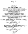
- the operation command 1 is read at step S1.
- a path motion plan for linearly moving the robot hand at the command speed of 2000 mm/sec to position it at the position TP1 is prepared.
- interpolation points are prepared by the interpolation function, and the prepared interpolation points are transferred to the servo circuit 28 for every processing cycle, thereby moving the robot hand to the position TP1 (step S2).
- step S3 the operation command 2 is read.
- a path motion plan for moving from the position TP1 to the position TP2 is determined, an interpolation process is executed based on the determined path motion plan (ABCD), and the preparation of interpolation points for individual axes and the transfer of the prepared interpolation points to the servo circuit 28 are started (step S4).
- the robot hand completes the acceleration at the point B, and the position on the path corresponding to the point B is given as P1.
- the position P1 is assumed to be located between the position TP1 and the position TP2, and the distance between TP1 and P1 corresponds to the area of the portion surrounded by the points ABB' in Fig. 7.
- the operation command 2 designates the path-assurance section of 100 mm from position TP1 and, therefore, a point U (point V) is calculated such that the area of the portion surrounded by the points ABUV in the time chart of Fig. 7 is 100 mm (step S5).
- the operation command 3 is read (step S6) and a path motion plan (EFGH) for the path from the position TP2 to the position TP3 is prepared in accordance with the ordinary method.
- the path motion plan is determined assuming that the point E and the point U (V) coincide with each other (step S7).
- an interpolation process is executed based on the determined path motion plan (EFGH), and the preparation of interpolation points for individual axes and the transfer of the prepared interpolation points to the servo circuit 28 are started (steps S8 and S9). Then, the movement path of the robot hand starts to deviate from the straight teaching path extending from TP1 to TP2, and the robot hand moves along a curved path indicated by numeral 9.
- EFGH determined path motion plan
- step S10 When a position on the path where the robot hand starts to deviate from the teaching path is given as P1, the position P2 is assumed to be located 100 mm distant from the position TP1 on the extension of the straight line connecting the positions TP1 and the position P1. Thereafter, when the robot hand completes the motion for moving along the path from the position TP2 to the position TP3 and reaches the terminal point TP3 (step S10), the process is completed. In this way, the movement of the robot hand is achieved to realize the path assurance designated by the operation command 2 in the first example of the operation command statement.
- the operation command 1 is read at step T1.
- a path motion plan for linearly moving the robot hand at the command speed of 2000 mm/sec to position it at the position TP1 is prepared.
- interpolation points are prepared by the interpolation function, and the prepared interpolation points are transferred to the servo circuit 28 for every processing cycle, thereby moving the robot hand to the position TP1 (step T2).
- the operation command 2 is read.
- a path motion plan for moving from the position TP1 to the position TP2 is determined, the interpolation process is executed based on the determined path motion plan (ABCD), and the preparation of interpolation points for individual axes and the transfer of the prepared interpolation points to the servo circuit 28 are started (step T4).
- the robot hand completes the acceleration at the point B, and the position on the path corresponding to the point B is given as P1, as in the first example of the operation command statement.
- the position P1 is assumed to be located between the position TP1 and the position TP2, and the distance between TP1 and P1 corresponds to the area of the portion surrounded by the points ABB' in Fig. 7.
- the operation command 2 designates the path-assurance section of 100 msec from the position TP1 and, therefore, a point V is calculated such that the time represented by the length between A and V in the time chart of Fig. 7 is 100 msec (step T5).
- the operation command 3 is read (step T6) and a path motion plan (EFGH) for the path from the position TP2 to the position TP3 is prepared in accordance with the ordinary method.
- the path motion plan is determined assuming that the point E and the point V coincide with each other (step T7).
- an interpolation process is executed based on the determined path motion plan (EFGH), and the preparation of interpolation points for individual axes and the transfer of the prepared interpolation points to the servo circuit 28 are started (steps T8 and T9). Then, the movement path of the robot hand starts to deviate from the straight teaching path extending from TP1 to TP2, and the robot hand moves along a curved path indicated by numeral 9.
- EFGH determined path motion plan
- the position P2 is assumed to be located on the extension of the straight line connecting the position TP1 and the position P1, and the distance from the position TP1 to the position P2 corresponds to the area of the portion surrounded by the points ABUV in Fig. 7.
- the robot hand completes the motion for moving along the path from the position TP2 to the position TP3 and reaches the terminal point TP3 (step T10), the process is completed. In this way, the movement of the robot hand is achieved to realize the path assurance designated by the operation command 2 in the second example of the operation command statement.
- the operation command 1 is read at step U1.
- a path motion plan for linearly moving the robot hand at the command speed of 2000 mm/sec to position it at the position TP1 is prepared.
- interpolation points are prepared by the interpolation function, and the prepared interpolation points are transferred to the servo circuit 28 for every processing cycle, thereby moving the robot hand to the position TP1 (step U2).
- the operation command 2 is read.
- a path motion plan for moving from the position TP1 to the position TP2 is determined, the interpolation process is executed based on the determined path motion plan (ABCD), and the preparation of interpolation points for individual axes and the transfer of the prepared interpolation points to the servo circuit 28 are started (step U4).
- the robot hand completes the acceleration at time point B, and the position on the path corresponding to the point B is given as P1, as in the first example of the operation command statement.
- the position P1 is assumed to be located between the position TP1 and the position TP2, and the distance between TP1 and P1 corresponds to the area of the portion surrounded by the points ABB' in Fig. 7.
- the operation command 2 designates the path-assurance section covering 30 % of the distance from the position TP1 to the position TP2 and, therefore, a point U is calculated such that the area of the portion surrounded by the points ABUV in the time chart of Fig. 7 corresponds to 30 % of the area of the portion surrounded by the points ABCD (step U5).
- the operation command 3 is read (step U6) and a path motion plan (EFGH) for the path from the position TP2 to the position TP3 is prepared in accordance with the ordinary method. In the process, the path motion plan is determined assuming that the point E and the point V coincide with each other (step U7).
- the position P2 is assumed to be located on the extension of the straight line connecting the position TP1 and the position P1, and the distance from the position TP1 to the position P2 corresponds to the area of the portion surrounded by the points ABUV in Fig. 7.
- the robot hand completes the motion for moving along the path from the position TP2 to the position TP3 and reaches the terminal point TP3 (step U10), the process is completed. In this way, the movement of the robot hand is achieved to realize the path assurance designated by the operation command 2 in the third example of the operation command statement.
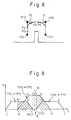
- Fig. 8 extracts the movement path (TP4 ⁇ TF5 ⁇ TF6 ⁇ TP7) in the case shown in Fig. 3, and shows the movement path including a path-assurance section in which the coincidence between the path for approaching to the position TP6 and the teaching path is assured, with the robot arm, etc. omitted.
- citing three examples of the operation command statement prepared so as to assure the path for an intermediate point in the movement path from TP5 to TP6, the process in the playback operation and the realized path for the robot hand will be described.
- the path-assurance sections are designated in terms of (1) an absolute value of distance, (2) movement time, and (3) achievement ratio of movement along the teaching path, respectively.
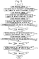
- the operation command 1 is read at step VI.
- a path motion plan for linearly moving the robot hand at the command speed of 2000 mm/sec to position it at the position TP4 is prepared.
- interpolation points are prepared by the interpolation function, and the prepared interpolation points are transferred to the servo circuit 28 for every processing cycle, thereby moving the robot hand to the position TP4 (step V2) .
- the operation command 2 is read. Further, a path motion plan for linearly moving the hand robot to the position TP5 is prepared in accordance with the ordinary method and transferred to the servo circuit 28 for every processing cycle, thereby starting the movement toward position TP5 (step V4).
- the robot hand completes the acceleration and can start the operation in accordance with the next operation command 3 at time point J.
- the position on the path corresponding to this point J is given as P3.
- the position P3 is assumed to be located before position TP5, and the distance between P3 and TP5 corresponds to the area of the portion surrounded by the points JJ'KL in Fig. 4A.
- the next operation command 3 is read (step V5), the process for preparing a path motion plan is started, and the time constant of acceleration/deceleration (inclination of the straight lines MN and OP) is calculated (step V6).
- the operation command 3 designates the path-assurance section as an intermediate range of 10 mm between the position TP5 and the position TP6 (the range of 5 mm before and after the intermediate point) and, therefore, a point M is calculated such that the area (representing the distance) of the portion surrounded by the points WX ⁇ in the time chart of Fig. 9 is 5 mm to thereby determine the path motion plan from TP5 to TP6 (step V7).
- the points ⁇ and ⁇ represent an intermediate point between the point N and the point O and an intermediate point between the point M and the point P, respectively, on the path MNOP shown in Fig. 9.
- the point M is calculated using the values of the command speed and the time constant.
- a point Y (point Z) is calculated such that the area (representing the distance) of the portion surrounded by the points ⁇ YZ is 5 mm.
- the area (representing the distance) of the portion surrounded by the points WXYZ is 10 mm and the designated path-assurance section is obtained.
- the interpolation process is executed based on the determined path motion plan (MNOP), and the preparation of interpolation points for individual axes and the transfer of the prepared interpolation points to the servo circuit 28 are started (steps V8 and V9).
- MNOP determined path motion plan
- the movement path of the robot hand starts to deviate from the straight teaching path extending from TP4 to TP5, and the robot hand moves along a curved path indicated by numeral 10 in Fig. 8.
- P4 a position on the path where the robot hand starts to deviate from the teaching path
- the position P4 is assumed to be located between the position P3 and the position TP5
- the distance between P4 and TP5 corresponds to the area of the portion surrounded by the points MM'KL in Fig. 9.
- the time point indicated by the point L in the time chart of Fig. 9 is reached, the motion for moving along the path from TP4 to TP5 is completed.
- the position of the robot hand (the point P5 in Fig.
- the robot hand moves linearly from the point P5 along the straight teaching path connecting TP5 and TP6.
- the operation command 4 is read (step V10) and a path motion plan (QRST) from the position TP6 to the position TP7 is prepared in accordance with the ordinary method.
- the path motion plan is determined assuming that the point Q and the point Y (point 2) coincide with each other (step V11).
- an interpolation process is executed based on the determined path motion plan (QRST), and the preparation of interpolation points for individual axes and the transfer of the prepared interpolation points to the servo circuit 28 are started (steps V12 and V13). Then, the movement path of the robot hand starts to deviate from the straight teaching path extending from TP5 to TP6, and the robot hand moves along a curved path indicated by numeral 11.
- the position P6 is assumed to be located 10 mm distant from the position P5 between the position P5 and the position TP6.
- step V14 the process is completed.
- the movement of the robot hand is achieved to realize the path assurance designated by the operation command 3 in the fourth example of the operation command statement.
- the operation command 1 is read at step W1.
- a path motion plan for linearly moving the robot hand at the command speed of 2000 mm/sec to position it at the position TP4 is prepared.
- interpolation points are prepared by the interpolation function, and the prepared interpolation points are transferred to the servo circuit 28 for every processing cycle, thereby moving the robot hand to the position TP4 (step W2).
- the operation command 2 is read. Further, in accordance with the ordinary method, a path motion plan for linearly moving the robot hand to the position TP5 is prepared. Based on the prepared path motion plan, interpolation points are prepared by the interpolation function and transferred to the servo circuit 28 for every processing cycle, thereby starting the movement toward the position TP5 (step W4).
- the robot hand completes the acceleration and can start the operation in accordance with the next operation command 3 at time point J.
- the position on the path corresponding to this point J is given as P3, as in the fourth example of the operation command statement.
- the position P3 is assumed to be located before position TP5, and the distance between P3 and TP5 corresponds to the area of the portion surrounded by the points JJ'KL in Fig. 4A.
- the next operation command 3 is read (step W5), the process for preparing a path motion plan is started, and the time constant of acceleration/deceleration (inclination of the straight lines MN and OP) is calculated (step W6).
- the operation command 3 designates the path-assurance section as an intermediate range of 10 msec between the position TP5 and the position TP6 (the range of 5 msec before and after the intermediate point) and, therefore, a point M is calculated such that the time represented by W ⁇ in the time chart of Fig. 9 is 5 msec to thereby determine the path motion plan from TP5 to TP6 (step W7).
- the points ⁇ and ⁇ represent an intermediate point between the point N and the point O and an intermediate point between the point M and the point P, respectively, on the path MNOP shown in Fig. 9.
- the point M is calculated using the values of the command speed and the time constant.
- a point Y (point Z) is calculated such that the time represented by ⁇ Z is 5 msec.
- the time represented by WZ is 10 msec and the designated path-assurance section is obtained.
- the movement path of the robot hand starts to deviate from the straight teaching path extending from TP4 to TP5, and the robot hand moves along a curved path indicated by numeral 10 in Fig. 8.
- P4 a position on the path where the robot hand starts to deviate from the teaching path
- the position P4 is assumed to be located between the position P3 and the position TP5
- the distance between P4 and TP5 corresponds to the area of the portion surrounded by the points MM'KL in Fig. 9.
- the time point indicated by the point L in the time chart of Fig. 9 is reached, the motion for moving along the path from TP4 to TP5 is completed.
- the position of the robot hand (the point P5 in Fig.
- the robot hand moves linearly from the point P5 along the straight teaching path connecting TP5 and TP6.
- the operation command 4 is read (step W10) and a path motion plan (QRST) from the position TP6 to the position TP7 is prepared in accordance with the ordinary method.
- the path motion plan is determined assuming that the point Q and the point Y (point Z) coincide with each other (step W11).
- an interpolation process is executed based on the determined path motion plan (QRST), and the preparation of interpolation points for individual axes and the transfer of the prepared interpolation points to the servo circuit 28 are started (steps W12 and W13). Then, the movement path of the robot hand starts to deviate from the straight teaching path extending from TP5 to TP6, and the robot hand moves along a curved path indicated by numeral 11.
- the position P6 is assumed to be located between the position P5 and the position TP6, and the distance between P5 and P6 corresponds to the area of the portion surrounded by the points WXYZ. Thereafter, when the robot hand completes the motion for moving along the path from the position TP6 to the position TP7 and reaches the terminal point TP7 (step W14), the process is completed. In this way, the movement of the robot hand is achieved to realize the path assurance designated by the motion command 3 in the fifth example of the operation command statement.
- the operation command 1 is read at step X1.
- a path motion plan for linear moving the robot hand at the command speed of 2000 mm/sec to position it at the position TP4 is prepared.
- interpolation points are prepared by the interpolation function, and the prepared interpolation points are transferred to the servo circuit 28 for every processing cycle, thereby moving the robot hand to the position TP4 (step X2).
- the operation command 2 is read. Further, in accordance with the ordinary method, a path motion plan for linearly moving the robot hand to the position TP5 is prepared. Based on the prepared path motion plan, interpolation points are prepared by the interpolation function and transferred to the servo circuit 28 for every processing cycle, thereby starting the movement toward the position TP5 (step X4). The robot hand completes the acceleration and can start the operation in accordance with the next operation command 3 at time point J. The position on the path corresponding to this point J is given as P3, as in the fourth example of the operation command statement.
- the position P3 is assumed to be located before the position TP5, and the distance between P3 and TP5 corresponds to the area of the portion surrounded by the points JJ'KL in Fig. 4A.
- the next operation command 3 is read (step X5), the process for preparing a path motion plan is started, and the time constant of acceleration/deceleration (inclination of the straight lines MN and OP) is calculated (step X6).
- the operation command 3 designates the path-assurance section as an intermediate range of 10% of the distance between the position TP5 and the position TP6 (the range of 5% of the distance between the position TP5 and the position TP6 before and after the intermediate point) and, therefore, a point M is calculated such that the area of the portion surrounded by the points WX ⁇ in the time chart of Fig. 9 is 5% of the area of the portion surrounded by the points MNOP to thereby determine the path motion plan from TP5 to TP6 (step X7).
- the points ⁇ and ⁇ represent an intermediate point between the point N and the point O and an intermediate point between the point M and the point P, respectively, on the path MNOP shown in Fig. 9.
- the point M is calculated using the values of the command speed and the time constant.
- a point Y (point Z) is calculated such that the area of the portion surrounded by the points ⁇ YZ is 5% of the area of the portion surrounded by the points MNOP.
- the area of the portion surrounded by the points WXYZ is 10% of the area of the portion surrounded by the points MNOP and the designated path-assurance section is obtained.
- the interpolation process is executed based on the determined path motion plan (MNOP), and the preparation of interpolation points for individual axes and the transfer of the prepared interpolation points to the servo circuit 28 are started (steps X8 and X9).
- MNOP determined path motion plan
- the movement path of the robot hand starts to deviate from the straight teaching path extending from TP4 to TP5, and the robot hand moves along a curved path indicated by numeral 10 in Fig. 8.
- P4 a position on the path where the robot hand starts to deviate from the teaching path
- the position P4 is assumed to be located between the position P3 and the position TP5
- the distance between P4 and TP5 corresponds to the area of the portion surrounded by the points MM'KL in Fig. 9.
- the time point indicated by point L in the time chart of Fig. 9 is reached, the motion for moving along the path from TP4 to TP5 is completed.
- the position of the robot hand (the point P5 in Fig.
- the robot hand moves linearly from point P5 along the straight teaching path connecting TP5 and TP6.
- the operation command 4 is read (step X10) and a path motion plan (QRST) from the position TP6 to the position TP7 is prepared in accordance with the ordinary method.
- the path motion plan is determined assuming that the point Q and the point Y (point Z) coincide with each other (step X11).
- an interpolation process is executed based on the determined path motion plan (QRST), and the preparation of interpolation points for individual axes and the transfer of the prepared interpolation points to the servo circuit 28 are started (steps X12 and X13). Then, the movement path of the robot hand starts to deviate from the straight teaching path extending from TP5 to TP6, and the robot hand moves along a curved path indicated by numeral 11.
Landscapes
- Engineering & Computer Science (AREA)
- Robotics (AREA)
- Mechanical Engineering (AREA)
- Manipulator (AREA)
- Numerical Control (AREA)
Applications Claiming Priority (1)
| Application Number | Priority Date | Filing Date | Title |
|---|---|---|---|
| JP2004283777A JP2006099347A (ja) | 2004-09-29 | 2004-09-29 | ロボット移動制御方法 |
Publications (1)
| Publication Number | Publication Date |
|---|---|
| EP1642691A2 true EP1642691A2 (de) | 2006-04-05 |
Family
ID=35462129
Family Applications (1)
| Application Number | Title | Priority Date | Filing Date |
|---|---|---|---|
| EP05021159A Withdrawn EP1642691A2 (de) | 2004-09-29 | 2005-09-28 | Verfahren zur Roboterbewegungssteuerung |
Country Status (4)
| Country | Link |
|---|---|
| US (1) | US20060184278A1 (de) |
| EP (1) | EP1642691A2 (de) |
| JP (1) | JP2006099347A (de) |
| CN (1) | CN1754664A (de) |
Cited By (2)
| Publication number | Priority date | Publication date | Assignee | Title |
|---|---|---|---|---|
| CN105690395A (zh) * | 2016-04-23 | 2016-06-22 | 韩少卿 | 工业机器人及其控制方法 |
| CN105835058A (zh) * | 2016-04-23 | 2016-08-10 | 韩少卿 | 一种程序生成系统 |
Families Citing this family (11)
| Publication number | Priority date | Publication date | Assignee | Title |
|---|---|---|---|---|
| CN102681544A (zh) * | 2012-05-21 | 2012-09-19 | 航天科工深圳(集团)有限公司 | 一种迷宫管道机器人自主巡径算法及具有该算法的机器人 |
| US9221175B2 (en) * | 2013-03-28 | 2015-12-29 | Denso Wave Incorporated | Method of generating path of multiaxial robot and control apparatus for the multiaxial robot |
| JP6474955B2 (ja) * | 2013-11-29 | 2019-02-27 | 株式会社ダイヘン | マニピュレータの移動制御装置及び移動制御方法 |
| JP6684549B2 (ja) * | 2015-06-11 | 2020-04-22 | 株式会社Kmc | 工作機械の数値制御装置、工作機械、工作機械の制御方法及びプログラム |
| CN105082156B (zh) * | 2015-08-12 | 2017-04-12 | 珞石(北京)科技有限公司 | 一种基于速度最优控制的空间轨迹平滑方法 |
| US20210260761A1 (en) * | 2018-07-04 | 2021-08-26 | Abb Schweiz Ag | Method And Control System For Controlling An Industrial Actuator |
| JP2021130183A (ja) | 2020-02-21 | 2021-09-09 | ソニーグループ株式会社 | 情報処理装置及び情報処理方法、コンピュータプログラム、並びに移動ロボット |
| DE112021001607B4 (de) * | 2020-05-25 | 2026-01-22 | Fanuc Corporation | Offlinelehrvorrichtung und bewegungsprogrammerzeugungsverfahren |
| JP7015423B1 (ja) | 2020-08-28 | 2022-02-02 | ファナック株式会社 | 数値制御装置 |
| CN116056835A (zh) * | 2020-08-28 | 2023-05-02 | 发那科株式会社 | 数值控制装置 |
| CN112405538B (zh) * | 2020-11-11 | 2022-05-27 | 配天机器人技术有限公司 | 一种机器人轴空间平滑轨迹规划方法及规划装置 |
Family Cites Families (10)
| Publication number | Priority date | Publication date | Assignee | Title |
|---|---|---|---|---|
| US4815007A (en) * | 1984-12-20 | 1989-03-21 | Seiko Epson Corporation | Apparatus for controlling a robot |
| JP2735126B2 (ja) * | 1988-12-27 | 1998-04-02 | キヤノン株式会社 | ロボットの制御方法及びその制御装置 |
| JP3168682B2 (ja) * | 1992-04-27 | 2001-05-21 | ソニー株式会社 | 数値制御装置 |
| JP3537229B2 (ja) * | 1995-07-28 | 2004-06-14 | ファナック株式会社 | ロボットの制御方法 |
| JP4091124B2 (ja) * | 1996-11-26 | 2008-05-28 | ファナック株式会社 | 動作経路シミュレーション機能を有するロボット制御装置 |
| JP4203696B2 (ja) * | 1999-10-20 | 2009-01-07 | 株式会社安川電機 | 産業用機械の動作確認方法および装置 |
| US6922606B1 (en) * | 1999-11-19 | 2005-07-26 | Siemens Energy & Automation, Inc. | Apparatus and method for smooth cornering in a motion control system |
| JP3666341B2 (ja) * | 2000-02-04 | 2005-06-29 | 三菱電機株式会社 | ロボット制御方法 |
| JP4364634B2 (ja) * | 2001-07-13 | 2009-11-18 | ブルックス オートメーション インコーポレイテッド | 二次元3自由度ロボットアームの軌道プラニング及び移動制御戦略 |
| US7792604B2 (en) * | 2005-03-23 | 2010-09-07 | Hurco Companies, Inc. | Method of performing additive lookahead for adaptive cutting feedrate control |
-
2004
- 2004-09-29 JP JP2004283777A patent/JP2006099347A/ja active Pending
-
2005
- 2005-09-28 EP EP05021159A patent/EP1642691A2/de not_active Withdrawn
- 2005-09-29 US US11/237,923 patent/US20060184278A1/en not_active Abandoned
- 2005-09-29 CN CN200510107886.0A patent/CN1754664A/zh active Pending
Cited By (4)
| Publication number | Priority date | Publication date | Assignee | Title |
|---|---|---|---|---|
| CN105690395A (zh) * | 2016-04-23 | 2016-06-22 | 韩少卿 | 工业机器人及其控制方法 |
| CN105835058A (zh) * | 2016-04-23 | 2016-08-10 | 韩少卿 | 一种程序生成系统 |
| CN105690395B (zh) * | 2016-04-23 | 2017-09-19 | 宁波市智能制造产业研究院 | 工业机器人及其控制方法 |
| CN105835058B (zh) * | 2016-04-23 | 2017-10-27 | 福州环亚众志计算机有限公司 | 一种程序生成系统 |
Also Published As
| Publication number | Publication date |
|---|---|
| US20060184278A1 (en) | 2006-08-17 |
| JP2006099347A (ja) | 2006-04-13 |
| CN1754664A (zh) | 2006-04-05 |
Similar Documents
| Publication | Publication Date | Title |
|---|---|---|
| EP1642691A2 (de) | Verfahren zur Roboterbewegungssteuerung | |
| EP0785490B1 (de) | Verfahren zur robotersteuerung | |
| US5254923A (en) | Industrial robot synchronous control method and apparatus | |
| JP6351900B2 (ja) | ロボット制御装置 | |
| US20060069466A1 (en) | Method for controlling trajectory of robot | |
| US11945118B2 (en) | Method of planning works for robots and work planning device | |
| US6163124A (en) | Robot controller | |
| EP1798618A2 (de) | Vorrichtung und Verfahren zum automatischen Setzen von Intelocks zwischen Robotern | |
| CN110900597B (zh) | 一种竖直高度和弯角高度可设置的跳跃运动轨迹规划方法 | |
| US8560112B2 (en) | Numerical controller with function to correct movement path of machining program | |
| KR100798970B1 (ko) | 로봇 컨트롤러 및 로봇 제어방법 | |
| US20220339791A1 (en) | Robot operation for a moving workpiece | |
| JPH0825262A (ja) | ロボットの教示方法 | |
| EP0568416A2 (de) | Numerische Steuervorrichtung zur Berechnung eines kurzen Bahnverlaufs eines Roboters | |
| US9983568B2 (en) | Numerical controller | |
| US5276777A (en) | Locus correcting method for industrial robots | |
| JPS62100813A (ja) | コ−ナ点のオ−バライド方法 | |
| KR100338469B1 (ko) | 수치 제어 장치 및 그 이송 제어 처리 방법 | |
| US5347461A (en) | Tool travel path creating method | |
| JPH06122025A (ja) | プレスブレーキロボットシステムのワーク曲げ追従方法 | |
| EP0371142B1 (de) | Korrekturverfahren für geometrische stellen bei industriellen robotern | |
| JP2000347715A (ja) | 数値制御装置 | |
| JPS60242987A (ja) | 産業用ロボツト | |
| JPH03213285A (ja) | ロボットの制御方法 | |
| JPH09254064A (ja) | 産業用ロボットにおける教示点追加方法 |
Legal Events
| Date | Code | Title | Description |
|---|---|---|---|
| PUAI | Public reference made under article 153(3) epc to a published international application that has entered the european phase |
Free format text: ORIGINAL CODE: 0009012 |
|
| AK | Designated contracting states |
Kind code of ref document: A2 Designated state(s): AT BE BG CH CY CZ DE DK EE ES FI FR GB GR HU IE IS IT LI LT LU LV MC NL PL PT RO SE SI SK TR |
|
| AX | Request for extension of the european patent |
Extension state: AL BA HR MK YU |
|
| STAA | Information on the status of an ep patent application or granted ep patent |
Free format text: STATUS: THE APPLICATION HAS BEEN WITHDRAWN |
|
| 18W | Application withdrawn |
Effective date: 20100601 |