EP1640821A1 - Watch movement with a plurality of balances - Google Patents
Watch movement with a plurality of balances Download PDFInfo
- Publication number
- EP1640821A1 EP1640821A1 EP04022608A EP04022608A EP1640821A1 EP 1640821 A1 EP1640821 A1 EP 1640821A1 EP 04022608 A EP04022608 A EP 04022608A EP 04022608 A EP04022608 A EP 04022608A EP 1640821 A1 EP1640821 A1 EP 1640821A1
- Authority
- EP
- European Patent Office
- Prior art keywords
- rockers
- escapement
- movement according
- frame
- movement
- Prior art date
- Legal status (The legal status is an assumption and is not a legal conclusion. Google has not performed a legal analysis and makes no representation as to the accuracy of the status listed.)
- Granted
Links
- 230000033001 locomotion Effects 0.000 title claims abstract description 39
- 230000000712 assembly Effects 0.000 claims 1
- 238000000429 assembly Methods 0.000 claims 1
- 230000008878 coupling Effects 0.000 description 8
- 238000010168 coupling process Methods 0.000 description 8
- 238000005859 coupling reaction Methods 0.000 description 8
- 230000000694 effects Effects 0.000 description 2
- 230000007935 neutral effect Effects 0.000 description 2
- 238000004804 winding Methods 0.000 description 2
- 230000005540 biological transmission Effects 0.000 description 1
- 230000001808 coupling effect Effects 0.000 description 1
- 230000000994 depressogenic effect Effects 0.000 description 1
- 238000012423 maintenance Methods 0.000 description 1
- 238000004519 manufacturing process Methods 0.000 description 1
- 230000010355 oscillation Effects 0.000 description 1
- 230000000717 retained effect Effects 0.000 description 1
Images


Classifications
-
- G—PHYSICS
- G04—HOROLOGY
- G04B—MECHANICALLY-DRIVEN CLOCKS OR WATCHES; MECHANICAL PARTS OF CLOCKS OR WATCHES IN GENERAL; TIME PIECES USING THE POSITION OF THE SUN, MOON OR STARS
- G04B17/00—Mechanisms for stabilising frequency
-
- G—PHYSICS
- G04—HOROLOGY
- G04B—MECHANICALLY-DRIVEN CLOCKS OR WATCHES; MECHANICAL PARTS OF CLOCKS OR WATCHES IN GENERAL; TIME PIECES USING THE POSITION OF THE SUN, MOON OR STARS
- G04B17/00—Mechanisms for stabilising frequency
- G04B17/20—Compensation of mechanisms for stabilising frequency
- G04B17/28—Compensation of mechanisms for stabilising frequency for the effect of unbalance of the weights, e.g. tourbillon
- G04B17/285—Tourbillons or carrousels
Abstract
Description
La présente invention concerne les mouvements de montre munis de plusieurs balanciers et plus particulièrement du type dit à résonance. Dans ce genre de mouvement, deux balanciers oscillent exactement à la même fréquence, interagissant l'un avec l'autre. Une telle solution permet d'augmenter sensiblement le rendement du mouvement et sa précision.The present invention relates to watch movements provided with several rockers and more particularly of the so-called resonance type. In this kind of movement, two pendulums oscillate exactly at the same frequency, interacting with each other. Such a solution can significantly increase the performance of the movement and its accuracy.
De telles montres ont déjà été réalisées. Pour assurer une mise en résonance, il est généralement prévu de pouvoir régler la distance entre les deux balanciers. Si les balanciers oscillent en opposition de phase au voisinage l'un de l'autre, l'air qu'ils entraînent va dans la même direction de telle sorte que les frottements dans l'air sont réduits. On comprendra aisément que cette distance est très faible et pose des problèmes d'ajustement en cours de fabrication.Such watches have already been made. To ensure resonance, it is generally expected to be able to adjust the distance between the two pendulums. If the pendulums oscillate in opposition of phase to the neighborhood of each other, the air which they drag goes in the same direction so that the friction in the air is reduced. It will be readily understood that this distance is very low and poses adjustment problems during manufacture.
La présente invention a pour but de pallier cet inconvénient en rendant plus rigide et plus simple la structure du mouvement équipé de balanciers travaillant en résonance. De manière plus précise, le mouvement selon l'invention est muni d'un bâti, d'une source d'énergie, d'une pluralité de balanciers travaillant en résonance, d'au moins un échappement entretenant le mouvement de l'un des balanciers et de moyens de liaison cinématique reliant la source d'énergie à l'échappement. Il est caractérisé en ce qu'il comporte, en outre :
- une structure de résonance sensiblement équilibrée en référence à un axe et sur laquelle sont montés pivotants les balanciers et l'échappement, et
- un organe de liaison reliant la structure de résonance au bâti et orienté selon cet axe.
- a resonance structure substantially balanced with reference to an axis and on which the rockers and the escapement are pivotally mounted, and
- a connecting member connecting the resonance structure to the frame and oriented along this axis.
Il semble que le fait de monter les balanciers et l'échappement sur une structure de résonance sensiblement équilibrée et reliée au bâti par un organe de liaison isolant mécaniquement cette structure du bâti lui-même, fait que l'inertie des pièces assurant le couplage est considérablement plus faible que celle de l'ensemble du bâti. Le couplage étant ainsi assuré par cette structure dans de très bonnes conditions, les balanciers peuvent être plus éloignés les uns des autres tout en conservant l'effet souhaité. Il n'est donc plus nécessaire d'effectuer des réglages délicats pour obtenir le phénomène de battement.It seems that the fact of mounting the rockers and the escapement on a substantially balanced resonance structure and connected to the frame by a connecting member mechanically insulating this structure of the frame itself, makes the inertia of the parts ensuring the coupling is considerably lower than that of the entire building. The coupling is thus ensured by this structure in very good conditions, the rockers can be further apart from each other while maintaining the desired effect. It is not therefore no longer necessary to make delicate adjustments to get the beat phenomenon.
Le mouvement peut comporter un seul échappement entraînant un balancier qui joue le rôle d'excitateur, les autres balanciers étant entraînés par couplage. Il est également possible que le mouvement comporte autant d'échappements que de balanciers, chaque échappement assurant l'entraînement d'un balancier. Dans ce cas, tous les balanciers jouent à la fois le rôle d'excitateur et de résonateur.The movement may comprise a single escapement driving a balance which acts as an exciter, the other balances being driven by coupling. It is also possible that the movement has as many escapements as rockers, each escapement ensuring the drive of a pendulum. In this case, all the pendulums play both the role of exciter and resonator.
La pratique a montré que, si les moyens de liaison cinématique comportent un seul rouage reliant la source d'énergie aux échappements, en d'autres termes, si tous les mobiles d'échappement sont entraînés par une même roue, alors, l'élasticité de l'engrènement est suffisante pour permettre le démarrage et la mise en phase des balanciers. Il n'est donc pas nécessaire de prévoir un différentiel entre le rouage unique et les échappements.Practice has shown that, if the kinematic linkage means comprise a single gear train connecting the energy source to the exhausts, in other words, if all the escape wheels are driven by the same wheel, then the elasticity meshing is sufficient to allow the starting and phasing of the pendulums. It is therefore not necessary to provide a differential between the single gear and the exhausts.
De manière avantageuse, la structure de résonance comporte une planche de roue reliée cinématiquement aux moyens de liaison cinématique et porte au moins deux balanciers et au moins un échappement. L'organe de liaison comporte au moins un pivotement formé d'une première partie coopérant avec le bâti, et une seconde partie solidaire de la structure de résonance. Cet organe est agencé de manière à permettre un pivotement de la structure sur le bâti. De la sorte, la structure de résonance peut pivoter sur le bâti et former ainsi un tourbillon.Advantageously, the resonance structure comprises a wheel plate kinematically connected to the kinematic connection means and carries at least two rockers and at least one escapement. The connecting member comprises at least one pivot formed by a first part cooperating with the frame, and a second part integral with the resonance structure. This member is arranged to allow pivoting of the structure on the frame. In this way, the resonance structure can pivot on the frame and thus form a vortex.
Dans une première variante, les balanciers et l'échappement sont montés directement sur la structure, alors que le bâti porte une roue fixe destinée à coopérer avec l'échappement pour permettre son entraînement lorsque la structure tourne. De la sorte, la structure de résonance forme un tourbillon avec les balanciers. La liaison avec le bâti peut se faire au moyen de deux paliers disposés de part et d'autre de la structure et coopérant avec le bâti. Il est également possible de faire tourner la structure sur un roulement à billes et ainsi constituer un tourbillon volant.In a first variant, the rockers and the escapement are mounted directly on the structure, while the frame carries a fixed wheel intended to cooperate with the exhaust to allow its drive when the structure rotates. In this way, the resonance structure forms a vortex with the pendulums. The connection with the frame can be done by means of two bearings arranged on either side of the structure and cooperating with the frame. It is also possible to rotate the structure on a ball bearing and thus constitute a flying tourbillon.
Dans une autre variante, particulièrement intéressante, le mouvement selon l'invention comporte, en outre, des cages montées pivotantes sur la structure de résonance et servant chacune de support à un balancier et à un échappement, et des roues fixes montées rigidement sur la structure, chacune d'elle étant coaxiale à l'une des cages et coopérant avec l'échappement pour former ainsi un tourbillon satellite, avantageusement de type volant, disposé sur la structure tournante.In another variant, particularly advantageous, the movement according to the invention further comprises cages pivotally mounted on the resonance structure and each serving as a support for a rocker and an escapement, and fixed wheels rigidly mounted on the structure, each of them being coaxial with one of the cages and cooperating with the exhaust to thereby form a satellite vortex, preferably flying type, disposed on the rotating structure.
Afin de renforcer le couplage entre les balanciers, les balanciers sont avantageusement montés pivotant sur leur cage par l'une de leurs extrémités et sur la structure de résonance par l'autre extrémité.In order to reinforce the coupling between the rockers, the rockers are advantageously mounted pivoting on their cage by one of their ends and on the resonance structure by the other end.
L'expérience montre qu'il est possible d'avoir une résonance entre trois balanciers, deux étant en phase et un en opposition de phase. En d'autres termes, il est possible de réaliser des mouvements munis d'un nombre impair de balanciers, avantageusement trois, lesquels travaillent en résonance.Experience shows that it is possible to have a resonance between three pendulums, two being in phase and one in opposition of phase. In other words, it is possible to perform movements provided with an odd number of balances, advantageously three, which work in resonance.
L'invention sera mieux comprise à la lecture de la description qui va suivre, donnée à titre d'exemple et faite en référence au dessin dans lequel :
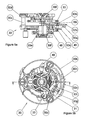
- les figures 1 et 2 représentent respectivement vu côté fond et côté cadran un mode particulier de réalisation d'un mouvement de montre selon l'invention,
- la figure 3 est une vue en coupe de la structure de résonance équipant ce mouvement,
- la figure 4 illustre, en perspective, les pièces participant à la cinématique du mouvement, et
- les figures 5a et 5b sont des vues respectivement en coupe et en plan d'une cage de tourbillon équipant le mouvement des figures 1 et 2.
- FIGS. 1 and 2 respectively show a bottom view and a dial side of a particular embodiment of a watch movement according to the invention,
- FIG. 3 is a sectional view of the resonance structure equipping this movement,
- FIG. 4 illustrates, in perspective, the parts participating in the motion kinematics, and
- FIGS. 5a and 5b are views in section and in plan respectively of a tourbillon cage equipping the movement of FIGS. 1 and 2.
Le mouvement de montre décrit ci-dessous comporte, de manière classique, un bâti formé d'une platine 10 et de ponts, plus particulièrement de deux ponts de barillets 12 et 14, d'un pont de finissage 16, et de deux ponts de tourbillons 18 et 20, respectivement visibles sur les figures 1 et 2 et disposés côté fond et côté cadran. De manière classique, les ponts sont fixés sur la platine 10 au moyen de vis non référencées.The watch movement described below comprises, in a conventional manner, a frame formed of a
Ce mouvement présente une forme particulière, constituée de deux demi-cercles reliés par une portion rectangulaire, la distance entre les centres des demi-cercles étant sensiblement égale au rayon des demi-cercles.This movement has a particular shape, consisting of two semicircles connected by a rectangular portion, the distance between the centers of the semicircles being substantially equal to the radius of the semicircles.
Ce mouvement comporte, en outre, notamment visibles sur les figures 1 et 4 :
- deux
barillets 22 et 24, assurant une fonction de source d'énergie, - un
renvoi 26 reliant cinématiquement les deux barillets, - un rouage de
finissage 28, - trois cages de
tourbillons 30 sur chacune desquelles sont disposés un échappement comprenant uneancre 31 et un mobile d'échappement 32, ainsi qu'un balancier 33, l'une de cescages 30 étant plus particulièrement visible sur les figures 5a et 5b, - un
plateau 34, mieux visible sur la figure 3, assurant une fonction de structure de résonance, monté pivotant entre lesponts 18 et 20 et sur lequel lescages 30 sont montées pivotantes, les axes de pivotement descages 30 formant entre eux un prisme de section triangulaire équilatérale, et - un mécanisme de remontoir et de mise à l'heure 36 comportant notamment une
tige 38 qui assure la liaison avec l'extérieur de la boîte dans laquelle est logé le mouvement.
- two
barrels - a
reference 26 kinematically connecting the two barrels, - a finishing
gear train 28, - three vortex stands 30 on each of which are disposed an escapement comprising an
anchor 31 and anescapement wheel 32, as well as arocker 33, one of thesecages 30 being more particularly visible in FIGS. 5a and 5b, - a
plate 34, better visible in FIG. 3, providing a resonance structure function, pivotally mounted between thebridges cages 30 are pivotally mounted, the pivot axes of thecages 30 forming between them a prism of equilateral triangular section, and - a winding and
setting mechanism 36 having in particular arod 38 which provides the connection with the outside of the box in which is housed the movement.
Dans ce mouvement, l'armage des ressorts de barillet se fait de manière classique, par une rotation de la tige 38 lorsqu'elle occupe sa position enfoncée, par l'intermédiaire de deux roues de rochets reliées entre elles par un renvoi. Les pièces assurant cette fonction ne présentant pas de caractère particulier, elles ne seront pas décrites en détail, ni référencées.In this movement, the winding of the barrel springs is done in a conventional manner, by a rotation of the
La figure 4 montre la cinématique du mouvement et notamment comment le barillet 22 transmet son énergie au barillet 24 par l'intermédiaire du renvoi 26. Le barillet 24 engrène avec le rouage de finissage 28, qui comporte un mobile de grande-moyenne décentrée 40, un mobile de petite moyenne 42, un mobile intermédiaire 43 et un mobile de secondes 44. Chacun de ces mobiles comprend un pignon identifié par la lettre a et une roue identifiée par la lettre b.FIG. 4 shows the kinematics of the movement and in particular how the
Le plateau 34, représenté en détail sur la figure 3, est de forme générale cylindrique et comporte une portion annulaire 34a munie d'une denture 34b à sa périphérie. Celle-ci est en prise avec la roue de secondes 44b, dans un rapport d'engrenages de 1 à 15, de telle sorte qu'il effectue un tour en quinze minutes. Le plateau comprend, en outre, un moyeu 34c et trois anneaux 34d disposés radialement à 120° les uns des autres et reliant la portion annulaire 34a au moyeu 34c.The
L'ouverture centrale que comporte chacun des anneaux 34d sert de logement à un roulement à billes 46 (figure 3) destiné à servir de pivotement à l'une des cages 30. Celle-ci est montée sur la bague intérieure du roulement 46 au moyen d'un clips facilement amovible et permettant de mettre en place et de retirer facilement les cages 30 du plateau 34.The central aperture of each of the
Chacun des anneaux 34d porte, disposée concentriquement, une roue 48 à denture intérieure, dont la fonction sera précisée ci-après, fixée rigidement au plateau 34 par des vis visibles sur la figure 1 et non référencées.Each of the
Le moyeu 34c est percé en son centre et sert de logement à un arbre 50 qui y est chassé, s'étendant de part et d'autre du plateau 34. L'arbre 50 est muni de pivots engagés dans des pierres fixées respectivement dans les ponts 18 et 20. L'arbre 50 forme ainsi un organe de liaison du plateau 34 au bâti, alors que ce dernier assure une fonction de structure de résonance.The
L'arbre 50 et le plateau 34 tournent, ensemble, autour d'un axe A perpendiculaire au plan du mouvement.The
Le plateau 34 et les cages 30 présentent une structure symétrique axiale, avec une périodicité de 120°, de telle sorte que l'ensemble est sensiblement équilibré par rapport à l'axe. En d'autres termes, les axes des cages 30, qui sont parallèles à l'axe A, forment ensemble un prisme à trois côtés, de section isocèle.The
Comme on peut le voir plus particulièrement sur les figures 5a et 5b, chacune des cages 30 comprend une planche 30a munie d'une denture 30b à sa périphérie, trois piliers 30c fixés sur un côté de la planche 30a et un pont de balancier 30d monté au moyen de vis sur les trois piliers 30c. Un moyeu 30e est solidaire de la planche 30a et s'engage sur le roulement à billes 46 pour assurer un pivotement volant de la cage 30 sur le plateau 34.As can be seen more particularly in Figures 5a and 5b, each of the
Le plateau 34 et le pont 30d sont munis, chacun, d'un palier 30f dans lequel oscille le balancier 33. La planche 30a porte deux pierres 30g et 30h et un pont d'échappement 30i (figure 4) également muni de pierres portant les mêmes références que celles disposées sur la planche 30a et servant de paliers à l'ancre 31 et au mobile d'échappement 32. Ce dernier comprend un pignon 32a engrenant avec la roue fixe 48 et une roue d'ancre 32b entraînant l'ancre 31, laquelle entretient le mouvement du balancier 33.The
Un manchon 52, muni d'une denture 52a à sa périphérie, est fixé sur le pont 18 et entoure l'arbre 50 (figure 3). La denture 52a est disposée de manière à ce qu'elle engrène avec la denture 30b. De la sorte, lorsque le plateau 34 tourne, les cages 30 se comportent comme les satellites d'un engrenage planétaire.A
Dans le mouvement ainsi décrit, l'énergie est fournie par les deux ressorts, logés dans les barillets 22 et 24, qui entraînent de manière classique le rouage de finissage 28. La roue de secondes 44 fait tourner le plateau 34. Ce dernier entraîne avec lui les cages 30, lesquelles sont en prises avec le manchon 52. Les cages 30 tendent donc à tourner sur elles-mêmes, sur le plateau 34. Elles sont retenues par leur roue d'échappement 32 et plus particulièrement par le pignon 32a qui est en prise avec la roue fixe 48. De la sorte, à chaque alternance du balancier, lors du passage au point mort, l'ancre 31 libère la roue d'échappement 32 qui donne alors une impulsion faisant basculer l'ancre 31 et transmettant de l'énergie au balancier 32.In the movement thus described, the energy is supplied by the two springs, housed in the
Il est évident qu'une telle solution ne peut fonctionner que dans la mesure où les trois balanciers oscillent exactement à la même fréquence, puisqu'ils doivent tourner à la même vitesse et passer ensemble au point mort, de manière à ce que le mouvement du plateau 34 permette la transmission d'énergie aux trois mobiles d'échappement 31. Cet ajustement se fait par résonance, dans la mesure, bien sûr, où les fréquences propres des balanciers sont très voisines. La résonance est obtenue grâce au fait que le plateau 34, avec sa structure annulaire et suspendue dans le bâti 14 par l'intermédiaire de l'arbre 50, permet un couplage optimal. On obtient ainsi un démarrage des balanciers et une mise en phase en un temps très bref, durant lequel les ébats et l'élasticité des engrenages suffisent pour assurer le fonctionnement durant les premières oscillations des balanciers. Le fait que les trois balanciers pivotent par l'une de leurs extrémités dans le plateau 34 renforce encore l'effet de couplage.It is obvious that such a solution can work only to the extent that the three pendulums oscillate exactly at the same frequency, since they must rotate at the same speed and pass together in neutral, so that the movement of the
Il va de soi que l'utilisation d'une telle structure peut tout aussi bien être utilisée sans tourbillon, tant au niveau du plateau que des cages. Il suffirait de disposer la roue de secondes 44 concentriquement au plateau 34, de telle sorte qu'elle engrène avec les trois pignons d'échappement 32a. Tout porte à penser que l'effet de résonance serait également obtenu.It goes without saying that the use of such a structure can just as easily be used without whirlwind, both at the plateau and the cages. It would be enough to have the wheel of
Si le plateau 34 portait au moins deux balanciers et deux échappements, chacun d'eux assurant l'entraînement d'un balancier, on se trouverait alors en présence d'un tourbillon simple à deux balanciers. Dans ce cas, les pignons des roues d'échappement coopéreraient avec une roue fixe concentrique à l'arbre 50, la planche 34 étant entraînée comme expliqué plus haut. En variante, seul l'un des balanciers pourrait être entraîné par un échappement, l'autre étant entraîné par couplage en résonance.If the
Afin de faciliter le démarrage, il est possible de remplacer le manchon 52 par un engrenage différentiel qui entraînerait les trois cages de manière autonome. Il serait également possible d'avoir trois barillets et trois rouages, chacun d'eux entraînant un balancier. Dans ce cas toutefois, et contrairement aux solutions connues, un réglage du couplage n'est pas nécessaire.In order to facilitate starting, it is possible to replace the
Il a été constaté que, de manière surprenante, même en disposant trois balanciers sur le plateau, il apparaît un phénomène de résonance.It has been found that, surprisingly, even with three pendulums on the plate, there appears a phenomenon of resonance.
Tant les cages que le plateau forment des tourbillons, les cages étant de type volant. Il est également possible d'avoir le plateau monté sur un roulement à billes pour former aussi un tourbillon volant, les cages pouvant alors être volantes ou non.Both the cages and the plate form swirls, the cages being of flying type. It is also possible to have the tray mounted on a ball bearing to also form a flying tourbillon, cages can then be flying or not.
Dans une variante qui n'a pas été représentée, il est également envisageable de disposer un ou deux balanciers à oscillation libre, c'est à dire sans moyens d'entretien, le troisième balancier étant entraîné par un échappement. Le troisième balancier assure alors la fonction de maître et les deux autres oscillent par couplage, en référence au troisième. Les deux balanciers seront avantageusement d'inertie plus faible que le troisième, de manière à ce que les amplitudes des trois balanciers soient sensiblement les mêmes.In a variant that has not been shown, it is also conceivable to have one or two freely oscillating rockers, that is to say without maintenance means, the third beam being driven by an escapement. The third balance then acts as master and the other two oscillate by coupling, with reference to the third. The two rockers will advantageously lower inertia than the third, so that the amplitudes of the three rockers are substantially the same.
On relèvera encore que, de façon avantageuse, la position relative des trois balanciers sera choisie de manière à ce que leurs points d'attache soient décalés de 120°. De la sorte, l'erreur de position est mieux moyennée dans les positions verticales.It will be noted again that, advantageously, the relative position of the three rockers will be chosen so that their attachment points are offset by 120 °. In this way, the position error is better averaged in the vertical positions.
Ainsi, grâce au fait que le mouvement selon l'invention comporte une structure de résonance sur laquelle sont montés les balanciers, et un organe de liaison reliant la structure au bâti et agencé de manière à ce que la structure soit isolée mécaniquement du bâti, les balanciers se mettent en résonance sans mesure particulière relative à la distance qui les sépare.Thus, thanks to the fact that the movement according to the invention comprises a resonance structure on which the rockers are mounted, and a connecting member connecting the structure to the frame and arranged so that the structure is mechanically isolated from the frame, the pendulums resonate without any particular measure of the distance between them.
Claims (10)
Priority Applications (8)
| Application Number | Priority Date | Filing Date | Title |
|---|---|---|---|
| AT04022608T ATE429667T1 (en) | 2004-09-22 | 2004-09-22 | CLOCK MOVEMENT WITH SEVERAL BALANCES |
| EP04022608A EP1640821B1 (en) | 2004-09-22 | 2004-09-22 | Watch movement with a plurality of balances |
| DE602004028972T DE602004028972D1 (en) | 2004-09-22 | 2004-09-22 | Tourbillon for movement and this movement containing |
| EP08001704A EP1918790B1 (en) | 2004-09-22 | 2004-09-22 | Tourbillon for watch movement and movement comprising the same |
| DE602004020766T DE602004020766D1 (en) | 2004-09-22 | 2004-09-22 | Clockwork with several riots |
| AT08001704T ATE479923T1 (en) | 2004-09-22 | 2004-09-22 | TOURBILLON FOR CLOCK MOVEMENT AND THE MOVEMENT THAT CONTAINS IT |
| PCT/IB2005/002778 WO2006032974A2 (en) | 2004-09-22 | 2005-09-20 | Watch movement provided with several balance wheels |
| HK06110456.0A HK1088669A1 (en) | 2004-09-22 | 2006-09-20 | Watch movement with a plurality of balances |
Applications Claiming Priority (1)
| Application Number | Priority Date | Filing Date | Title |
|---|---|---|---|
| EP04022608A EP1640821B1 (en) | 2004-09-22 | 2004-09-22 | Watch movement with a plurality of balances |
Related Child Applications (1)
| Application Number | Title | Priority Date | Filing Date |
|---|---|---|---|
| EP08001704A Division EP1918790B1 (en) | 2004-09-22 | 2004-09-22 | Tourbillon for watch movement and movement comprising the same |
Publications (2)
| Publication Number | Publication Date |
|---|---|
| EP1640821A1 true EP1640821A1 (en) | 2006-03-29 |
| EP1640821B1 EP1640821B1 (en) | 2009-04-22 |
Family
ID=34926666
Family Applications (2)
| Application Number | Title | Priority Date | Filing Date |
|---|---|---|---|
| EP04022608A Active EP1640821B1 (en) | 2004-09-22 | 2004-09-22 | Watch movement with a plurality of balances |
| EP08001704A Active EP1918790B1 (en) | 2004-09-22 | 2004-09-22 | Tourbillon for watch movement and movement comprising the same |
Family Applications After (1)
| Application Number | Title | Priority Date | Filing Date |
|---|---|---|---|
| EP08001704A Active EP1918790B1 (en) | 2004-09-22 | 2004-09-22 | Tourbillon for watch movement and movement comprising the same |
Country Status (5)
| Country | Link |
|---|---|
| EP (2) | EP1640821B1 (en) |
| AT (2) | ATE479923T1 (en) |
| DE (2) | DE602004020766D1 (en) |
| HK (1) | HK1088669A1 (en) |
| WO (1) | WO2006032974A2 (en) |
Cited By (7)
| Publication number | Priority date | Publication date | Assignee | Title |
|---|---|---|---|---|
| EP1903408A2 (en) * | 2006-09-25 | 2008-03-26 | Franck Müller Watchland SA | Tourbillon for a timepiece |
| CH702062A1 (en) * | 2009-10-26 | 2011-04-29 | Piguet & Co Horlogerie | Organ regulator comprising at least two balance wheels, a movement, and timepiece including such a body. |
| WO2011058157A1 (en) * | 2009-11-16 | 2011-05-19 | Complitime Sa | Timepiece movement |
| CN103439872A (en) * | 2013-09-06 | 2013-12-11 | 烟台持久钟表集团有限公司 | Tourbillon planet clock mechanism |
| WO2014180767A1 (en) * | 2013-05-07 | 2014-11-13 | Hublot Sa, Genève | Timepiece movement having a three-dimensional resonance regulator |
| WO2016139196A1 (en) | 2015-03-04 | 2016-09-09 | Hublot Sa, Genève | Time-keeping movement comprising a regulator with three-dimensional magnetic resonance |
| CH713109A1 (en) * | 2016-11-04 | 2018-05-15 | Concepto Holding Sa | Clockwork movement comprising at least two tourbillon mechanisms. |
Families Citing this family (3)
| Publication number | Priority date | Publication date | Assignee | Title |
|---|---|---|---|---|
| EP2450756B1 (en) * | 2010-11-04 | 2015-01-07 | Nivarox-FAR S.A. | Anti-tripping device for escapement mechanism |
| EP3015924B1 (en) | 2014-11-03 | 2017-08-09 | Antoine Preziuso Genève SA | Differential, in particular for timepieces |
| EP4194961A1 (en) * | 2021-12-07 | 2023-06-14 | H.K. Precision Technology Co. Ltd | Regulator assembly, for timepiece movement, comprising a cage to be rotatably mounted on a ball bearing |
Citations (2)
| Publication number | Priority date | Publication date | Assignee | Title |
|---|---|---|---|---|
| GB388258A (en) * | 1931-05-13 | 1933-02-23 | Marcel Vuilleumier | Improvements relating to horological movements |
| GB2375619A (en) * | 2001-05-14 | 2002-11-20 | Souza Paul Gerard D | Differential tourbillon escapement |
Family Cites Families (1)
| Publication number | Priority date | Publication date | Assignee | Title |
|---|---|---|---|---|
| JP4555336B2 (en) * | 2004-04-15 | 2010-09-29 | モントレー ブレゲ・エス アー | Wristwatch with two turbirons |
-
2004
- 2004-09-22 EP EP04022608A patent/EP1640821B1/en active Active
- 2004-09-22 DE DE602004020766T patent/DE602004020766D1/en active Active
- 2004-09-22 AT AT08001704T patent/ATE479923T1/en not_active IP Right Cessation
- 2004-09-22 AT AT04022608T patent/ATE429667T1/en not_active IP Right Cessation
- 2004-09-22 DE DE602004028972T patent/DE602004028972D1/en active Active
- 2004-09-22 EP EP08001704A patent/EP1918790B1/en active Active
-
2005
- 2005-09-20 WO PCT/IB2005/002778 patent/WO2006032974A2/en active Application Filing
-
2006
- 2006-09-20 HK HK06110456.0A patent/HK1088669A1/en unknown
Patent Citations (2)
| Publication number | Priority date | Publication date | Assignee | Title |
|---|---|---|---|---|
| GB388258A (en) * | 1931-05-13 | 1933-02-23 | Marcel Vuilleumier | Improvements relating to horological movements |
| GB2375619A (en) * | 2001-05-14 | 2002-11-20 | Souza Paul Gerard D | Differential tourbillon escapement |
Cited By (14)
| Publication number | Priority date | Publication date | Assignee | Title |
|---|---|---|---|---|
| EP1903408A3 (en) * | 2006-09-25 | 2011-05-25 | Franck Müller Watchland SA | Tourbillon for a timepiece |
| EP1903408A2 (en) * | 2006-09-25 | 2008-03-26 | Franck Müller Watchland SA | Tourbillon for a timepiece |
| US8668378B2 (en) | 2009-10-26 | 2014-03-11 | Societe Anonyme De La Manufacture D'horlogerie Audemars Piguet & Cie | Regulating organ comprising at least two balances |
| CH702062A1 (en) * | 2009-10-26 | 2011-04-29 | Piguet & Co Horlogerie | Organ regulator comprising at least two balance wheels, a movement, and timepiece including such a body. |
| WO2011058157A1 (en) * | 2009-11-16 | 2011-05-19 | Complitime Sa | Timepiece movement |
| CH702294A1 (en) * | 2009-11-16 | 2011-05-31 | Complitime Sa | Movement timepiece. |
| WO2014180767A1 (en) * | 2013-05-07 | 2014-11-13 | Hublot Sa, Genève | Timepiece movement having a three-dimensional resonance regulator |
| CH708038A1 (en) * | 2013-05-07 | 2014-11-14 | Hublot S A Genève | watch movement in three-dimensional resonant controller. |
| JP2016520833A (en) * | 2013-05-07 | 2016-07-14 | ウブロ ソシエテ アノニム, ジュネーブHublot S.A., Geneve | Watch movement with 3D resonant governor |
| CN103439872A (en) * | 2013-09-06 | 2013-12-11 | 烟台持久钟表集团有限公司 | Tourbillon planet clock mechanism |
| CN103439872B (en) * | 2013-09-06 | 2016-06-15 | 烟台持久钟表集团有限公司 | Top flywheel planet clockwork |
| WO2016139196A1 (en) | 2015-03-04 | 2016-09-09 | Hublot Sa, Genève | Time-keeping movement comprising a regulator with three-dimensional magnetic resonance |
| US10481556B2 (en) | 2015-03-04 | 2019-11-19 | Hublot Sa, Geneve | Time-keeping movement comprising a regulator with three-dimensional magnetic resonance |
| CH713109A1 (en) * | 2016-11-04 | 2018-05-15 | Concepto Holding Sa | Clockwork movement comprising at least two tourbillon mechanisms. |
Also Published As
| Publication number | Publication date |
|---|---|
| DE602004028972D1 (en) | 2010-10-14 |
| ATE479923T1 (en) | 2010-09-15 |
| WO2006032974A3 (en) | 2006-08-31 |
| DE602004020766D1 (en) | 2009-06-04 |
| WO2006032974A2 (en) | 2006-03-30 |
| ATE429667T1 (en) | 2009-05-15 |
| EP1918790B1 (en) | 2010-09-01 |
| EP1640821B1 (en) | 2009-04-22 |
| EP1918790A2 (en) | 2008-05-07 |
| EP1918790A3 (en) | 2009-01-28 |
| HK1088669A1 (en) | 2006-11-10 |
Similar Documents
| Publication | Publication Date | Title |
|---|---|---|
| WO2006032974A2 (en) | Watch movement provided with several balance wheels | |
| EP1738230B1 (en) | Watch comprising at least two tourbillons | |
| EP2115536B1 (en) | Watch movement | |
| EP1772783B1 (en) | Watch movement with constant-force device | |
| EP2246752B1 (en) | Tourbillon without the balance weight. | |
| CH687795B5 (en) | Piece mechanical timepiece provided with a tourbillon. | |
| EP1664941B8 (en) | Watch movement with an animation | |
| WO2012062659A1 (en) | Timepiece | |
| EP2802942B1 (en) | Timepiece having a plurality of balances | |
| EP4194962A1 (en) | Timepiece movement comprising an adjusting member provided with a means for variable adjustment of the inclination | |
| EP4194963A1 (en) | Timepiece movement comprising a member provided with a means for variable adjustment of the inclination | |
| EP4194958A1 (en) | Timepiece movement comprising a movable member provided with a means for variable adjustment of the inclination | |
| CH695797A5 (en) | Watch, has two tourbillons mounted on common rotating support, and connected by respective trains to differential gear that averages speed of carrier and output wheel in revolution speed of plate | |
| WO2018215284A1 (en) | Adjustment device for timepiece with isotropic harmonic oscillator having rotating masses and a common return force | |
| EP3772674A1 (en) | Mechanism for animation of an object for a piece of jewellery or costume jewellery | |
| EP3015924B1 (en) | Differential, in particular for timepieces | |
| CH713829A1 (en) | Control device for a timepiece with isotropic harmonic oscillator having rotating masses and a common return force. | |
| EP2189855B1 (en) | Tourbillon mechanism | |
| WO2021023710A1 (en) | Jewellery piece comprising a mechanism for animating an object | |
| CH720090A1 (en) | Regulator assembly for watch movement, watch movement and corresponding timepiece | |
| WO2023170161A1 (en) | Bridge for guiding a balance of a timepiece | |
| CH716486A2 (en) | Mechanism for animating an object for a piece of jewelry or jewelry. | |
| CH719233A2 (en) | Clock movement comprising a member provided with means for variable adjustment of the inclination. | |
| CH719232A2 (en) | Clockwork movement comprising a movable member provided with means for variable adjustment of the inclination. | |
| EP4239416A1 (en) | Clock movement with a mechanism for moving an oscillator |
Legal Events
| Date | Code | Title | Description |
|---|---|---|---|
| PUAI | Public reference made under article 153(3) epc to a published international application that has entered the european phase |
Free format text: ORIGINAL CODE: 0009012 |
|
| AK | Designated contracting states |
Kind code of ref document: A1 Designated state(s): AT BE BG CH CY CZ DE DK EE ES FI FR GB GR HU IE IT LI LU MC NL PL PT RO SE SI SK TR |
|
| AX | Request for extension of the european patent |
Extension state: AL HR LT LV MK |
|
| 17P | Request for examination filed |
Effective date: 20060823 |
|
| REG | Reference to a national code |
Ref country code: HK Ref legal event code: DE Ref document number: 1088669 Country of ref document: HK |
|
| AKX | Designation fees paid |
Designated state(s): AT BE BG CH CY CZ DE DK EE ES FI FR GB GR HU IE IT LI LU MC NL PL PT RO SE SI SK TR |
|
| GRAP | Despatch of communication of intention to grant a patent |
Free format text: ORIGINAL CODE: EPIDOSNIGR1 |
|
| GRAP | Despatch of communication of intention to grant a patent |
Free format text: ORIGINAL CODE: EPIDOSNIGR1 |
|
| GRAS | Grant fee paid |
Free format text: ORIGINAL CODE: EPIDOSNIGR3 |
|
| GRAA | (expected) grant |
Free format text: ORIGINAL CODE: 0009210 |
|
| AK | Designated contracting states |
Kind code of ref document: B1 Designated state(s): AT BE BG CH CY CZ DE DK EE ES FI FR GB GR HU IE IT LI LU MC NL PL PT RO SE SI SK TR |
|
| REG | Reference to a national code |
Ref country code: GB Ref legal event code: FG4D Free format text: NOT ENGLISH |
|
| REG | Reference to a national code |
Ref country code: CH Ref legal event code: EP |
|
| REG | Reference to a national code |
Ref country code: IE Ref legal event code: FG4D |
|
| REF | Corresponds to: |
Ref document number: 602004020766 Country of ref document: DE Date of ref document: 20090604 Kind code of ref document: P |
|
| REG | Reference to a national code |
Ref country code: CH Ref legal event code: NV Representative=s name: MICHELI & CIE SA |
|
| REG | Reference to a national code |
Ref country code: HK Ref legal event code: GR Ref document number: 1088669 Country of ref document: HK |
|
| NLV1 | Nl: lapsed or annulled due to failure to fulfill the requirements of art. 29p and 29m of the patents act | ||
| PG25 | Lapsed in a contracting state [announced via postgrant information from national office to epo] |
Ref country code: ES Free format text: LAPSE BECAUSE OF FAILURE TO SUBMIT A TRANSLATION OF THE DESCRIPTION OR TO PAY THE FEE WITHIN THE PRESCRIBED TIME-LIMIT Effective date: 20090802 Ref country code: AT Free format text: LAPSE BECAUSE OF FAILURE TO SUBMIT A TRANSLATION OF THE DESCRIPTION OR TO PAY THE FEE WITHIN THE PRESCRIBED TIME-LIMIT Effective date: 20090422 Ref country code: FI Free format text: LAPSE BECAUSE OF FAILURE TO SUBMIT A TRANSLATION OF THE DESCRIPTION OR TO PAY THE FEE WITHIN THE PRESCRIBED TIME-LIMIT Effective date: 20090422 Ref country code: PT Free format text: LAPSE BECAUSE OF FAILURE TO SUBMIT A TRANSLATION OF THE DESCRIPTION OR TO PAY THE FEE WITHIN THE PRESCRIBED TIME-LIMIT Effective date: 20090822 |
|
| PG25 | Lapsed in a contracting state [announced via postgrant information from national office to epo] |
Ref country code: SE Free format text: LAPSE BECAUSE OF FAILURE TO SUBMIT A TRANSLATION OF THE DESCRIPTION OR TO PAY THE FEE WITHIN THE PRESCRIBED TIME-LIMIT Effective date: 20090722 Ref country code: NL Free format text: LAPSE BECAUSE OF FAILURE TO SUBMIT A TRANSLATION OF THE DESCRIPTION OR TO PAY THE FEE WITHIN THE PRESCRIBED TIME-LIMIT Effective date: 20090422 Ref country code: SI Free format text: LAPSE BECAUSE OF FAILURE TO SUBMIT A TRANSLATION OF THE DESCRIPTION OR TO PAY THE FEE WITHIN THE PRESCRIBED TIME-LIMIT Effective date: 20090422 Ref country code: PL Free format text: LAPSE BECAUSE OF FAILURE TO SUBMIT A TRANSLATION OF THE DESCRIPTION OR TO PAY THE FEE WITHIN THE PRESCRIBED TIME-LIMIT Effective date: 20090422 |
|
| REG | Reference to a national code |
Ref country code: IE Ref legal event code: FD4D |
|
| PG25 | Lapsed in a contracting state [announced via postgrant information from national office to epo] |
Ref country code: EE Free format text: LAPSE BECAUSE OF FAILURE TO SUBMIT A TRANSLATION OF THE DESCRIPTION OR TO PAY THE FEE WITHIN THE PRESCRIBED TIME-LIMIT Effective date: 20090422 Ref country code: CZ Free format text: LAPSE BECAUSE OF FAILURE TO SUBMIT A TRANSLATION OF THE DESCRIPTION OR TO PAY THE FEE WITHIN THE PRESCRIBED TIME-LIMIT Effective date: 20090422 Ref country code: RO Free format text: LAPSE BECAUSE OF FAILURE TO SUBMIT A TRANSLATION OF THE DESCRIPTION OR TO PAY THE FEE WITHIN THE PRESCRIBED TIME-LIMIT Effective date: 20090422 Ref country code: IE Free format text: LAPSE BECAUSE OF FAILURE TO SUBMIT A TRANSLATION OF THE DESCRIPTION OR TO PAY THE FEE WITHIN THE PRESCRIBED TIME-LIMIT Effective date: 20090422 Ref country code: DK Free format text: LAPSE BECAUSE OF FAILURE TO SUBMIT A TRANSLATION OF THE DESCRIPTION OR TO PAY THE FEE WITHIN THE PRESCRIBED TIME-LIMIT Effective date: 20090422 |
|
| PG25 | Lapsed in a contracting state [announced via postgrant information from national office to epo] |
Ref country code: SK Free format text: LAPSE BECAUSE OF FAILURE TO SUBMIT A TRANSLATION OF THE DESCRIPTION OR TO PAY THE FEE WITHIN THE PRESCRIBED TIME-LIMIT Effective date: 20090422 |
|
| PLBE | No opposition filed within time limit |
Free format text: ORIGINAL CODE: 0009261 |
|
| STAA | Information on the status of an ep patent application or granted ep patent |
Free format text: STATUS: NO OPPOSITION FILED WITHIN TIME LIMIT |
|
| 26N | No opposition filed |
Effective date: 20100125 |
|
| BERE | Be: lapsed |
Owner name: ANTOINE PREZIUSO GENEVE SA Effective date: 20090930 |
|
| PG25 | Lapsed in a contracting state [announced via postgrant information from national office to epo] |
Ref country code: BG Free format text: LAPSE BECAUSE OF FAILURE TO SUBMIT A TRANSLATION OF THE DESCRIPTION OR TO PAY THE FEE WITHIN THE PRESCRIBED TIME-LIMIT Effective date: 20090722 |
|
| PG25 | Lapsed in a contracting state [announced via postgrant information from national office to epo] |
Ref country code: MC Free format text: LAPSE BECAUSE OF NON-PAYMENT OF DUE FEES Effective date: 20090930 |
|
| PG25 | Lapsed in a contracting state [announced via postgrant information from national office to epo] |
Ref country code: BE Free format text: LAPSE BECAUSE OF NON-PAYMENT OF DUE FEES Effective date: 20090930 |
|
| PG25 | Lapsed in a contracting state [announced via postgrant information from national office to epo] |
Ref country code: GR Free format text: LAPSE BECAUSE OF FAILURE TO SUBMIT A TRANSLATION OF THE DESCRIPTION OR TO PAY THE FEE WITHIN THE PRESCRIBED TIME-LIMIT Effective date: 20090723 |
|
| PG25 | Lapsed in a contracting state [announced via postgrant information from national office to epo] |
Ref country code: IT Free format text: LAPSE BECAUSE OF FAILURE TO SUBMIT A TRANSLATION OF THE DESCRIPTION OR TO PAY THE FEE WITHIN THE PRESCRIBED TIME-LIMIT Effective date: 20090422 |
|
| PG25 | Lapsed in a contracting state [announced via postgrant information from national office to epo] |
Ref country code: LU Free format text: LAPSE BECAUSE OF NON-PAYMENT OF DUE FEES Effective date: 20090922 |
|
| PG25 | Lapsed in a contracting state [announced via postgrant information from national office to epo] |
Ref country code: HU Free format text: LAPSE BECAUSE OF FAILURE TO SUBMIT A TRANSLATION OF THE DESCRIPTION OR TO PAY THE FEE WITHIN THE PRESCRIBED TIME-LIMIT Effective date: 20091023 |
|
| PG25 | Lapsed in a contracting state [announced via postgrant information from national office to epo] |
Ref country code: TR Free format text: LAPSE BECAUSE OF FAILURE TO SUBMIT A TRANSLATION OF THE DESCRIPTION OR TO PAY THE FEE WITHIN THE PRESCRIBED TIME-LIMIT Effective date: 20090422 |
|
| PG25 | Lapsed in a contracting state [announced via postgrant information from national office to epo] |
Ref country code: CY Free format text: LAPSE BECAUSE OF FAILURE TO SUBMIT A TRANSLATION OF THE DESCRIPTION OR TO PAY THE FEE WITHIN THE PRESCRIBED TIME-LIMIT Effective date: 20090422 |
|
| REG | Reference to a national code |
Ref country code: FR Ref legal event code: PLFP Year of fee payment: 13 |
|
| REG | Reference to a national code |
Ref country code: FR Ref legal event code: PLFP Year of fee payment: 14 |
|
| REG | Reference to a national code |
Ref country code: FR Ref legal event code: PLFP Year of fee payment: 15 |
|
| PGFP | Annual fee paid to national office [announced via postgrant information from national office to epo] |
Ref country code: GB Payment date: 20230920 Year of fee payment: 20 |
|
| PGFP | Annual fee paid to national office [announced via postgrant information from national office to epo] |
Ref country code: FR Payment date: 20230928 Year of fee payment: 20 Ref country code: DE Payment date: 20230920 Year of fee payment: 20 |
|
| PGFP | Annual fee paid to national office [announced via postgrant information from national office to epo] |
Ref country code: CH Payment date: 20231002 Year of fee payment: 20 |