EP1640145A1 - Entraînement direct et régulation pour presse à excentrique - Google Patents
Entraînement direct et régulation pour presse à excentrique Download PDFInfo
- Publication number
- EP1640145A1 EP1640145A1 EP04022983A EP04022983A EP1640145A1 EP 1640145 A1 EP1640145 A1 EP 1640145A1 EP 04022983 A EP04022983 A EP 04022983A EP 04022983 A EP04022983 A EP 04022983A EP 1640145 A1 EP1640145 A1 EP 1640145A1
- Authority
- EP
- European Patent Office
- Prior art keywords
- drive
- flywheel
- speed
- eccentric shaft
- clutch
- Prior art date
- Legal status (The legal status is an assumption and is not a legal conclusion. Google has not performed a legal analysis and makes no representation as to the accuracy of the status listed.)
- Granted
Links
Images


Classifications
-
- B—PERFORMING OPERATIONS; TRANSPORTING
- B30—PRESSES
- B30B—PRESSES IN GENERAL
- B30B1/00—Presses, using a press ram, characterised by the features of the drive therefor, pressure being transmitted directly, or through simple thrust or tension members only, to the press ram or platen
- B30B1/26—Presses, using a press ram, characterised by the features of the drive therefor, pressure being transmitted directly, or through simple thrust or tension members only, to the press ram or platen by cams, eccentrics, or cranks
- B30B1/266—Drive systems for the cam, eccentric or crank axis
-
- B—PERFORMING OPERATIONS; TRANSPORTING
- B30—PRESSES
- B30B—PRESSES IN GENERAL
- B30B15/00—Details of, or accessories for, presses; Auxiliary measures in connection with pressing
- B30B15/14—Control arrangements for mechanically-driven presses
- B30B15/142—Control arrangements for mechanically-driven presses controlling the brake or the clutch
Definitions
- the invention relates to a speed-modulated direct drive with servomotor for an eccentric press and a control to do so.
- Drives for presses in particular eccentric presses are formed in a conventional manner as a compact drive with electric drive motors, which are connected to energy storage in the form of rotating flywheel masses.
- the rotational movement of the drive is converted by an eccentric shaft with connecting rod in a translational movement of the press ram.
- the high energy required for forming is taken from the rotating flywheel as kinetic energy.
- the flywheel is an integral part of the drive.
- Eccentric presses are further provided with auxiliary devices, which include stroke adjustment, ram adjustment and hydraulic overload protection.
- forming machines which include the presses, on the one hand a short cycle time, on the other hand the lowest possible forming or punching speed sought.
- This task can be achieved by modulation of the transmission ratio of the drive, ie variation of the transmission ratio.
- servo motors are increasingly used for the press drive.
- Servo motors are characterized in that they are angularly accurate and controllable in their speed, wherein a sensor determines the rotation angle and / or the rotational speed.
- a sensor determines the rotation angle and / or the rotational speed.
- Such a drive has the disadvantage that the servomotor for the forming process must have high power reserves, because the previously intended as an energy storage flywheel deteriorates the controllability of the drive, which should have the smallest possible moment of inertia for the purpose of speed modulation.
- a pressing device with servo motor is described with a main drive, which is designed as a rotary direct drive, ie as a drive without gear, with an eccentric, a connecting rod and at least one press ram arranged thereon.
- This drive concept saves gearboxes, flywheels, clutches and brakes.
- the motor is designed as a servomotor, which is designed for the maximum load and therefore generates high load peaks in the electrical supply network.
- a flywheel is again provided, which is constantly connected to the drive and thus deteriorates the dynamic properties of the direct drive.
- Object of the present invention is to provide a drive assembly for a forming machine with eccentric shaft, which is simple and inexpensive and allows a particularly effective operation.
- this object is achieved with the subject matter of claim 1 and the subject of claim 12. It is a speed-modulated drive device for a forming machine with an eccentric shaft with a press ram, preferably an eccentric, proposed with a drive with a servo motor or a torque motor and the eccentric shaft as the output shaft of the drive and connectable to the drive flywheel, the drive with variable moment of inertia is formed by being switched on and disengaged with the flywheel.
- a method for controlling a variable speed drive with an eccentric shaft as the output shaft with a servo motor or a torque motor for a forming machine with a press ram, preferably an eccentric press wherein the drive is controllable so that it varies over the rotation of the eccentric shaft in a working speed and a transport speed to vary the speed of the eccentric shaft over its rotation, wherein in the range of working speed, the moment of inertia of the drive is increased and reduced in the range outside the working speed, in particular in the range of the transport speed, the moment of inertia of the drive becomes.
- a servomotor is a rotational angle and / or speed controllable motor.
- servo motors are expressly understood to include torque motors and other embodiments of motors that are capable of angular and speed control.
- the drive formed from the servo motor, at least one gear, preferably a gear train or a toothed belt transmission, and the eccentric shaft as the output shaft, that can be so dimensioned that it has the smallest possible moment of inertia.
- the servo motor can therefore be designed for a comparatively low power in order to give the drive a high transport speed and then to reduce the high transport speed to the low operating speed.
- the distinction between the selected as low as possible for a good transformation speed in the work step and for a shortest possible succession of steps highly selected transport speed between steps is typical for modern forming machines. Characterized in that the drive is formed with a small moment of inertia, the change between the transport speed and the working speed can be done quickly, i. within a complete revolution of the eccentric shaft.
- the working speed is the working speed which the eccentric shaft assumes during the working step
- the transport speed is the transport speed which the eccentric shaft assumes during the revolution between the work steps. Due to the increased power requirement for the work step, it is intended to connect the flywheel to the drive via a switchable clutch and thus to use the energy stored in the flywheel for the work step.
- the flywheel can be returned to the consumed energy with the servomotor, i.
- the flywheel is accelerated to the working speed before the next work step.
- the coupling of the coupling for the rigid connection of the flywheel with the drive and increasing the speed of the eccentric shaft can be provided from standstill to the working speed.
- the acceleration phase may last several eccentric shaft revolutions. Forming processes are already being carried out.
- the decoupling of the flywheel and drive takes place only when the eccentric shaft reaches the working speed for the first time after bottom dead center.
- a transmission between the output shaft of the servomotor and the eccentric shaft for example a toothed belt transmission or a gear transmission or a combination of both transmissions.
- a transmission may be advantageous in order to provide a high torque on the eccentric shaft or to suppress the speed of the servomotor.
- the coupling of the flywheel by the switchable coupling to the drive can be provided in principle at all points from the output shaft of the servo motor to the eccentric shaft.
- Each of these arrangements has specific advantages and disadvantages.
- the kinetic energy storable in the flywheel is proportional to the square of the speed and the moment of inertia of the flywheel.
- the coupling of the flywheel may be provided to the output of the servomotor. If the stored energy in the flywheel should be used without friction losses, the coupling of the flywheel may be provided to the eccentric shaft.
- the disadvantage of this arrangement however, the necessary high mass of the flywheel to save enough energy despite low speed.
- a control device may be provided for the control of the method, which receives signals from sensors which are arranged on the servo motor and / or the clutch and / or the flywheel and / or the eccentric shaft.
- the sensors are designed as rotational angle sensors and / or rotational speed sensors. These sensor designations are to be understood as a functional characterization.
- the measured variable speed is defined as the number of revolutions of a rotating body per unit time.
- the speed is understood here as a rotation angle change per unit time, ie it is understood as within a complete revolution of the rotating body variable measurable. Therefore, the working speed and the transport speed can be specified as speeds. Consequently, from the signal of a rotation angle sensor and simultaneous time measurement, the current speed be determined.
- the sensors can be arranged on all rotating components of the drive.
- the sensors can be configured as photoelectric sensors and / or as Hall sensors and / or as capacitive sensors and / or as inductive sensors.
- the sensors can be provided to arrange the sensors on a pitch circle of a rotating component of the drive. So if the rotation angle is to be determined to 1 °, 360 sensors can be arranged on a pitch circle. Such an arrangement is associated with a high cost for the sensors, which, however, can be reduced by miniaturization and mass production. Modern image sensors, such as those used in electronic cameras, are equipped with millions of identically designed sensors. However, it is also possible to provide only one sensor which sweeps over a circular graduation which is subdivided in steps, for example formed as a graduated disk with a 360 ° graduation.
- the 360 ° pitch may be formed depending on the physical effect of the intended sensor.
- the dividing disk can be formed, for example, as a disk-magnetized disk, for an optical sensor as a graduated disk.
- sensors which generate a signal during relative movement.
- a sensor may be formed by a receiving coil in which an electrical voltage is induced by passing one or more permanent magnets.
- Such a sensor is particularly suitable for detecting the synchronous rotation of the coupling halves of the coupling. With synchronous rotation, both coupling halves are mutually in rest position, which is why no voltage is induced in the sensor.
- the flywheel is permanently or temporarily connected switchable with an auxiliary motor.
- the additional motor can be temporarily connected to start the flywheel connected to the flywheel, so that the servo motor of the drive is only provided for starting the drive.
- the auxiliary engine can also be permanently connected to the flywheel.
- the servomotor of the drive can be relieved, because the additional motor provides the flywheel during the forming process removed kinetic energy immediately after passing through the bottom dead center, so the flywheel after the forming process accelerated back to working speed and in this way the speed of the flywheel constant stops, while the servo drive can accelerate the eccentric shaft to the transport speed directly after passing the bottom dead center.
- the additional motor is designed as a servomotor, because such a motor is particularly well suited for setting and controlling the speed of the flywheel.
- the flywheel is constantly connected by switching the clutch to the drive.
- the drive according to the invention can be used like a conventional compact drive.
- the operating staff operates by input of control commands via a keyboard and / or a touchscreen and / or programmed code cards, the control device. It can be provided that the control device supplements inputs of the operating personnel on the basis of calculation programs and / or sensor signals of the drive and / or the clutch and / or the flywheel. It may be provided, for example, to determine in this way the maximum permissible transport speed.
- control device monitors the safety of the drive and corrects or refuses erroneous inputs for this purpose and, if necessary, brings about an emergency stop in the event of a fault.
- On Failure case for example, be forced from the outside standstill of the press ram or the eccentric shaft.
- special sensors such as force and temperature sensors, can be provided in order to report danger states to the control device.
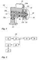
- Fig. 1 shows a drive 10 for a press comprising a servomotor 11, a toothed belt transmission 12, an intermediate shaft 18, a gear train 20 and an eccentric shaft 22.
- the eccentric shaft 22 forms the output shaft of the drive 10. It passes through an eccentric offset to the rotation axis center portion 22e pivotally a connecting rod 22p, which is rotatably connected at its end portion with a press ram 24.
- the output of the servomotor 11 is connected to the toothed belt transmission 12, which is formed of a motor pinion gear 12m, a toothed belt 12r and a toothed pulley 12s.
- the motor pinion 12m is penetrated by the output shaft of the servo motor 11 and connected to this torsionally rigid.
- the toothed disc 12s is arranged rotationally rigidly on the intermediate shaft 18. In this way, the rotational movement of the output shaft of the servomotor 11 via the toothed belt 12r, which wraps around the motor pinion 12m and the toothed disc 12s, transmitted without slip on the intermediate shaft 18.
- the servomotor 11 functions not only as a drive motor but also as a brake. When the servomotor 11 is operated as a brake, it forms an electrical generator and returns kinetic energy stored in the rotating components of the drive 10 as electrical energy to the electric network feeding it, so that the average energy requirement of the servomotor 11 can be less than its peak energy requirement.
- the term servomotor here also includes a so-called torque motor, which has a higher torque at low speed than the known servomotors. The maximum speed of the torque motor is designed to be lower than that of the servomotor. It may therefore be provided instead of the servomotor, a torque motor.
- the intermediate shaft 18 engages with its output section, the drive pinion of the gear train 20, which is only indicated in the schematic sectional view in Fig. 1, and is connected to this torsionally rigid.
- the output gear of the gear train 20 is penetrated by the drive section of the eccentric shaft 22 and connected to it torsionally rigid.
- the gear train 20 is connected between intermediate shaft 18 and eccentric shaft 22 and provided for speed reduction.
- an intermediate gear which is preferably designed as a gear transmission.
- a different type of transmission may be provided instead of the gear train. It can also be provided to omit the gear mechanism 20, in particular if a torque motor is provided as the drive motor.
- the toothed belt transmission 12 has in this embodiment primarily the task to form the drive 10 as a compact assembly and allows the arrangement of the servo motor 11 via the intermediate shaft 18, because the timing belt 12r bridges the parallel offset between the output shaft of the servo motor 11 and the intermediate shaft 18.
- the eccentric middle section 22e of the eccentric shaft 22 forms, with the connecting rod 22p, an assembly which converts the rotary drive movement of the servomotor 11 into a translatory movement of the press ram 24.
- the output side end portion of the connecting rod is rotatable with the upper end portion of the Press ram 24 connected.
- the flywheel 16 is rotatably arranged on the end remote from the gear train 20 end portion of the intermediate shaft 18.
- the flywheel 16 is rotatably connected via the clutch 14 to the intermediate shaft 18 switchable.
- the drive of the clutch 14 is arranged rotationally fixed on the intermediate shaft 18 and the output of the clutch 14 is rotationally rigidly connected to the flywheel 16.
- the flywheel 16 can be connected switchable torsionally rigid with the intermediate shaft 18 and are rotated by the drive 10 in rotation. Due to the rotational energy stored in the rotating flywheel 16, the flywheel 16 is able to deliver energy thereto upon loading of the drive 10 and thus stabilize the speed of the drive 10, i. the rotational speed of the eccentric shaft 22 is stabilized.
- the toothed disc 12s, the clutch 14 and the flywheel 16 are arranged in the illustrated embodiment without lateral play on the intermediate shaft 18.
- the direction of the power flow is indicated by arrows, with continuous arrows for the power flow from the servo motor 11 to the press ram 24 - in the following referred to as Hauptkraftfluß - and with broken arrows representing the flow of power from a component of the drive 10 to the flywheel 16 and the return of kinetic energy stored in the rotating flywheel 16 - hereinafter referred to as Maukraftfluß - to this component of the drive 10.
- Die Components of the drive 10 are summarized for better clarity by an interrupted boundary line.
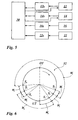
- Fig. 2 illustrates the flow of force between the components of the drive 10 and the clutch / flywheel assembly 14, 16 for the first embodiment in Fig. 1.
- the same elements are designated by the same positions.
- the main power flow is directed from the output of the servomotor 11 via the toothed belt transmission 12, the gear train 20 and the eccentric shaft 22 on the press ram 24, which is set in this way in a downward movement.
- the Superkraftfluß is directed via the clutch 14 to the flywheel 16, which is charged in this way with kinetic energy.
- Fig. 3 shows a second embodiment of the coupling of the assembly clutch / flywheel 14, 16 to the drive 10.
- the clutch 14 is now connected to the output of the servomotor 11.
- the main power flow is unchanged from the first embodiment shown in FIG.
- the Superkraftfluß is now directed by the output of the servo motor 11 via the clutch 14 to the flywheel 16.
- the secondary power flow is directed to the press ram 24 via the clutch 14, the toothed belt transmission 12, the gear train 20 and the eccentric shaft 22.
- the Finekraftfluß is directed via the clutch 14 and the eccentric shaft 22 on the press ram 24.
- the assembly clutch / flywheel 14, 16 can be connected to different elements of the drive 10.
- the kinetic energy storable in the flywheel 16 is proportional to the square of the rotational speed and the moment of inertia of the flywheel 16.
- the arrangement may be provided in Fig. 3. In this case, it may further be provided to concentrate the mass of the flywheel 16 on the circumference of the flywheel, i. to form the flywheel substantially with T-shaped cross-section.
- the arrangement in FIG. 4 can be provided.
- the disadvantage, however, is the necessary high mass of the flywheel 16 to save enough energy despite low speed.
- the arrangement in FIG. 2 is designed as a compromise and can therefore be particularly preferred.
- Fig. 5 is a block diagram of the control of the embodiment shown in Fig. 1.
- the sensors may be internal sensors 11s of the servomotor 11, one or more sensors 14s connected to the clutch 14, one or more sensors 16s connected to the flywheel 16, and one or more sensors 22s connected to the eccentric shaft 22.
- the sensors 16s and 22s may preferably be absolute rotary encoders, for example formed as a code disk scanned with laser light.
- the sensor or sensors 11 s of the servomotor 11 are sensors integrated into the motor, which are provided for control of the rotational angle of the servomotor.
- brake elements may be provided to bring in case of failure moving elements, such as the eccentric shaft 22 and / or the flywheel 16 to a halt, or it may be provided that components of the drive 10, such as the servo motor 11, designed as a braking element are.
- FIG. 6 is used with reference to the embodiment shown in FIGS. 1, 2 and 5.
- FIG. 6 shows in a circular diagram a circular path 32 which travels an imaginary point on the circumference of the eccentric middle section 22e of the eccentric shaft 22.
- the uppermost position of the circular path 32 is referred to as top dead center OT and the lowest position of the circular path 32 as bottom dead center UT.
- the press ram 24 occupies corresponding layers, i. he takes in top dead center OT its top position and bottom dead center UT its lowest position.
- S 1 to S 6 Other prominent points of the circular path 32 are designated by S 1 to S 6 .
- the drive operates with a cyclic sequence, as described below.
- the control device 30 outputs a signal for actuating the clutch 14, ie for engaging.
- the point S 2 denotes the completion of the electrical control of the clutch 14, accordingly, the angle W 1 denotes the angle of rotation, the eccentric shaft 22 covers until the electrical control of the clutch 14 is completed, ie the clutch is now engaged.
- the mechanical actuation of the clutch 14 is initiated, which is completed upon reaching the point S 3 .
- the angle W 2 denotes the angle of rotation, which covers the eccentric shaft 22 until the mechanical actuation of the clutch 14 is completed.
- the working angle designated W A begins, which is completed at the bottom dead center UT.
- the flywheel 16 is a part of its rotational energy.
- the flywheel 16 acts as an additional source of energy for the servo motor 11, which alone is not able to provide the energy for the running at operating angle W A power stroke. Due to the energy output, the rotational speed of the flywheel 16 and of the servomotor 11 rotatably connected to the flywheel 16 via the clutch 14 and the toothed belt drive 12 is reduced.
- the control device 30 now controls the servomotor 11 to the working speed, which it assumes in good time before reaching the point S 4 .
- the electrical actuation of the clutch 14 begins to separate the flywheel 16 from the intermediate shaft 18, which is completed at point S 5 , and followed by the mechanical activation of the clutch 14 for disengaging, which is completed at point S 6 .
- the corresponding angles are designated in Fig. 6 with W 3 and W 4 .
- W E the angle between the points S 3 to S 5 is designated by W E , in which the flywheel 16 is supplied with drive energy.
- the servomotor 11 now accelerates the drive 10, which is separate from the flywheel 16, to the transport speed, which is higher than the working speed, so that the path outside the working angle W A is covered more rapidly.
- the control device 30 the optimal transport speed, for example, from the accelerated rotational masses, the vohandenen maximum engine torque, the gear ratio of the gear train 20, the permissible maximum speed of the eccentric shaft 22 and the available free crank angle W F calculated. But it can also be provided that the maximum transport speed is specified by the operator.
- the controller 30 Shortly before reaching point S 1 , the controller 30 returns the servomotor 11 to the engine speed required for the working speed.
- the servomotor 11 now operates as an electrical generator so that energy can be returned to the electronic network. In this way it can be achieved that the total energy consumption of the servomotor 11 is only slightly higher than that of a constant speed rotating conventional drive motor with lower power consumption.
- the control device 30 determines based on sensor signals, for example, the signals of the sensor 14s of the clutch 14, whether the two halves of the clutch 14 rotate at the same peripheral speed. If necessary, the controller 30 corrects the rotational speed of the servomotor 11. Now, the clutch 14 is engaged. Because of the synchronous speed of both halves of the clutch 14, no frictional wear occurs in the clutch.
- the starting process can proceed as follows: At the beginning of a drive cycle, the flywheel 16 is at rest and the clutch 14 connects the flywheel 16 with the intermediate shaft 18, so that the flywheel 16 is rotationally rigidly connected to the intermediate shaft 18.
- the flywheel 16 is now accelerated by the servo motor 11 from zero speed to the working speed. This acceleration phase may last a few revolutions of the eccentric shaft 22. Punching or forming operations are already performed with increasing number of cycles.
- the eccentric shaft 22 has reached the working speed for the first time after passing through the bottom dead center UT, the starting operation of the drive 10 is completed. Now the flywheel 16 can be decoupled, the cycle begins.
- FIG. 7 now shows, with reference to FIG. 3, the block diagram of the force flow for a fourth embodiment variant with an auxiliary drive 40.
- the auxiliary drive 40 is formed from an additional motor 41, which can be connected to the flywheel 16 via a switchable additional clutch 44.
- the directed by the auxiliary drive 40 to the flywheel 16 power flow is indicated by dotted arrows.
- the auxiliary motor 41 may be temporarily connected to start the flywheel 16 connected to the flywheel 16, so that the servo motor 11 of the drive 10 is provided only for starting the drive 10.
- the auxiliary motor 41 may also be permanently connected to the flywheel 16. It can therefore be provided that the additional drive 40 is formed without additional coupling 44. In this way, the servo motor 11 of the drive 10 can be relieved because the auxiliary motor 41 accelerates the flywheel 16 after the forming process back to working speed. Thus, it provides the flywheel 16 taken during the forming kinetic energy immediately after passing through the bottom dead center UT and keeps the speed of the flywheel 16 constant, while the servo motor 11 can accelerate the eccentric shaft 22 directly after passing the bottom dead center UT to the transport speed.
- the auxiliary motor 41 is designed as a servomotor. Such an embodiment is particularly advantageous controllable in their speed.
- the target speed of the additional motor 41 is equal to the speed of the flywheel 16, which occupies it at the working speed of the eccentric shaft 22.
- the flywheel 16 is already decoupled after passing the bottom dead center UT (see Fig. 6) from the drive 10 and the servo motor 11 immediately thereafter accelerates the drive to the transport speed. In this way, the cycle time of the drive 10 with respect to the embodiment shown in FIGS. 1 and 3 can be reduced.
- the auxiliary drive 40 thus compensates the speed or energy losses of the flywheel 16 and / or drives the flywheel 16 from standstill high.
- the auxiliary drive 40 is used in case of failure of festgerionenen drive 10.
- the flywheel 16 is separated from the drive 10 and is first raised with the help of the auxiliary drive with opposite to the normal direction of rotation. It is briefly connected after startup by coupling the clutch 14 to the drive 10. In this way, the stuck drive 10 is "broken off”.
- the inventive method for controlling the press drive 10 thus combines the advantages of direct drive by means of a servomotor without flywheel with those of conventional flywheel drive by providing a drive with low moment of inertia for the transport phase and provides for the working phase a drive with high moment of inertia. Another advantage is the fact that the engagement of the flywheel is performed free of load and wear.
Landscapes
- Engineering & Computer Science (AREA)
- Mechanical Engineering (AREA)
- Press Drives And Press Lines (AREA)
Priority Applications (3)
| Application Number | Priority Date | Filing Date | Title |
|---|---|---|---|
| ES04022983T ES2289409T3 (es) | 2004-09-27 | 2004-09-27 | Accionamiento directo y control para una prensa excentrica. |
| EP20040022983 EP1640145B1 (fr) | 2004-09-27 | 2004-09-27 | Entraînement direct et régulation pour presse à excentrique |
| DE200450004148 DE502004004148D1 (de) | 2004-09-27 | 2004-09-27 | Direktantrieb und Steuerung für eine Exzenterpresse |
Applications Claiming Priority (1)
| Application Number | Priority Date | Filing Date | Title |
|---|---|---|---|
| EP20040022983 EP1640145B1 (fr) | 2004-09-27 | 2004-09-27 | Entraînement direct et régulation pour presse à excentrique |
Publications (2)
| Publication Number | Publication Date |
|---|---|
| EP1640145A1 true EP1640145A1 (fr) | 2006-03-29 |
| EP1640145B1 EP1640145B1 (fr) | 2007-06-20 |
Family
ID=34926735
Family Applications (1)
| Application Number | Title | Priority Date | Filing Date |
|---|---|---|---|
| EP20040022983 Expired - Lifetime EP1640145B1 (fr) | 2004-09-27 | 2004-09-27 | Entraînement direct et régulation pour presse à excentrique |
Country Status (3)
| Country | Link |
|---|---|
| EP (1) | EP1640145B1 (fr) |
| DE (1) | DE502004004148D1 (fr) |
| ES (1) | ES2289409T3 (fr) |
Cited By (13)
| Publication number | Priority date | Publication date | Assignee | Title |
|---|---|---|---|---|
| WO2007091935A1 (fr) * | 2006-02-06 | 2007-08-16 | Abb Research Ltd | Systeme de pilotage de presse mecanique |
| WO2007091118A1 (fr) * | 2006-02-06 | 2007-08-16 | Abb Research Ltd | Systeme d'entrainement de presse mecanique et procede |
| EP1930149A1 (fr) * | 2006-12-05 | 2008-06-11 | Burkhardt GmbH Maschinenfabrik | Entrainement pour presse à excentrique |
| WO2008119686A1 (fr) * | 2007-04-02 | 2008-10-09 | Bifrangi S.P.A. | Presse à forger horizontale améliorée |
| EP2006080A1 (fr) * | 2007-06-21 | 2008-12-24 | Abb Research Ltd. | Procédé et dispositif de contrôle d'une presse mécanique |
| WO2010004062A2 (fr) | 2008-07-08 | 2010-01-14 | Goizper, S. Coop. | Dispositif de frein et embrayage combiné pour presses |
| EP2186631A1 (fr) | 2008-11-12 | 2010-05-19 | FMI systems GmbH | Bancs de formage dotés d'un mode de fonctionnement efficace |
| WO2012055558A1 (fr) * | 2010-10-27 | 2012-05-03 | Schuler Pressen Gmbh | Machine de formage mécanique, en particulier presse à vilebrequin, ainsi que procédé de réalisation d'une machine de formage mécanique |
| US20140083313A1 (en) * | 2012-09-27 | 2014-03-27 | Schuler Pressen Gmbh | Method and device for operating a machine tool such as a press with a linearly movable stroke element |
| EP2152505B1 (fr) * | 2007-06-06 | 2015-07-29 | ABB Research LTD | Kit d'amélioration de moteur pour une presse mécanique |
| DE102015222995A1 (de) * | 2015-11-20 | 2017-05-24 | Sms Group Gmbh | Weggebundene Presse mit Kulissenstein |
| US10499639B2 (en) | 2014-03-26 | 2019-12-10 | Jiangsu Rotam Chemistry Co., Ltd. | Herbicidal composition, a method for its preparation and the use thereof |
| CN111859661A (zh) * | 2020-07-17 | 2020-10-30 | 西门子(中国)有限公司 | 压力机偏心机构的惯量确定方法 |
Citations (6)
| Publication number | Priority date | Publication date | Assignee | Title |
|---|---|---|---|---|
| DE884278C (de) * | 1941-07-17 | 1953-07-27 | Weingarten Ag Maschf | Mechanische Presse, insbesondere Ziehpresse |
| DE1294809B (de) * | 1961-01-14 | 1969-05-08 | Pressen Und Scherenbau Erfurt | Pressenantrieb mit verschiedenen Arbeitsgeschwindigkeiten fuer mechanische Pressen, insbesondere Ziehpressen |
| DE4109796A1 (de) * | 1991-03-26 | 1992-10-01 | Georg Burger | Einrichtung zum pressen, biegen und/oder stanzen |
| US5832816A (en) * | 1995-12-15 | 1998-11-10 | Amada Mfg America Inc. | Ram driving device and press machine using same |
| US20040003729A1 (en) * | 2002-07-04 | 2004-01-08 | Komatsu Artec Ltd. | Drive unit and drive method for press |
| WO2004056559A1 (fr) * | 2002-12-19 | 2004-07-08 | Siemens Aktiengesellschaft | Dispositif de compression |
-
2004
- 2004-09-27 DE DE200450004148 patent/DE502004004148D1/de not_active Expired - Lifetime
- 2004-09-27 ES ES04022983T patent/ES2289409T3/es not_active Expired - Lifetime
- 2004-09-27 EP EP20040022983 patent/EP1640145B1/fr not_active Expired - Lifetime
Patent Citations (6)
| Publication number | Priority date | Publication date | Assignee | Title |
|---|---|---|---|---|
| DE884278C (de) * | 1941-07-17 | 1953-07-27 | Weingarten Ag Maschf | Mechanische Presse, insbesondere Ziehpresse |
| DE1294809B (de) * | 1961-01-14 | 1969-05-08 | Pressen Und Scherenbau Erfurt | Pressenantrieb mit verschiedenen Arbeitsgeschwindigkeiten fuer mechanische Pressen, insbesondere Ziehpressen |
| DE4109796A1 (de) * | 1991-03-26 | 1992-10-01 | Georg Burger | Einrichtung zum pressen, biegen und/oder stanzen |
| US5832816A (en) * | 1995-12-15 | 1998-11-10 | Amada Mfg America Inc. | Ram driving device and press machine using same |
| US20040003729A1 (en) * | 2002-07-04 | 2004-01-08 | Komatsu Artec Ltd. | Drive unit and drive method for press |
| WO2004056559A1 (fr) * | 2002-12-19 | 2004-07-08 | Siemens Aktiengesellschaft | Dispositif de compression |
Cited By (20)
| Publication number | Priority date | Publication date | Assignee | Title |
|---|---|---|---|---|
| WO2007091118A1 (fr) * | 2006-02-06 | 2007-08-16 | Abb Research Ltd | Systeme d'entrainement de presse mecanique et procede |
| US7805973B2 (en) | 2006-02-06 | 2010-10-05 | Abb Research Ltd. | Mechanical press drive system |
| WO2007091935A1 (fr) * | 2006-02-06 | 2007-08-16 | Abb Research Ltd | Systeme de pilotage de presse mecanique |
| US8302452B2 (en) | 2006-02-06 | 2012-11-06 | Abb Research Ltd. | Mechanical press drive system and method |
| EP1930149A1 (fr) * | 2006-12-05 | 2008-06-11 | Burkhardt GmbH Maschinenfabrik | Entrainement pour presse à excentrique |
| WO2008119686A1 (fr) * | 2007-04-02 | 2008-10-09 | Bifrangi S.P.A. | Presse à forger horizontale améliorée |
| EP2152505B1 (fr) * | 2007-06-06 | 2015-07-29 | ABB Research LTD | Kit d'amélioration de moteur pour une presse mécanique |
| EP2006080A1 (fr) * | 2007-06-21 | 2008-12-24 | Abb Research Ltd. | Procédé et dispositif de contrôle d'une presse mécanique |
| WO2008155190A1 (fr) * | 2007-06-21 | 2008-12-24 | Abb Research Ltd. | Procédé et appareil de commande d'une presse mécanique |
| WO2010004062A2 (fr) | 2008-07-08 | 2010-01-14 | Goizper, S. Coop. | Dispositif de frein et embrayage combiné pour presses |
| EP2186631A1 (fr) | 2008-11-12 | 2010-05-19 | FMI systems GmbH | Bancs de formage dotés d'un mode de fonctionnement efficace |
| WO2010054626A1 (fr) * | 2008-11-12 | 2010-05-20 | Fmi Systems Gmbh | Machines de formage à mode de fonctionnement efficace |
| WO2012055558A1 (fr) * | 2010-10-27 | 2012-05-03 | Schuler Pressen Gmbh | Machine de formage mécanique, en particulier presse à vilebrequin, ainsi que procédé de réalisation d'une machine de formage mécanique |
| US9350212B2 (en) | 2010-10-27 | 2016-05-24 | Schuler Pressen Gmbh | Mechanical metal-forming machine having a flywheel coupled to a rotor of an auxiliary drive and method for providing the mechanical metal-forming machine |
| DE102012109150A1 (de) * | 2012-09-27 | 2014-03-27 | Schuler Pressen Gmbh | Verfahren und Einrichtung zum Betreiben einer Werkzeugmaschine wie Presse mit linear bewegbarem Hubelement |
| US20140083313A1 (en) * | 2012-09-27 | 2014-03-27 | Schuler Pressen Gmbh | Method and device for operating a machine tool such as a press with a linearly movable stroke element |
| US10499639B2 (en) | 2014-03-26 | 2019-12-10 | Jiangsu Rotam Chemistry Co., Ltd. | Herbicidal composition, a method for its preparation and the use thereof |
| DE102015222995A1 (de) * | 2015-11-20 | 2017-05-24 | Sms Group Gmbh | Weggebundene Presse mit Kulissenstein |
| CN111859661A (zh) * | 2020-07-17 | 2020-10-30 | 西门子(中国)有限公司 | 压力机偏心机构的惯量确定方法 |
| CN111859661B (zh) * | 2020-07-17 | 2023-07-14 | 西门子(中国)有限公司 | 压力机偏心机构的惯量确定方法 |
Also Published As
| Publication number | Publication date |
|---|---|
| ES2289409T3 (es) | 2008-02-01 |
| EP1640145B1 (fr) | 2007-06-20 |
| DE502004004148D1 (de) | 2007-08-02 |
Similar Documents
| Publication | Publication Date | Title |
|---|---|---|
| EP1640145B1 (fr) | Entraînement direct et régulation pour presse à excentrique | |
| EP1610038B1 (fr) | Transmission à double embrayage et methode de controle d'une transmission à double embrayage | |
| EP0832370B1 (fr) | Systeme de commande d'embrayage automatique | |
| DE69521866T2 (de) | Automatisierte Kupplungsbetätigung und -Einstellung | |
| DE102006013040B4 (de) | Kupplungssteuervorrichtung | |
| EP0088150B1 (fr) | Agencement d'une transmission mécanique à changement de vitesse sous charge | |
| WO2000026552A2 (fr) | Vehicule automobile pourvu d'un systeme de reconnaissance d'une intention de changement de vitesse | |
| WO2007039103A1 (fr) | Moteur a combustion presentant un taux de compression variable | |
| WO2015144148A1 (fr) | Procédé de détermination d'un mode de fonctionnement d'un actionneur à un seul moteur pour boîte de vitesses | |
| DE102006027039A1 (de) | Elektromechanischer Bremskraftverstärker | |
| DE112011102280T5 (de) | Kupplungsbetätigungsvorrichtung | |
| EP1930149A1 (fr) | Entrainement pour presse à excentrique | |
| WO2000075536A1 (fr) | Procede pour faire fonctionner une unite d'actionnement d'une boite de vitesse automatisee | |
| EP1763601B1 (fr) | Dispositif d'entrainement pour un metier a tisser | |
| DE1236948B (de) | Schaltanordnung fuer ein Geschwindigkeits-wechselgetriebe mit mehreren Gaengen fuer Kraftfahrzeuge | |
| EP2326805B1 (fr) | Procédé pour le calage d'un vilebrequin d'un moteur à combustion interne, système de déphasage d'arbre à cames et moteur à combustion interne à vilebrequin calable | |
| DE3513279C2 (de) | Automatische Gangschalteinrichtung | |
| WO2010012764A1 (fr) | Procédé permettant d'engrener un pignon de démarrage d'un dispositif de démarrage dans une couronne dentée d'un moteur à combustion interne | |
| EP1894708A1 (fr) | Dispositif d'entrainement pour une presse, une presse de poinçonnage ou un dispositif de formage | |
| DE19916169A1 (de) | Stelleinrichtung und Stellglied für diese | |
| DE60008626T2 (de) | Steuereinrichtung und Verfahren zum Schalten von Automatikgetrieben | |
| EP4295062A1 (fr) | Boîte de vitesses à vitesse variable équipée d'un tambour de changement de vitesse entraîné par moteur électrique et procédé de commande d'une telle boîte de vitesses à vitesse variable | |
| DE102011051859B4 (de) | Einrichtung zum synchronisierten Schalten einer Kupplung, insbesondere einer Zahnkupplung eines Fahrzeuges | |
| DE202011050731U1 (de) | Einrichtung zum synchronisierten Schalten einer Kupplung, insbesondere einer Zahnkupplung eines Fahrzeuges | |
| DE19851466A1 (de) | Stellglied |
Legal Events
| Date | Code | Title | Description |
|---|---|---|---|
| PUAI | Public reference made under article 153(3) epc to a published international application that has entered the european phase |
Free format text: ORIGINAL CODE: 0009012 |
|
| 17P | Request for examination filed |
Effective date: 20050617 |
|
| AK | Designated contracting states |
Kind code of ref document: A1 Designated state(s): AT BE BG CH CY CZ DE DK EE ES FI FR GB GR HU IE IT LI LU MC NL PL PT RO SE SI SK TR |
|
| AX | Request for extension of the european patent |
Extension state: AL HR LT LV MK |
|
| GRAP | Despatch of communication of intention to grant a patent |
Free format text: ORIGINAL CODE: EPIDOSNIGR1 |
|
| GRAS | Grant fee paid |
Free format text: ORIGINAL CODE: EPIDOSNIGR3 |
|
| AKX | Designation fees paid |
Designated state(s): CH DE ES IT LI |
|
| GRAA | (expected) grant |
Free format text: ORIGINAL CODE: 0009210 |
|
| AK | Designated contracting states |
Kind code of ref document: B1 Designated state(s): CH DE ES IT LI |
|
| REG | Reference to a national code |
Ref country code: CH Ref legal event code: EP |
|
| REF | Corresponds to: |
Ref document number: 502004004148 Country of ref document: DE Date of ref document: 20070802 Kind code of ref document: P |
|
| REG | Reference to a national code |
Ref country code: CH Ref legal event code: NV Representative=s name: FIAMMENGHI-FIAMMENGHI |
|
| REG | Reference to a national code |
Ref country code: ES Ref legal event code: FG2A Ref document number: 2289409 Country of ref document: ES Kind code of ref document: T3 |
|
| PLBE | No opposition filed within time limit |
Free format text: ORIGINAL CODE: 0009261 |
|
| STAA | Information on the status of an ep patent application or granted ep patent |
Free format text: STATUS: NO OPPOSITION FILED WITHIN TIME LIMIT |
|
| 26N | No opposition filed |
Effective date: 20080325 |
|
| PGFP | Annual fee paid to national office [announced via postgrant information from national office to epo] |
Ref country code: CH Payment date: 20100923 Year of fee payment: 7 Ref country code: ES Payment date: 20100921 Year of fee payment: 7 |
|
| PGFP | Annual fee paid to national office [announced via postgrant information from national office to epo] |
Ref country code: IT Payment date: 20100924 Year of fee payment: 7 |
|
| PGFP | Annual fee paid to national office [announced via postgrant information from national office to epo] |
Ref country code: DE Payment date: 20100701 Year of fee payment: 7 |
|
| REG | Reference to a national code |
Ref country code: CH Ref legal event code: PL |
|
| PG25 | Lapsed in a contracting state [announced via postgrant information from national office to epo] |
Ref country code: IT Free format text: LAPSE BECAUSE OF NON-PAYMENT OF DUE FEES Effective date: 20110927 |
|
| REG | Reference to a national code |
Ref country code: DE Ref legal event code: R119 Ref document number: 502004004148 Country of ref document: DE Effective date: 20120403 |
|
| PG25 | Lapsed in a contracting state [announced via postgrant information from national office to epo] |
Ref country code: DE Free format text: LAPSE BECAUSE OF NON-PAYMENT OF DUE FEES Effective date: 20120403 Ref country code: LI Free format text: LAPSE BECAUSE OF NON-PAYMENT OF DUE FEES Effective date: 20110930 Ref country code: CH Free format text: LAPSE BECAUSE OF NON-PAYMENT OF DUE FEES Effective date: 20110930 |
|
| REG | Reference to a national code |
Ref country code: ES Ref legal event code: FD2A Effective date: 20130417 |
|
| PG25 | Lapsed in a contracting state [announced via postgrant information from national office to epo] |
Ref country code: ES Free format text: LAPSE BECAUSE OF NON-PAYMENT OF DUE FEES Effective date: 20110928 |