EP1639905A1 - Vorrichtung zum Brechen von öligen Massen, insbesondere von pflanzlichem, öligen Fruchtfleisch sowie Verfahren hierfür - Google Patents
Vorrichtung zum Brechen von öligen Massen, insbesondere von pflanzlichem, öligen Fruchtfleisch sowie Verfahren hierfür Download PDFInfo
- Publication number
- EP1639905A1 EP1639905A1 EP04425707A EP04425707A EP1639905A1 EP 1639905 A1 EP1639905 A1 EP 1639905A1 EP 04425707 A EP04425707 A EP 04425707A EP 04425707 A EP04425707 A EP 04425707A EP 1639905 A1 EP1639905 A1 EP 1639905A1
- Authority
- EP
- European Patent Office
- Prior art keywords
- oily
- containment chamber
- scutching
- pulp
- pulps
- Prior art date
- Legal status (The legal status is an assumption and is not a legal conclusion. Google has not performed a legal analysis and makes no representation as to the accuracy of the status listed.)
- Withdrawn
Links
- 238000000034 method Methods 0.000 title claims description 11
- 235000013311 vegetables Nutrition 0.000 title 1
- 238000012545 processing Methods 0.000 claims description 14
- XLYOFNOQVPJJNP-UHFFFAOYSA-N water Substances O XLYOFNOQVPJJNP-UHFFFAOYSA-N 0.000 claims description 9
- 238000007599 discharging Methods 0.000 claims description 6
- 239000000523 sample Substances 0.000 claims description 2
- 230000002093 peripheral effect Effects 0.000 claims 2
- 230000005540 biological transmission Effects 0.000 claims 1
- 230000008901 benefit Effects 0.000 description 11
- IJGRMHOSHXDMSA-UHFFFAOYSA-N Atomic nitrogen Chemical compound N#N IJGRMHOSHXDMSA-UHFFFAOYSA-N 0.000 description 6
- 238000000605 extraction Methods 0.000 description 5
- 239000002245 particle Substances 0.000 description 5
- 230000008569 process Effects 0.000 description 5
- 230000009471 action Effects 0.000 description 4
- 230000000694 effects Effects 0.000 description 4
- 239000012530 fluid Substances 0.000 description 4
- 239000003921 oil Substances 0.000 description 4
- 240000007817 Olea europaea Species 0.000 description 3
- 238000004519 manufacturing process Methods 0.000 description 3
- 229910052757 nitrogen Inorganic materials 0.000 description 3
- 230000003647 oxidation Effects 0.000 description 3
- 238000007254 oxidation reaction Methods 0.000 description 3
- 238000003756 stirring Methods 0.000 description 3
- QVGXLLKOCUKJST-UHFFFAOYSA-N atomic oxygen Chemical compound [O] QVGXLLKOCUKJST-UHFFFAOYSA-N 0.000 description 2
- 230000008859 change Effects 0.000 description 2
- 238000004581 coalescence Methods 0.000 description 2
- 238000010276 construction Methods 0.000 description 2
- 230000008878 coupling Effects 0.000 description 2
- 238000010168 coupling process Methods 0.000 description 2
- 238000005859 coupling reaction Methods 0.000 description 2
- 239000000839 emulsion Substances 0.000 description 2
- 238000001704 evaporation Methods 0.000 description 2
- 230000008020 evaporation Effects 0.000 description 2
- 230000001747 exhibiting effect Effects 0.000 description 2
- 230000001339 gustatory effect Effects 0.000 description 2
- 230000006872 improvement Effects 0.000 description 2
- 238000012423 maintenance Methods 0.000 description 2
- 239000007800 oxidant agent Substances 0.000 description 2
- 239000001301 oxygen Substances 0.000 description 2
- 229910052760 oxygen Inorganic materials 0.000 description 2
- 238000009304 pastoral farming Methods 0.000 description 2
- 239000000126 substance Substances 0.000 description 2
- 210000003934 vacuole Anatomy 0.000 description 2
- 241000894006 Bacteria Species 0.000 description 1
- 241000207836 Olea <angiosperm> Species 0.000 description 1
- 239000003242 anti bacterial agent Substances 0.000 description 1
- 125000003118 aryl group Chemical group 0.000 description 1
- 230000000740 bleeding effect Effects 0.000 description 1
- 238000006243 chemical reaction Methods 0.000 description 1
- 238000010494 dissociation reaction Methods 0.000 description 1
- 230000005593 dissociations Effects 0.000 description 1
- 230000002255 enzymatic effect Effects 0.000 description 1
- 230000002538 fungal effect Effects 0.000 description 1
- 229910044991 metal oxide Inorganic materials 0.000 description 1
- 150000004706 metal oxides Chemical class 0.000 description 1
- 230000005012 migration Effects 0.000 description 1
- 238000013508 migration Methods 0.000 description 1
- 150000002978 peroxides Chemical class 0.000 description 1
- ISWSIDIOOBJBQZ-UHFFFAOYSA-N phenol group Chemical group C1(=CC=CC=C1)O ISWSIDIOOBJBQZ-UHFFFAOYSA-N 0.000 description 1
- 238000002360 preparation method Methods 0.000 description 1
- 102000004169 proteins and genes Human genes 0.000 description 1
- 108090000623 proteins and genes Proteins 0.000 description 1
- 229910001220 stainless steel Inorganic materials 0.000 description 1
- 239000010935 stainless steel Substances 0.000 description 1
- 238000003860 storage Methods 0.000 description 1
- 230000001629 suppression Effects 0.000 description 1
- 238000012360 testing method Methods 0.000 description 1
- 230000001960 triggered effect Effects 0.000 description 1
- 239000002351 wastewater Substances 0.000 description 1
Images


Classifications
-
- A—HUMAN NECESSITIES
- A23—FOODS OR FOODSTUFFS; TREATMENT THEREOF, NOT COVERED BY OTHER CLASSES
- A23N—MACHINES OR APPARATUS FOR TREATING HARVESTED FRUIT, VEGETABLES OR FLOWER BULBS IN BULK, NOT OTHERWISE PROVIDED FOR; PEELING VEGETABLES OR FRUIT IN BULK; APPARATUS FOR PREPARING ANIMAL FEEDING- STUFFS
- A23N1/00—Machines or apparatus for extracting juice
Definitions
- the present invention refers to an apparatus for the scutching of oily pulps and, more precisely, to an apparatus of the kind having a vertical processing chamber for the scutching of oily pulps like, e.g., olive pulp and the like.
- the first principle is mechanical, there being a mechanical action that, as the scutchers with their rotor stir the pulp, is exerted directly onto the oily particles; said action, owing to the principle of coalescence, reunites said particles in the form of ever greater droplets, thereby facilitating their extraction in horizontal centrifuge (decanter).
- the second principle is of enzymatic action, triggered on the pulp during the processing of the latter inside the scutcher. It is due both to the stirring of the pulp and to the fact that the environment internal to the scutcher is temperature-controlled, and therefore the pulp into contact with the heated walls of the apparatus reaches >25°C temperatures. At such a temperature, the vacuoles still retaining the oily particles begin to enzymatically dissolve the protein fraction, releasing the fluids that, owing to the mechanical principle, will coalesce into bigger droplets.
- a first drawback lies in that in order to attain a good pulp treatment efficiency the apparatus should operate always filled up with pulp topping the rotor level.
- a first kind of constructive solution provides the use of lids sealed onto the containment chamber in a manner such as to put the pulp in the scutcher under nitrogen.
- a solution entails the change of nitrogen and consequently a system for the self-production of nitrogen or another of filled cylinders. Therefore, both its production process and the maintenance thereof are highly onerous.
- organoleptic tests on the yielded product highlighted a suppression of the olfactory and gustatory notes.
- a second constructive solution disclosed in Italian patent No. 1307831, provides a scutcher in which the containment chamber has a vertical arrangement, rather than a horizontal one, in a manner such as to reduce the surface into contact with the oxidising agents contained in the air.
- object of the present invention is to solve the drawbacks highlighted hereto by providing an apparatus for the scutching of oily pulps, in which its effectiveness and efficiency be maximised, regardless from cultivars and sizes, moreover ensuring the absence of oxidising agents during the processing cycle.
- Another object of the present invention is to provide an apparatus for the scutching of oily pulps allowing the processing even of low quantities of oily pulp, maintaining the same efficiency with respect to the processing of large quantities of pulp.
- a further object of the present invention is to provide an apparatus for the scutching of oily pulps of simple construction, reliable, sturdy and of reasonable cost.
- the present invention provides an apparatus for the scutching of oily pulps according to claim 1. Moreover, the present invention provides a scutching method according to claim XX.
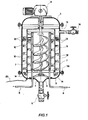
- a containment chamber 1 for the pulp to be treated vertically arranged and cylinder-shaped, having a hemispherical bottom 2 welded to the cylindrical wall of the chamber 1.
- the top wall of the chamber 1 has a hemispherical top cap 3 coupled to the cylindrical wall 1 by means of flanges drilled and bolted therebetween with the interposition of a rubber gasket.
- a flanged hole 4 is obtained, to house a vacuum-sealed butterfly valve 5.
- the valve 5 may be controlled automatically as well as manually.
- a drum 6 At the central region of the chamber 1 and above the hole 4 there is arranged a drum 6. Above the drum 6 there is fixedly mounted a vertically developing heat exchanger 7.
- the exchanger 7 is hollow and it has a double wall, which is internally connected to unions 8 thereof for supplying and discharging recycled hot water.
- the top cap 3 has a central hole provided with a flange to allow the coupling to a gearmotor 9. It ought to be specified that the flanged coupling between cap 3 and gearmotor 9 should be vacuum-sealed.
- the output of the gearmotor 9 is in turn coupled to a shaft supporting a rotor 10 arranged rotatably and coaxially inside the exchanger 7 (better illustrated hereinafter).
- the rotor is substantially implemented with a first Archimedean screw (or auger) 10, grazing the internal wall of the exchanger 7. Moreover, integrally to the rotor axis there are mounted a pair of arms 11 connected at their bottom ends by an annular element 110. The arrangement of the arms 11 is external to the exchanger 7 and on their internal and external surfaces they have a plurality of vanes or blades 12. The dimensions of the vanes 12 are such that, during the rotation of the arms 11, they graze the surface of the exchanger 7 and the surface of the chamber 1 (better illustrated hereinafter).
- the orientation of the vanes or blades 12 and 13 is such that during the rotation of the arms 11 the former convey the pulp toward the bottom of the chamber 1.
- the auger 10 At the bottom zone of the chamber 1 and onto the bottom edge of the annular element 110 there are mounted two or more conveying blades 14.
- the orientation of the blades 14 is such that during the rotation of the arms 11 the former convey the pulp toward the centre of the chamber 1 and below the exchanger 7.
- the auger 10 At the central region below the exchanger 7, the auger 10 has its spiral oriented in such a manner as to convey the pulp upward during its rotation.
- the auger 10 inside the exchanger 7, by rotating, provides the continual ascensional circulation of the pulp; thus, the fostering of the thermal exchange throughout all of the pulp is accelerated.
- This solution represents an improvement with respect to the apparatuses of the state of the art, in which the heat exchanger is provided onto the external wall of the apparatus. In fact, given the high distance of the wall from the centre of the apparatus, no homogeneous temperatures are obtained. In addition, the pulp needs not contact the walls for too long, risking to overheat it.
- the arrangement of the exchanger 7 inside the containment chamber 1 according to the present invention constitutes a remarkable improvement with respect to the known apparatuses, because the latter have as much exchange surface toward the pulp as toward the outside. This entails a low efficiency and a high calorie expenditure, whereas in the apparatus of the present invention all of the heat is transferred to the pulp.
- the exchanger 7 is contrived for the direct and pressurised exchange, requires no bleeding and has an electronically adjusted ON/OFF operation. This yields utmost efficiency and minimal energy expenditure.
- a supplying port 15 of the apparatus for the scutching is provided at the top portion of the cylindrical wall of the chamber 1.
- the port 15 is coupled to an union and to a vacuum-sealed butterfly valve 16. It has to be pointed out that the arrangement of the port 15 is such that the same also acts as overflow indicator, as the feeding of the pulp toward the inside of the chamber 1 instantly stops when the port 15 is obstructed by the pulp.
- the apparatus entails the following additional operation services.
- a line 17 for supplying blown air and a line 18 for extracting air connected to a vacuum pump to make the vacuum required for the pulp processing step and for the subsequent emptying of the chamber 1.
- both the inletting and the discharging of the pulp takes place without the aid of any pump whatsoever.
- inletting the pulp it is provided the use of the vacuum made in the scutcher, whereas for discharging the former it is provided the inletting of pressurised clean air from a dry blower.
- This enables to adjust the pulp flow rate (litres/hour) toward the decanter depending on the pressure used.
- an additional advantage lies in preventing the re-emulsifying effect commonly exhibited by pumps, due to their high speed of rotation.
- pressurised water line 19 allows to inlet water in the scutcher for a final rinsing, or for a total emptying in case of use for individual batches.
- the inlet and outlet for the pulp of the scutcher of the present invention it is provided the application of a permanent-charge magnet having a 12000 Gauss charge at a section of the supplying pipe and of the discharge pipe, respectively.
- the magnet applied at the inlet will lower the surface tension of the water, thereby further fostering the migration of the oily particles, whereas at the discharge the former, besides from continuing its action with regard to the water, will act as antibacterial agent, deactivating fungal activities by exploding the spores.
- the process wastewaters will be less polluting and the extracted oil will be of higher quality, as the use of the magnets in no way prejudices oil features.
- the apparatus for the scutching of the present invention entails several advantages.
- a first advantage lies in that the degree and the time of vacuum can be adjustable. Hence, it is possible to select the quantities of aromatic substances to be extracted, thereby customizing the olfactory and gustatory notes; in addition, the maximum extraction of phenolic substances will be ensured at all times.
- a second advantage lies in that it is entirely made of stainless steel and hence, not being potentially polluting with metal oxides, it preserves the mechanical effect, accordingly fostering coalescence even in case of a partially filled scutcher. Moreover, an ensuing advantage lies in that owing to the absence of oxygen no mould nor bacteria will ever nestle inside the scutcher, and the pulp will exhibit a markedly reduced rate of peroxides.
- a third advantage lies in that, given the specific arrangement of the auger 10 and of the arms 11 between the exchanger 7, a uniform thermal exchange is ensured even in case of a partially filled containment chamber 1.
- Another advantage lies in that the processing under hard vacuum ensures the absence of oxygen and therefore the absence of chemically oxidising actions. This entails that the pulp may stay inside the apparatus even for very long times, it being unaffected thereby.
- a further advantage lies in that vacuum enhances the extraction effect.
- the physical principle causes the most resilient vacuoles to implode due to vacuum, thereby releasing the fluids.
- vacuum fosters the dissociation of air from the emulsion and the evaporation of the water.
- Another advantage lies in that the process entails an elevated efficiency, given the more effective mechanical effect and the time surely much lower than that of a traditional scutcher.
- a further advantage lies in that the apparatus of the present invention so contrived, besides from being a real conversion to top-quality extraction even from pitted olives, which to date are difficult to scutch due to the lack of pit, provides maximum versatility also in extractive capacity.
- the desired result in terms of extractive capacity will equally be attained, yet in no way prejudicing the product as all will take place under conditions allowing no oily pulp oxidation whatsoever.
- the apparatus enables processing providing top-quality extra virgin oils, in conjunction with olive pitting systems already per se yielding high-quality oils, yet exhibiting a scutching problem.
- a further advantage lies in that the implementation costs thereof are equal to or lower than those of a traditional scutcher, the scutching times are greatly reduced, and the preparation of the pulp for the next step is much more effective.
Landscapes
- Life Sciences & Earth Sciences (AREA)
- Chemical & Material Sciences (AREA)
- Engineering & Computer Science (AREA)
- Food Science & Technology (AREA)
- Polymers & Plastics (AREA)
- Paper (AREA)
Priority Applications (1)
| Application Number | Priority Date | Filing Date | Title |
|---|---|---|---|
| EP04425707A EP1639905A1 (de) | 2004-09-23 | 2004-09-23 | Vorrichtung zum Brechen von öligen Massen, insbesondere von pflanzlichem, öligen Fruchtfleisch sowie Verfahren hierfür |
Applications Claiming Priority (1)
| Application Number | Priority Date | Filing Date | Title |
|---|---|---|---|
| EP04425707A EP1639905A1 (de) | 2004-09-23 | 2004-09-23 | Vorrichtung zum Brechen von öligen Massen, insbesondere von pflanzlichem, öligen Fruchtfleisch sowie Verfahren hierfür |
Publications (1)
| Publication Number | Publication Date |
|---|---|
| EP1639905A1 true EP1639905A1 (de) | 2006-03-29 |
Family
ID=34932775
Family Applications (1)
| Application Number | Title | Priority Date | Filing Date |
|---|---|---|---|
| EP04425707A Withdrawn EP1639905A1 (de) | 2004-09-23 | 2004-09-23 | Vorrichtung zum Brechen von öligen Massen, insbesondere von pflanzlichem, öligen Fruchtfleisch sowie Verfahren hierfür |
Country Status (1)
| Country | Link |
|---|---|
| EP (1) | EP1639905A1 (de) |
Cited By (8)
| Publication number | Priority date | Publication date | Assignee | Title |
|---|---|---|---|---|
| WO2007123499A1 (en) * | 2006-04-25 | 2007-11-01 | Zeynep Gurguc | Pulp production mill for high quality olive oil |
| USD684010S1 (en) | 2012-12-05 | 2013-06-11 | Sensio Inc. | Kitchen appliance base |
| USD688519S1 (en) | 2012-12-05 | 2013-08-27 | Sensio Inc. | Kitchen appliance bowl |
| USD698210S1 (en) | 2012-02-27 | 2014-01-28 | Sensio Inc. | Juicing machine |
| USD713216S1 (en) | 2012-12-05 | 2014-09-16 | Sensio Inc. | Filter |
| CN105768116A (zh) * | 2016-04-13 | 2016-07-20 | 长葛市吉庆机械厂 | 一种水果无氧榨汁装置 |
| IT201800007016A1 (it) * | 2018-07-06 | 2020-01-06 | Gramolatrice per frantoio oleario e relativo metodo di funzionamento | |
| CN118752834A (zh) * | 2024-08-15 | 2024-10-11 | 安徽省凤阳县御膳油脂有限公司 | 一种低温芝麻油的压榨设备及其工作方法 |
Citations (4)
| Publication number | Priority date | Publication date | Assignee | Title |
|---|---|---|---|---|
| ES344207A1 (es) * | 1967-08-18 | 1968-09-16 | Prado Santaella | Extractor continuo de aceite de oliva. |
| GB2064574A (en) * | 1979-12-01 | 1981-06-17 | Simon Rosedowns Ltd | Apparatus for the expansion of oil bearing seeds |
| EP0967264A1 (de) * | 1998-06-25 | 1999-12-29 | Toulousaine de Recherche et de Developpement "T.R.D." | Verfahren und Vorrichtung zur Extraktion von Öl aus Ölsaaten |
| WO2003099975A1 (es) * | 2002-05-28 | 2003-12-04 | Josep Sallent Soler | Proceso continuo para la obtencion de aceite de oliva |
-
2004
- 2004-09-23 EP EP04425707A patent/EP1639905A1/de not_active Withdrawn
Patent Citations (4)
| Publication number | Priority date | Publication date | Assignee | Title |
|---|---|---|---|---|
| ES344207A1 (es) * | 1967-08-18 | 1968-09-16 | Prado Santaella | Extractor continuo de aceite de oliva. |
| GB2064574A (en) * | 1979-12-01 | 1981-06-17 | Simon Rosedowns Ltd | Apparatus for the expansion of oil bearing seeds |
| EP0967264A1 (de) * | 1998-06-25 | 1999-12-29 | Toulousaine de Recherche et de Developpement "T.R.D." | Verfahren und Vorrichtung zur Extraktion von Öl aus Ölsaaten |
| WO2003099975A1 (es) * | 2002-05-28 | 2003-12-04 | Josep Sallent Soler | Proceso continuo para la obtencion de aceite de oliva |
Cited By (9)
| Publication number | Priority date | Publication date | Assignee | Title |
|---|---|---|---|---|
| WO2007123499A1 (en) * | 2006-04-25 | 2007-11-01 | Zeynep Gurguc | Pulp production mill for high quality olive oil |
| USD698210S1 (en) | 2012-02-27 | 2014-01-28 | Sensio Inc. | Juicing machine |
| USD684010S1 (en) | 2012-12-05 | 2013-06-11 | Sensio Inc. | Kitchen appliance base |
| USD688519S1 (en) | 2012-12-05 | 2013-08-27 | Sensio Inc. | Kitchen appliance bowl |
| USD694060S1 (en) | 2012-12-05 | 2013-11-26 | Sensio Inc. | Kitchen appliance base |
| USD713216S1 (en) | 2012-12-05 | 2014-09-16 | Sensio Inc. | Filter |
| CN105768116A (zh) * | 2016-04-13 | 2016-07-20 | 长葛市吉庆机械厂 | 一种水果无氧榨汁装置 |
| IT201800007016A1 (it) * | 2018-07-06 | 2020-01-06 | Gramolatrice per frantoio oleario e relativo metodo di funzionamento | |
| CN118752834A (zh) * | 2024-08-15 | 2024-10-11 | 安徽省凤阳县御膳油脂有限公司 | 一种低温芝麻油的压榨设备及其工作方法 |
Similar Documents
| Publication | Publication Date | Title |
|---|---|---|
| US2240213A (en) | Homogenizer | |
| WO2008140927A1 (en) | Auto-cleaning, high-output frozen drink mixer | |
| EP1639905A1 (de) | Vorrichtung zum Brechen von öligen Massen, insbesondere von pflanzlichem, öligen Fruchtfleisch sowie Verfahren hierfür | |
| CN104528296A (zh) | 一种餐厨垃圾沥水无轴螺旋输送机 | |
| CN210544903U (zh) | 一种聚四氟乙烯乳液搅拌装置 | |
| KR101823472B1 (ko) | 슬러지 농축장치 | |
| US2448927A (en) | Method of and apparatus for processing yeast | |
| CN104437329A (zh) | 化合物釜式反应器 | |
| NO147624B (no) | Anordning for homogenisering og varmebehandling av vaesker for naeringsmiddelindustrien | |
| US2908346A (en) | Apparatus for homogenizing and degasifying flowable materials | |
| CN2320305Y (zh) | 连通器式连续逆流浸出提取罐组 | |
| CN203916511U (zh) | 一种化工搅拌釜 | |
| US2041207A (en) | Macerator | |
| CN207708942U (zh) | 一种食品添加剂用的冷热缸装置 | |
| CN213966377U (zh) | 一种液压油搅拌罐用搅拌机构 | |
| CN209985229U (zh) | 一体自动化多功能乳化机 | |
| KR20190006158A (ko) | 슬러지 농축장치 | |
| CN209985227U (zh) | 可调温乳化罐及乳化机 | |
| CN221933638U (zh) | 一种果汁搅拌装置 | |
| JPH08214816A (ja) | 豆乳原材用の蒸煮釜 | |
| CN221772010U (zh) | 一种全自动乳化设备 | |
| CN219209932U (zh) | 一种环糊精固体粉末原料受热均匀的反应釜 | |
| CN217446494U (zh) | 一种植脂奶油生产用巴氏杀菌装置 | |
| CN220633808U (zh) | 一种食品乳化剂提取装置 | |
| CN222348707U (zh) | 一种化工废水处理系统 |
Legal Events
| Date | Code | Title | Description |
|---|---|---|---|
| PUAI | Public reference made under article 153(3) epc to a published international application that has entered the european phase |
Free format text: ORIGINAL CODE: 0009012 |
|
| AK | Designated contracting states |
Kind code of ref document: A1 Designated state(s): AT BE BG CH CY CZ DE DK EE ES FI FR GB GR HU IE IT LI LU MC NL PL PT RO SE SI SK TR |
|
| AX | Request for extension of the european patent |
Extension state: AL HR LT LV MK |
|
| AKX | Designation fees paid | ||
| REG | Reference to a national code |
Ref country code: DE Ref legal event code: 8566 |
|
| STAA | Information on the status of an ep patent application or granted ep patent |
Free format text: STATUS: THE APPLICATION IS DEEMED TO BE WITHDRAWN |
|
| 18D | Application deemed to be withdrawn |
Effective date: 20060930 |