EP1638188A1 - Moteur, en particulier pour basse tension - Google Patents
Moteur, en particulier pour basse tension Download PDFInfo
- Publication number
- EP1638188A1 EP1638188A1 EP05014930A EP05014930A EP1638188A1 EP 1638188 A1 EP1638188 A1 EP 1638188A1 EP 05014930 A EP05014930 A EP 05014930A EP 05014930 A EP05014930 A EP 05014930A EP 1638188 A1 EP1638188 A1 EP 1638188A1
- Authority
- EP
- European Patent Office
- Prior art keywords
- winding
- elements
- motor according
- stator
- coils
- Prior art date
- Legal status (The legal status is an assumption and is not a legal conclusion. Google has not performed a legal analysis and makes no representation as to the accuracy of the status listed.)
- Granted
Links
Images


Classifications
-
- H—ELECTRICITY
- H02—GENERATION; CONVERSION OR DISTRIBUTION OF ELECTRIC POWER
- H02K—DYNAMO-ELECTRIC MACHINES
- H02K3/00—Details of windings
- H02K3/04—Windings characterised by the conductor shape, form or construction, e.g. with bar conductors
- H02K3/18—Windings for salient poles
-
- H—ELECTRICITY
- H02—GENERATION; CONVERSION OR DISTRIBUTION OF ELECTRIC POWER
- H02K—DYNAMO-ELECTRIC MACHINES
- H02K3/00—Details of windings
- H02K3/32—Windings characterised by the shape, form or construction of the insulation
- H02K3/325—Windings characterised by the shape, form or construction of the insulation for windings on salient poles, such as claw-shaped poles
-
- H—ELECTRICITY
- H02—GENERATION; CONVERSION OR DISTRIBUTION OF ELECTRIC POWER
- H02K—DYNAMO-ELECTRIC MACHINES
- H02K3/00—Details of windings
- H02K3/32—Windings characterised by the shape, form or construction of the insulation
- H02K3/34—Windings characterised by the shape, form or construction of the insulation between conductors or between conductor and core, e.g. slot insulation
- H02K3/345—Windings characterised by the shape, form or construction of the insulation between conductors or between conductor and core, e.g. slot insulation between conductor and core, e.g. slot insulation
-
- H—ELECTRICITY
- H02—GENERATION; CONVERSION OR DISTRIBUTION OF ELECTRIC POWER
- H02K—DYNAMO-ELECTRIC MACHINES
- H02K3/00—Details of windings
- H02K3/46—Fastening of windings on the stator or rotor structure
- H02K3/50—Fastening of winding heads, equalising connectors, or connections thereto
-
- H—ELECTRICITY
- H02—GENERATION; CONVERSION OR DISTRIBUTION OF ELECTRIC POWER
- H02K—DYNAMO-ELECTRIC MACHINES
- H02K3/00—Details of windings
- H02K3/46—Fastening of windings on the stator or rotor structure
- H02K3/52—Fastening salient pole windings or connections thereto
- H02K3/521—Fastening salient pole windings or connections thereto applicable to stators only
- H02K3/522—Fastening salient pole windings or connections thereto applicable to stators only for generally annular cores with salient poles
Definitions
- the invention relates to a motor, in particular for low voltage.
- a motor winding is usually made with enamel-insulated copper wires.
- the paint insulation is applied in one or more layers. Depending on the application, special paint qualities are used, e.g. for high engine temperatures. Such paint insulation isolates the adjacent wires of a motor coil.
- phase insulation is used between the phases of the winding.
- These windings are then additionally impregnated, depending on the requirements, with insulating lacquers in a dipping or dropping process.
- the wire diameters used are usually between 0.1 and 1.5 mm.
- the motor coils can be wound on bobbin.
- External rotor motors and collector motors use a flyer winding technology.
- flyer winding technology In squirrel cage motors (three-phase motors and single-phase motors), flyer winding and retraction technology are used.
- ECM electronically commutated motors
- winding methods achieve copper fill factors of 100% when using a bobbin, of about 70% for three-phase motors, and about 35% for needle winding technology.
- stator winding has a low internal resistance, if one strives for a sufficiently high torque. This means that you have less than ten turns per coil, and that these turns must have large cross sections. It is important to avoid short circuits between the individual windings, as may occur due to weak points in the enameled wire insulation or insulation damage during the winding process.
- the invention thus preferably allows the introduction of coils with Winding numbers of less than ten windings and with high winding cross sections. It also enables groove fill factors of> 50% for single-tooth windings, and it prevents the formation of windings, which can otherwise occur as a result of weak points in the enameled wire insulation or damage to this insulation in the manufacture of such coils.
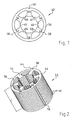
- FIG. 1 shows an exemplary embodiment of a single sheet 40 and FIG. 2 shows a laminated core (lamination stack) 42 produced therefrom for an internal rotor motor, the rotor 43 of which is indicated schematically in FIG. 4 and has four poles. Naturally, other numbers of poles are possible.
- the plate 40 has six salient stator poles 44, 46, 48, 50, 52 and 54 and a yoke 56. Outside, the plates 40 are provided with guide grooves 58 for their mounting.
- Grooves 61 to 66 are located between the stator poles.
- the groove 61 is located between the stator poles 44 and 46, etc., as shown in FIG.
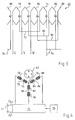
- Fig. 3 shows the arrangement of a three-phase stator winding 68 of known type in the grooves 61 to 66.
- a coil 70 which lies in the grooves 61 and 62.
- a cross-connection 72 to a coil 74, which is located at a distance of 360 ° el. (Based on the pole pitch of the rotor poles) of the coil 70 in the grooves 64 and 65.
- This coil 74 is in turn connected to a star point 76, that is, it is in the illustrated winding 68 to a star or Y-circuit.
- a triangular circuit would also be possible, as is known to the person skilled in the art.
- a terminal V connects to a coil 78 located in the slots 62 and 63, and from there goes a cross-connection 80 to a coil 82 disposed in the slots 65 and 66. This is also connected to the star point 76.
- connection W goes to a coil 84 located in the grooves 63 and 64, and from this a cross-connection 86 goes to a coil 88 located in the grooves 66 and 61 and also connected to the star point 76 ,
- Fig. 4 shows in the usual representation the six coils, their cross connectors 72, 80 and 86, and the star point 76.
- Each of the three strands U, V, W has two series-connected coils, which are interconnected via a transverse connection, such as described in Fig. 3
- the three strings U, V, W are connected to an output stage 71, which serves to supply the winding 68 with a three-phase current, preferably with sinusoidal currents, in order to achieve the most uniform possible torque.
- the energy comes from a DC link with a positive line 73 and a negative line 75, which supply their energy e.g. obtained from a battery 77, the voltage is usually at least 12 volts.
- a control unit 79 which provides the corresponding signals, as is known in the art.
- FIG. 5 to 11 show various views of a U-shaped insulating fitting 90 which surrounds one of the salient Statorpole (stator teeth) 44 to 54 on three sides after its assembly, as shown in Fig. 32 for the individual teeth 46 and 52 34, for the individual teeth 46 and 48.
- the fitting 90 has a short crosspiece 92, on which two longer legs 94, 96 are arranged, which are provided on their sides facing away from each other with insulating guide grooves 98. As shown in Fig. 2 and 6, the length L of the legs 94, 96 corresponds substantially to the length L (Fig. 2) of the laminated core 42.
- This fitting 90 may optionally be sprayed as an injection molded part directly to the corresponding stator tooth, which simplifies the production.
- FIGS. 12 to 14 show a U-shaped sheet metal part 100, which forms part of a coil of the stator winding 68 and is used to connect the phase U (or V, or W).
- it has a connection part 102 with three holes 104, of which 31 is one for connecting a cross connector 106, which is shown in FIGS. 27 to 29 shown in FIG. 31.
- the cross connectors 106 for the three phases U, V, W are largely, but not completely, identical.
- Such a transverse connector is shown in FIGS. 27 to 29 . They each have a peripheral portion 108, the mech over about 140 °. extends. This passes in Fig. 28 at the left end in an inwardly projecting portion 110, on which a projection 112 is provided, which is inserted in the assembly in one of the three holes 104 ( Figures 12 and 13) and electrically connected thereto , eg by welding, soldering, crimping or the like
- the cross-connector 106 has an inwardly projecting portion 114 which is bent at a location 116 and is therefore displaced parallel to the portion 108 by a distance D (FIG. 27).
- a recess 118 for connection to a winding element shown in FIGS. 18 to 20.
- the U-shaped sheet metal part 100 has, as shown in FIGS. 12 to 14, a roof-like profile. It has at the base of the U a short section 122 integrally formed with two longer legs 124, 126.
- the connecting part 102 is provided at the free end of the leg 126.
- At the free end of the leg 124 is a projection 128th
- Fig. 33 shows that there is the sheet metal part 100 in the fitting 90 in the uppermost guide recess 98, and that the projection 128 is electrically connected to a bow-shaped connecting part 130 having a recess 132 which surrounds this projection 128 and in this state is welded with him.
- the length of the sheet metal part 100 is shown in Fig. 13, where a length L 'for comparison is registered.
- the length L ' corresponds to the length L of the laminated core 42 plus the thickness of the part 92.
- the legs 124, 126 thus protrude only slightly out of the laminated core 142 so that the overall length of the stator 42 after its completion is as short as possible.
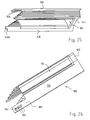
- Figs. 15 to 17 show a stamped and bent sheet metal part 134 which, like the other sheet metal parts, is made of copper or a copper alloy.
- Fig. 33 it is the third sheet metal part from below. It has at the base of the U a short connecting part 136, which is integral with two straight legs 138, 140, both of which are provided at their free ends with connecting elements 138A, 140A.
- the length L ' (according to the above definition) is entered in FIG. 16 for comparison. It can be seen that the legs 138, 140 continue to protrude from the laminated core 42, cf. Fig. 21.
- Figs. 18 to 20 show a punched and bent sheet metal part 142, which forms the lowermost turn in Fig. 33. It has at the base of the U a short connecting part 144, which is integrally formed with two straight legs 146, 148 which are provided at their free ends with connecting elements 146A, 148A.
- the length L ' (according to the above definition) is entered in FIG. 19 for comparison. It can be seen that the legs 146, 148 protrude farthest out of the laminated core 42, and from Fig. 33 it can be seen that these legs 146, 148 have the smallest width, because the width in Fig. 33 decreases from top to bottom. The reason is that according to FIGS.
- the width of the grooves 61 to 66 decreases from outside to inside, which is why the width of the legs 146, 148 must be adjusted accordingly, cf.
- the legs of the winding elements each extend almost to the middle of a groove in order to achieve a high copper fill factor.
- the leg 126 is wider and forms an exception to this rule, and therefore the leg opposite it of the adjacent coil is correspondingly narrower.
- Fig. 21 shows how the winding elements 100, 134, 142 are inserted into a molding 90. Between the winding elements 100 and 134 there are still two winding elements 150, 152 which have the same basic shape as the winding element 134, but somewhat shorter and wider than this. Also located between the winding elements 134 and 142 is a winding element 154, which has the same basic shape as the winding element 134, but slightly longer and slightly narrower than this. The winding elements 150, 152, 154 are not shown separately for this reason. The decrease in width is clear from Fig. 33 and, as explained, serves to achieve a good copper fill factor. The shape of the connecting elements at the ends of the legs or rods is shown in FIGS. 24, 25, 26 and 33.
- FIGS. 21 to 26 show, from various angles, a molded piece 90 filled with winding elements. If the shaped pieces 90 are manufactured separately, they are filled with the winding elements before they are mounted in the laminated core 42, cf. Fig. 30, where the left is shown and symbolized by a line 160. Subsequently, the filled fittings 90 are inserted into the laminated core 42. Alternatively, the fittings 90 can be made by injection molding directly in the laminated core 42, and in this case they are fitted in the laminated core 42 with the winding elements.
- the connectors 130 are attached to the winding elements, which is symbolized by a dashed line 162. Thereafter, the cross connectors 72, 80, 86 are mounted, symbolized by a line 164, and finally the assembly of the connector 76 for the star point, symbolized by a line 166, follows.
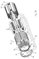
- FIG. 31 This results in a perspective view of the strand U the image shown in FIG. 31 and 32.
- Fig. 31 below - the still unfinished - coil 70 (see Fig. 4) with its port U shown.
- the transverse connector 72 With its innermost winding element 142 and its connection 148A, the transverse connector 72, as shown in FIGS. 27 to 29, is electrically connected to its recess 118.
- the dimension D shown in FIG. 27 is slightly larger in FIG. 31).
- the cross connector 72 leads as shown in FIGS. 31 and 32 to the coil 74 and there to the lowest hole 104 of the winding element 100, which is shown in FIGS. 12 to 14.
- the terminal 112 of the cross connector 72 projects into this hole 104 and is electrically good with him conductively connected.
- the innermost winding element 142 of the coil 74 is electrically conductively connected with its connection 148 to the star point conductor 76, whose shape is clearly evident from FIGS. 31 and 32. It is a stamped part made of copper sheet.
- Fig. 32 shows for better orientation and the position of the stator poles 44 to 54 and the grooves 61 to 66, as shown in Figs. 1 to 3. Further, in Figs. 31 and 32, the position of the cross connectors 80 and 86 are shown, although they have no function for the illustrated strand U and therefore float only freely in the room.
- Fig. 32 and the rotor 43 is indicated. This has four magnets 170, 172, 174, 176, whose polarity is indicated in the usual way with N and S and which are embedded in recesses of a laminated core 178 (embedded magnets).
- the rotor 43 is separated from the laminated core 42 by an air gap 180.
- FIG. 33 shows how the terminal 128 of the winding part 100 (in the radially outermost layer) is connected to a terminal 182 of the winding part 150 via the yoke-like connection part 130.
- the bracket 130 on the left has a recess 132, which is electrically conductively connected to the connection 128, and on the right has a recess 184, which is electrically conductively connected to the connection 182.
- the current thus flows in FIG. 33 from the terminal 102 through the winding element 100 to the terminal 128, from there via the yoke 130 to the terminal 182 of the winding element 150, then through this to its terminal 186, then from this terminal via a connecting link only symbolically indicated 188 to a terminal 190 of the winding element 152, then through this to its terminal 192nd
- connection bar 194 only symbolically indicated to the terminal 140A of the winding element 134, then through this to its terminal 138A, and from this via a connecting bar 196 only symbolically indicated to a terminal 198 of the winding element 154. Then flows Current through the element 154 to its terminal 200 and from there via a symbolically indicated connecting bracket 202 to the terminal 146A of the winding element 142, and through this to its terminal 148A, see. Fig. 18.
- the current either flows through a cross connector (see Figures 27 to 29) to the next coil of this string, or star point 76.
- Figs. 31 to 33 show only the lowermost connection arms 130 of the coils 70 and 74 in order to keep the drawing clear.
- the procedure is such that, after the assembly of the shaped pieces 90 with the winding elements (see Figures 21 to 26), the lowermost connecting bars 130 for all six coils 70, 74, 78, 82, 84, 88 are the first attaches the respective Windungs instituten and electrically good conductively connects with these. It is therefore preferable to process the connecting elements of a plane at the same time.
- the straps 188 ( Figures 33-36) of the next layer are then attached and electrically conductively connected, then sequentially the straps 194, 196 and 202 so that the individual coils are continuously conductive.
- the individual transverse connectors are mounted, beginning with the lowermost cross connector 72, the assembly of which has already been described in FIGS. 30 and 31, then the cross connector 86, and lastly the cross connector 80.
- the three holes 104 (FIG. 12) in the sheet metal part 100 allow connection to a cross connector regardless of which plane it is in.
- the wound stator lamination stack 42 then has its finished shape as shown in Figs. 34-36, and it is installed in a corresponding housing (not shown) which hermetically encloses the stator lamination stack, and the rotor 34 is placed in (not shown) bearings of this housing stored in the usual way.
- the electrical connections described can be carried out with low resistance, so that the stator winding has a low internal resistance because of the average cross-section of the electrical conductors and a strong one even at low voltages of the battery 77 (or another voltage source, eg a fuel cell) Can generate torque.
- the housing (not shown) is preferably hermetically sealed to the outside to prevent the ingress of foreign bodies which could cause a short circuit.
- the winding elements can be cooled by an oil circuit to achieve higher engine power.
Applications Claiming Priority (1)
| Application Number | Priority Date | Filing Date | Title |
|---|---|---|---|
| DE102004046544A DE102004046544A1 (de) | 2004-09-20 | 2004-09-20 | Motor, insbesondere für Niederspannung |
Publications (2)
| Publication Number | Publication Date |
|---|---|
| EP1638188A1 true EP1638188A1 (fr) | 2006-03-22 |
| EP1638188B1 EP1638188B1 (fr) | 2007-05-02 |
Family
ID=34937816
Family Applications (1)
| Application Number | Title | Priority Date | Filing Date |
|---|---|---|---|
| EP05014930A Not-in-force EP1638188B1 (fr) | 2004-09-20 | 2005-07-09 | Moteur, en particulier pour basse tension |
Country Status (3)
| Country | Link |
|---|---|
| EP (1) | EP1638188B1 (fr) |
| AT (1) | ATE361575T1 (fr) |
| DE (2) | DE102004046544A1 (fr) |
Cited By (4)
| Publication number | Priority date | Publication date | Assignee | Title |
|---|---|---|---|---|
| EP1947755A1 (fr) * | 2007-01-19 | 2008-07-23 | ENGEL Elektroantriebe GmbH | Stator d'une machine électrique |
| EP1988619A1 (fr) * | 2007-04-25 | 2008-11-05 | Hitachi, Ltd. | Machine électrique rotative, unité de distribution de puissance et procédé pour assembler la machine électrique rotative |
| CN106471717A (zh) * | 2014-06-09 | 2017-03-01 | 日产自动车株式会社 | 扁平线定子线圈的制造方法 |
| CN108141084A (zh) * | 2015-11-09 | 2018-06-08 | 大陆汽车有限公司 | 具有用于绕组连接的电路板组件的电动机器和相关制造方法 |
Families Citing this family (4)
| Publication number | Priority date | Publication date | Assignee | Title |
|---|---|---|---|---|
| DE102009034660A1 (de) | 2008-08-01 | 2010-02-04 | Ebm-Papst St. Georgen Gmbh & Co. Kg | Elektrische Maschine, insbesondere elektronisch kommutierter Motor |
| DE102011088658A1 (de) * | 2011-12-15 | 2013-06-20 | Zf Friedrichshafen Ag | Stator einer elektrischen Maschine mit Spannungsisoliermitteln |
| DE102015208414A1 (de) | 2015-05-06 | 2016-11-10 | Robert Bosch Gmbh | Wicklungszahn einer elektrischen Maschine |
| DE102021127073A1 (de) | 2021-10-19 | 2023-04-20 | Bayerische Motoren Werke Aktiengesellschaft | Rotor mit Querverbindern, elektrische Maschine sowie Verfahren zum Herstellen eines Rotors |
Citations (7)
| Publication number | Priority date | Publication date | Assignee | Title |
|---|---|---|---|---|
| GB622032A (en) * | 1947-03-04 | 1949-04-26 | British Thomson Houston Co Ltd | Improvements relating to the windings of dynamo-electric machines |
| DE1018528B (de) * | 1955-12-22 | 1957-10-31 | Siemens Ag | Magnetpol mit flachkant gewickelter Polspule, insbesondere Wendepol |
| US3333131A (en) * | 1964-12-01 | 1967-07-25 | Westinghouse Electric Corp | Commutating pole assembly for a dynamoelectric machine |
| US3543067A (en) * | 1968-03-25 | 1970-11-24 | Westinghouse Electric Corp | Commutating field coil insulation and support structure |
| US20010010442A1 (en) * | 2000-01-31 | 2001-08-02 | Hitachi, Ltd. And Hitachi Car Engineering Co., Tld. | Stator of rotating electric machine |
| JP2002044894A (ja) * | 2000-07-26 | 2002-02-08 | Aisin Seiki Co Ltd | 回転電機の絶縁部材 |
| EP1207613A2 (fr) * | 2000-11-15 | 2002-05-22 | Hitachi, Ltd. | Assemblage de bobines pour un stator |
-
2004
- 2004-09-20 DE DE102004046544A patent/DE102004046544A1/de not_active Withdrawn
-
2005
- 2005-07-09 AT AT05014930T patent/ATE361575T1/de not_active IP Right Cessation
- 2005-07-09 DE DE502005000654T patent/DE502005000654D1/de active Active
- 2005-07-09 EP EP05014930A patent/EP1638188B1/fr not_active Not-in-force
Patent Citations (7)
| Publication number | Priority date | Publication date | Assignee | Title |
|---|---|---|---|---|
| GB622032A (en) * | 1947-03-04 | 1949-04-26 | British Thomson Houston Co Ltd | Improvements relating to the windings of dynamo-electric machines |
| DE1018528B (de) * | 1955-12-22 | 1957-10-31 | Siemens Ag | Magnetpol mit flachkant gewickelter Polspule, insbesondere Wendepol |
| US3333131A (en) * | 1964-12-01 | 1967-07-25 | Westinghouse Electric Corp | Commutating pole assembly for a dynamoelectric machine |
| US3543067A (en) * | 1968-03-25 | 1970-11-24 | Westinghouse Electric Corp | Commutating field coil insulation and support structure |
| US20010010442A1 (en) * | 2000-01-31 | 2001-08-02 | Hitachi, Ltd. And Hitachi Car Engineering Co., Tld. | Stator of rotating electric machine |
| JP2002044894A (ja) * | 2000-07-26 | 2002-02-08 | Aisin Seiki Co Ltd | 回転電機の絶縁部材 |
| EP1207613A2 (fr) * | 2000-11-15 | 2002-05-22 | Hitachi, Ltd. | Assemblage de bobines pour un stator |
Non-Patent Citations (1)
| Title |
|---|
| PATENT ABSTRACTS OF JAPAN vol. 2002, no. 06 4 June 2002 (2002-06-04) * |
Cited By (10)
| Publication number | Priority date | Publication date | Assignee | Title |
|---|---|---|---|---|
| EP1947755A1 (fr) * | 2007-01-19 | 2008-07-23 | ENGEL Elektroantriebe GmbH | Stator d'une machine électrique |
| EP1988619A1 (fr) * | 2007-04-25 | 2008-11-05 | Hitachi, Ltd. | Machine électrique rotative, unité de distribution de puissance et procédé pour assembler la machine électrique rotative |
| US7952245B2 (en) | 2007-04-25 | 2011-05-31 | Hitachi, Ltd. | Power distribution unit for rotary electric machine with linear conductor connecting ring having terminal section with axially extending hole for connecting stator coil, and method for assembling rotary electric machine |
| CN106471717A (zh) * | 2014-06-09 | 2017-03-01 | 日产自动车株式会社 | 扁平线定子线圈的制造方法 |
| EP3154159A4 (fr) * | 2014-06-09 | 2017-04-12 | Nissan Motor Co., Ltd | Procédé de fabrication d'une bobine de stator à fils plats |
| US9825513B2 (en) | 2014-06-09 | 2017-11-21 | Nissan Motor Co., Ltd. | Rectangular wire stator coil manufacturing method |
| CN106471717B (zh) * | 2014-06-09 | 2018-12-07 | 日产自动车株式会社 | 扁平线定子线圈的制造方法 |
| CN108141084A (zh) * | 2015-11-09 | 2018-06-08 | 大陆汽车有限公司 | 具有用于绕组连接的电路板组件的电动机器和相关制造方法 |
| US20180262072A1 (en) * | 2015-11-09 | 2018-09-13 | Continental Automotive Gmbh | Electrical machine having a printed circuit board arrangement for winding interconnection and associated production method |
| US10897170B2 (en) * | 2015-11-09 | 2021-01-19 | Vitesco Technologies GmbH | Electrical machine having a printed circuit board arrangement for winding interconnection and associated production method |
Also Published As
| Publication number | Publication date |
|---|---|
| DE102004046544A1 (de) | 2006-04-27 |
| DE502005000654D1 (de) | 2007-06-14 |
| ATE361575T1 (de) | 2007-05-15 |
| EP1638188B1 (fr) | 2007-05-02 |
Similar Documents
| Publication | Publication Date | Title |
|---|---|---|
| EP1526628B1 (fr) | Unité de connexion d'un stator de moteur électrique | |
| EP2139094B1 (fr) | Stator et arrangement de connection d'une machine électrique | |
| EP1638188B1 (fr) | Moteur, en particulier pour basse tension | |
| EP1810388B1 (fr) | Moteur electrique | |
| EP1505711B1 (fr) | Moteur électrique | |
| EP3298679A1 (fr) | Stator d'une machine electrique et procédé de production d'un tel stator | |
| EP3078099B1 (fr) | Stator pour moteur à courant continu à commutation électronique | |
| WO2010066491A2 (fr) | Moteur électrique, en particulier servomoteur ou moteur d'entraînement dans des véhicules automobiles | |
| DE202009000415U1 (de) | Elektronisch kommutierter Motor | |
| DE112013003484T5 (de) | Integrierter Phasenanschlussisolator mit einzelnem Phasentrenner | |
| DE102014201637A1 (de) | Stromschiene für einen Stator, Stator, Elektromotor und Verfahren zum Herstellen eines Stators | |
| DE102015211786A1 (de) | Stator | |
| WO2016180588A1 (fr) | Stator pour une machine électrique doté d'un dispositif d'interconnexion encapsulé et machine électrique équipée d'un tel stator | |
| WO2003063322A2 (fr) | Ensemble stator | |
| DE102017101073A1 (de) | Statorpaket und Verfahren zum Herstellen eines Statorpakets | |
| DE102006019586A1 (de) | Asynchron-Motor mit innerem Rotor | |
| DE102019004591A1 (de) | Elektromotor mit einer Verschaltungseinheit und Verfahren zur Herstellung eines Elektromotors mit einer Verschaltungseinheit | |
| WO2010066493A2 (fr) | Stator dans un moteur électrique | |
| DE102006051458A1 (de) | Motor, Kommutator, Kurzschlusselement und Verfahren zur Herstellung des Kommutators | |
| WO2007014570A1 (fr) | Moteur electrique et procede de production correspondant | |
| DE202005014302U1 (de) | Motor, insbesondere für Niederspannung | |
| WO2016202549A1 (fr) | Bobine préformée, structure de bobinages et stator d'un générateur d'une éolienne ainsi que procédé de fabrication d'un stator | |
| DE3817912A1 (de) | Stator einer in kraftfahrzeugen angeordneten wechselstrommaschine | |
| EP3824529A1 (fr) | Moteur électrique comprenant une unité de câblage et procédé de réalisation d'un moteur électrique comprenant une unité de câblage | |
| DE102019004589A1 (de) | Elektromotor mit einer Verschaltungseinheit und Verfahren zur Herstellung eines Elektromotors mit einer Verschaltungseinheit |
Legal Events
| Date | Code | Title | Description |
|---|---|---|---|
| PUAI | Public reference made under article 153(3) epc to a published international application that has entered the european phase |
Free format text: ORIGINAL CODE: 0009012 |
|
| 17P | Request for examination filed |
Effective date: 20050920 |
|
| AK | Designated contracting states |
Kind code of ref document: A1 Designated state(s): AT BE BG CH CY CZ DE DK EE ES FI FR GB GR HU IE IS IT LI LT LU LV MC NL PL PT RO SE SI SK TR |
|
| AX | Request for extension of the european patent |
Extension state: AL BA HR MK YU |
|
| AKX | Designation fees paid |
Designated state(s): AT BE BG CH CY CZ DE DK EE ES FI FR GB GR HU IE IS IT LI LT LU LV MC NL PL PT RO SE SI SK TR |
|
| GRAP | Despatch of communication of intention to grant a patent |
Free format text: ORIGINAL CODE: EPIDOSNIGR1 |
|
| GRAS | Grant fee paid |
Free format text: ORIGINAL CODE: EPIDOSNIGR3 |
|
| GRAA | (expected) grant |
Free format text: ORIGINAL CODE: 0009210 |
|
| AK | Designated contracting states |
Kind code of ref document: B1 Designated state(s): AT BE BG CH CY CZ DE DK EE ES FI FR GB GR HU IE IS IT LI LT LU LV MC NL PL PT RO SE SI SK TR |
|
| PG25 | Lapsed in a contracting state [announced via postgrant information from national office to epo] |
Ref country code: FI Free format text: LAPSE BECAUSE OF FAILURE TO SUBMIT A TRANSLATION OF THE DESCRIPTION OR TO PAY THE FEE WITHIN THE PRESCRIBED TIME-LIMIT Effective date: 20070502 |
|
| REG | Reference to a national code |
Ref country code: GB Ref legal event code: FG4D Free format text: NOT ENGLISH |
|
| REG | Reference to a national code |
Ref country code: CH Ref legal event code: EP |
|
| REG | Reference to a national code |
Ref country code: IE Ref legal event code: FG4D Free format text: LANGUAGE OF EP DOCUMENT: GERMAN |
|
| REF | Corresponds to: |
Ref document number: 502005000654 Country of ref document: DE Date of ref document: 20070614 Kind code of ref document: P |
|
| GBT | Gb: translation of ep patent filed (gb section 77(6)(a)/1977) |
Effective date: 20070605 |
|
| REG | Reference to a national code |
Ref country code: SE Ref legal event code: TRGR |
|
| PG25 | Lapsed in a contracting state [announced via postgrant information from national office to epo] |
Ref country code: ES Free format text: LAPSE BECAUSE OF FAILURE TO SUBMIT A TRANSLATION OF THE DESCRIPTION OR TO PAY THE FEE WITHIN THE PRESCRIBED TIME-LIMIT Effective date: 20070813 |
|
| PG25 | Lapsed in a contracting state [announced via postgrant information from national office to epo] |
Ref country code: IS Free format text: LAPSE BECAUSE OF FAILURE TO SUBMIT A TRANSLATION OF THE DESCRIPTION OR TO PAY THE FEE WITHIN THE PRESCRIBED TIME-LIMIT Effective date: 20070902 |
|
| NLV1 | Nl: lapsed or annulled due to failure to fulfill the requirements of art. 29p and 29m of the patents act | ||
| ET | Fr: translation filed | ||
| PG25 | Lapsed in a contracting state [announced via postgrant information from national office to epo] |
Ref country code: PL Free format text: LAPSE BECAUSE OF FAILURE TO SUBMIT A TRANSLATION OF THE DESCRIPTION OR TO PAY THE FEE WITHIN THE PRESCRIBED TIME-LIMIT Effective date: 20070502 |
|
| REG | Reference to a national code |
Ref country code: IE Ref legal event code: FD4D |
|
| BERE | Be: lapsed |
Owner name: EBM-PAPST ST. GEORGEN G.M.B.H. & CO. KG Effective date: 20070731 |
|
| PG25 | Lapsed in a contracting state [announced via postgrant information from national office to epo] |
Ref country code: PT Free format text: LAPSE BECAUSE OF FAILURE TO SUBMIT A TRANSLATION OF THE DESCRIPTION OR TO PAY THE FEE WITHIN THE PRESCRIBED TIME-LIMIT Effective date: 20071002 Ref country code: SI Free format text: LAPSE BECAUSE OF FAILURE TO SUBMIT A TRANSLATION OF THE DESCRIPTION OR TO PAY THE FEE WITHIN THE PRESCRIBED TIME-LIMIT Effective date: 20070502 Ref country code: NL Free format text: LAPSE BECAUSE OF FAILURE TO SUBMIT A TRANSLATION OF THE DESCRIPTION OR TO PAY THE FEE WITHIN THE PRESCRIBED TIME-LIMIT Effective date: 20070502 Ref country code: CZ Free format text: LAPSE BECAUSE OF FAILURE TO SUBMIT A TRANSLATION OF THE DESCRIPTION OR TO PAY THE FEE WITHIN THE PRESCRIBED TIME-LIMIT Effective date: 20070502 Ref country code: DK Free format text: LAPSE BECAUSE OF FAILURE TO SUBMIT A TRANSLATION OF THE DESCRIPTION OR TO PAY THE FEE WITHIN THE PRESCRIBED TIME-LIMIT Effective date: 20070502 Ref country code: IE Free format text: LAPSE BECAUSE OF FAILURE TO SUBMIT A TRANSLATION OF THE DESCRIPTION OR TO PAY THE FEE WITHIN THE PRESCRIBED TIME-LIMIT Effective date: 20070502 Ref country code: BG Free format text: LAPSE BECAUSE OF FAILURE TO SUBMIT A TRANSLATION OF THE DESCRIPTION OR TO PAY THE FEE WITHIN THE PRESCRIBED TIME-LIMIT Effective date: 20070802 |
|
| PG25 | Lapsed in a contracting state [announced via postgrant information from national office to epo] |
Ref country code: SK Free format text: LAPSE BECAUSE OF FAILURE TO SUBMIT A TRANSLATION OF THE DESCRIPTION OR TO PAY THE FEE WITHIN THE PRESCRIBED TIME-LIMIT Effective date: 20070502 Ref country code: LV Free format text: LAPSE BECAUSE OF FAILURE TO SUBMIT A TRANSLATION OF THE DESCRIPTION OR TO PAY THE FEE WITHIN THE PRESCRIBED TIME-LIMIT Effective date: 20070502 Ref country code: LT Free format text: LAPSE BECAUSE OF FAILURE TO SUBMIT A TRANSLATION OF THE DESCRIPTION OR TO PAY THE FEE WITHIN THE PRESCRIBED TIME-LIMIT Effective date: 20070502 |
|
| PLBE | No opposition filed within time limit |
Free format text: ORIGINAL CODE: 0009261 |
|
| STAA | Information on the status of an ep patent application or granted ep patent |
Free format text: STATUS: NO OPPOSITION FILED WITHIN TIME LIMIT |
|
| 26N | No opposition filed |
Effective date: 20080205 |
|
| PG25 | Lapsed in a contracting state [announced via postgrant information from national office to epo] |
Ref country code: MC Free format text: LAPSE BECAUSE OF NON-PAYMENT OF DUE FEES Effective date: 20070731 Ref country code: GR Free format text: LAPSE BECAUSE OF FAILURE TO SUBMIT A TRANSLATION OF THE DESCRIPTION OR TO PAY THE FEE WITHIN THE PRESCRIBED TIME-LIMIT Effective date: 20070803 |
|
| PG25 | Lapsed in a contracting state [announced via postgrant information from national office to epo] |
Ref country code: RO Free format text: LAPSE BECAUSE OF FAILURE TO SUBMIT A TRANSLATION OF THE DESCRIPTION OR TO PAY THE FEE WITHIN THE PRESCRIBED TIME-LIMIT Effective date: 20070502 |
|
| PG25 | Lapsed in a contracting state [announced via postgrant information from national office to epo] |
Ref country code: BE Free format text: LAPSE BECAUSE OF NON-PAYMENT OF DUE FEES Effective date: 20070731 |
|
| PG25 | Lapsed in a contracting state [announced via postgrant information from national office to epo] |
Ref country code: AT Free format text: LAPSE BECAUSE OF NON-PAYMENT OF DUE FEES Effective date: 20070709 |
|
| PG25 | Lapsed in a contracting state [announced via postgrant information from national office to epo] |
Ref country code: EE Free format text: LAPSE BECAUSE OF FAILURE TO SUBMIT A TRANSLATION OF THE DESCRIPTION OR TO PAY THE FEE WITHIN THE PRESCRIBED TIME-LIMIT Effective date: 20070502 |
|
| PG25 | Lapsed in a contracting state [announced via postgrant information from national office to epo] |
Ref country code: CY Free format text: LAPSE BECAUSE OF FAILURE TO SUBMIT A TRANSLATION OF THE DESCRIPTION OR TO PAY THE FEE WITHIN THE PRESCRIBED TIME-LIMIT Effective date: 20070502 |
|
| PG25 | Lapsed in a contracting state [announced via postgrant information from national office to epo] |
Ref country code: LU Free format text: LAPSE BECAUSE OF NON-PAYMENT OF DUE FEES Effective date: 20070709 |
|
| PG25 | Lapsed in a contracting state [announced via postgrant information from national office to epo] |
Ref country code: HU Free format text: LAPSE BECAUSE OF FAILURE TO SUBMIT A TRANSLATION OF THE DESCRIPTION OR TO PAY THE FEE WITHIN THE PRESCRIBED TIME-LIMIT Effective date: 20071103 Ref country code: TR Free format text: LAPSE BECAUSE OF FAILURE TO SUBMIT A TRANSLATION OF THE DESCRIPTION OR TO PAY THE FEE WITHIN THE PRESCRIBED TIME-LIMIT Effective date: 20070502 |
|
| REG | Reference to a national code |
Ref country code: CH Ref legal event code: PL |
|
| PG25 | Lapsed in a contracting state [announced via postgrant information from national office to epo] |
Ref country code: CH Free format text: LAPSE BECAUSE OF NON-PAYMENT OF DUE FEES Effective date: 20090731 Ref country code: LI Free format text: LAPSE BECAUSE OF NON-PAYMENT OF DUE FEES Effective date: 20090731 |
|
| REG | Reference to a national code |
Ref country code: FR Ref legal event code: PLFP Year of fee payment: 11 |
|
| REG | Reference to a national code |
Ref country code: DE Ref legal event code: R084 Ref document number: 502005000654 Country of ref document: DE |
|
| PGFP | Annual fee paid to national office [announced via postgrant information from national office to epo] |
Ref country code: IT Payment date: 20150422 Year of fee payment: 11 Ref country code: FR Payment date: 20150610 Year of fee payment: 11 |
|
| PGFP | Annual fee paid to national office [announced via postgrant information from national office to epo] |
Ref country code: GB Payment date: 20150805 Year of fee payment: 11 |
|
| PGFP | Annual fee paid to national office [announced via postgrant information from national office to epo] |
Ref country code: SE Payment date: 20150720 Year of fee payment: 11 |
|
| REG | Reference to a national code |
Ref country code: SE Ref legal event code: EUG |
|
| GBPC | Gb: european patent ceased through non-payment of renewal fee |
Effective date: 20160709 |
|
| PG25 | Lapsed in a contracting state [announced via postgrant information from national office to epo] |
Ref country code: SE Free format text: LAPSE BECAUSE OF NON-PAYMENT OF DUE FEES Effective date: 20160710 Ref country code: FR Free format text: LAPSE BECAUSE OF NON-PAYMENT OF DUE FEES Effective date: 20160801 |
|
| REG | Reference to a national code |
Ref country code: FR Ref legal event code: ST Effective date: 20170331 |
|
| PG25 | Lapsed in a contracting state [announced via postgrant information from national office to epo] |
Ref country code: GB Free format text: LAPSE BECAUSE OF NON-PAYMENT OF DUE FEES Effective date: 20160709 |
|
| PG25 | Lapsed in a contracting state [announced via postgrant information from national office to epo] |
Ref country code: IT Free format text: LAPSE BECAUSE OF NON-PAYMENT OF DUE FEES Effective date: 20160709 |
|
| REG | Reference to a national code |
Ref country code: DE Ref legal event code: R231 Ref document number: 502005000654 Country of ref document: DE |
|
| PG25 | Lapsed in a contracting state [announced via postgrant information from national office to epo] |
Ref country code: DE Free format text: LAPSE BECAUSE OF THE APPLICANT RENOUNCES Effective date: 20180818 |
|
| PGFP | Annual fee paid to national office [announced via postgrant information from national office to epo] |
Ref country code: DE Payment date: 20180703 Year of fee payment: 14 |