EP1638188A1 - Motor, especially for low voltage - Google Patents
Motor, especially for low voltage Download PDFInfo
- Publication number
- EP1638188A1 EP1638188A1 EP05014930A EP05014930A EP1638188A1 EP 1638188 A1 EP1638188 A1 EP 1638188A1 EP 05014930 A EP05014930 A EP 05014930A EP 05014930 A EP05014930 A EP 05014930A EP 1638188 A1 EP1638188 A1 EP 1638188A1
- Authority
- EP
- European Patent Office
- Prior art keywords
- winding
- elements
- motor according
- stator
- coils
- Prior art date
- Legal status (The legal status is an assumption and is not a legal conclusion. Google has not performed a legal analysis and makes no representation as to the accuracy of the status listed.)
- Granted
Links
Images


Classifications
-
- H—ELECTRICITY
- H02—GENERATION; CONVERSION OR DISTRIBUTION OF ELECTRIC POWER
- H02K—DYNAMO-ELECTRIC MACHINES
- H02K3/00—Details of windings
- H02K3/04—Windings characterised by the conductor shape, form or construction, e.g. with bar conductors
- H02K3/18—Windings for salient poles
-
- H—ELECTRICITY
- H02—GENERATION; CONVERSION OR DISTRIBUTION OF ELECTRIC POWER
- H02K—DYNAMO-ELECTRIC MACHINES
- H02K3/00—Details of windings
- H02K3/32—Windings characterised by the shape, form or construction of the insulation
- H02K3/325—Windings characterised by the shape, form or construction of the insulation for windings on salient poles, such as claw-shaped poles
-
- H—ELECTRICITY
- H02—GENERATION; CONVERSION OR DISTRIBUTION OF ELECTRIC POWER
- H02K—DYNAMO-ELECTRIC MACHINES
- H02K3/00—Details of windings
- H02K3/32—Windings characterised by the shape, form or construction of the insulation
- H02K3/34—Windings characterised by the shape, form or construction of the insulation between conductors or between conductor and core, e.g. slot insulation
- H02K3/345—Windings characterised by the shape, form or construction of the insulation between conductors or between conductor and core, e.g. slot insulation between conductor and core, e.g. slot insulation
-
- H—ELECTRICITY
- H02—GENERATION; CONVERSION OR DISTRIBUTION OF ELECTRIC POWER
- H02K—DYNAMO-ELECTRIC MACHINES
- H02K3/00—Details of windings
- H02K3/46—Fastening of windings on the stator or rotor structure
- H02K3/50—Fastening of winding heads, equalising connectors, or connections thereto
-
- H—ELECTRICITY
- H02—GENERATION; CONVERSION OR DISTRIBUTION OF ELECTRIC POWER
- H02K—DYNAMO-ELECTRIC MACHINES
- H02K3/00—Details of windings
- H02K3/46—Fastening of windings on the stator or rotor structure
- H02K3/52—Fastening salient pole windings or connections thereto
- H02K3/521—Fastening salient pole windings or connections thereto applicable to stators only
- H02K3/522—Fastening salient pole windings or connections thereto applicable to stators only for generally annular cores with salient poles
Landscapes
- Engineering & Computer Science (AREA)
- Power Engineering (AREA)
- Windings For Motors And Generators (AREA)
- Insulation, Fastening Of Motor, Generator Windings (AREA)
- Iron Core Of Rotating Electric Machines (AREA)
- Fixed Capacitors And Capacitor Manufacturing Machines (AREA)
Abstract
Description
Die Erfindung betrifft einen Motor, insbesondere für Niederspannung.The invention relates to a motor, in particular for low voltage.
Im Elektromotorenbau wird eine Motorwicklung üblicherweise mit lackisolierten Kupferdrähten hergestellt. Die Lackisolierung ist ein- oder mehrschichtig aufgetragen. Je nach Verwendung werden spezielle Lackqualitäten verwendet, z.B. für hohe Motortemperaturen. Eine solche Lackisolierung isoliert die aneinander liegenden Drähte einer Motorspule.In electric motor construction, a motor winding is usually made with enamel-insulated copper wires. The paint insulation is applied in one or more layers. Depending on the application, special paint qualities are used, e.g. for high engine temperatures. Such paint insulation isolates the adjacent wires of a motor coil.
Ferner wird bei überlappten Wicklungen (Drehstrommotoren) zwischen den Phasen der Wicklung eine sogenannte Phasenisolierung verwendet. Diese Wicklungen werden anschließend je nach den Erfordernissen zusätzlich mit Isolierlacken im Tauch- bzw. Träufelverfahren imprägniert. Die verwendeten Drahtdurchmesser liegen meist zwischen 0,1 und 1,5 mm.Furthermore, in the case of overlapped windings (three-phase motors), a so-called phase insulation is used between the phases of the winding. These windings are then additionally impregnated, depending on the requirements, with insulating lacquers in a dipping or dropping process. The wire diameters used are usually between 0.1 and 1.5 mm.
Zur Herstellung solcher Spulen gibt es verschiedene Wickelverfahren.There are various winding methods for producing such coils.
Z.B. können die Motorspulen auf Spulenkörper gewickelt werden. Bei Außenläufermotoren und Kollektormotoren verwendet man eine Flyerwickeltechnik. Bei Kurzschlussläufermotoren (Drehstrommotoren und Einphasenmotoren) verwendet man das Flyerwickeln und die Einziehtechnik. Bei Universalmotoren und bei der Einzelzahnwicklung bei elektronisch kommutierten Motoren (ECM) verwendet man die Nadelwickeltechnik.For example, The motor coils can be wound on bobbin. External rotor motors and collector motors use a flyer winding technology. In squirrel cage motors (three-phase motors and single-phase motors), flyer winding and retraction technology are used. For universal motors and single-tooth winding in electronically commutated motors (ECM), the needle winding technique is used.
Diese Wickelverfahren erreichen Kupferfüllfaktoren von 100 % bei Verwendung eines Spulenkörpers, von ca. 70 % bei Drehstrommotoren, und von ca. 35 % bei der Nadelwickeltechnik.These winding methods achieve copper fill factors of 100% when using a bobbin, of about 70% for three-phase motors, and about 35% for needle winding technology.
Es ist auch bekannt, in der Hochstromtechnik (Drehstromgeneratoren) - statt der bekannten Wickeltechnik - bei Windungszahlen von ein bis zehn Windungen pro Spule statt Wickeldrähten Kupferstäbe mit Bandagenlsolierungen zu verwenden, oder sogenannte Hairpins (haarnadelförmige Spulen) in Form von Lack isolierten Dickdrähten.It is also known in high current technology (three-phase generators) - instead of the known winding technology - to use coil rods with Bandagenlsolierungen with turns of one to ten turns per coil instead of winding wires, or so-called hairpins (hairpin-shaped coils) in the form of paint insulated thick wires.
Bei manchen Antriebsaufgaben steht nur eine Spannungsquelle mit niedriger Spannung zur Verfügung, z.B. auf Fahrzeugen, und deshalb muss dort die Statorwicklung einen niedrigen Innenwiderstand haben, wenn man ein ausreichend hohes Drehmoment anstrebt. Dies bedeutet, dass man pro Spule Windungszahlen von weniger als zehn Windungen hat, und dass diese Windungen große Querschnitte haben müssen. Dabei ist es wichtig, Kurzschlüsse zwischen den einzelnen Windungen zu vermeiden, wie sie durch Schwachstellen der Lackdrahtisolierung oder Isolationsschäden beim Wickelvorgang entstehen können.For some drive tasks, only one low voltage power source is available, e.g. on vehicles, and therefore there must have the stator winding has a low internal resistance, if one strives for a sufficiently high torque. This means that you have less than ten turns per coil, and that these turns must have large cross sections. It is important to avoid short circuits between the individual windings, as may occur due to weak points in the enameled wire insulation or insulation damage during the winding process.
Es ist deshalb eine Aufgabe der Erfindung, einen neuen Motor bereit zu stellen, welcher sich insbesondere für Betrieb mit niedrigen Spannungen eignet.It is therefore an object of the invention to provide a new motor which is particularly suitable for low voltage operation.
Diese Aufgabe wird erfindungsgemäß gelöst durch einen Motor gemäß Anspruch 1. Hierbei haben die einzelnen Spulen U-förmige Wicklungselemente, deren Leiterquerschnitt zumindest überwiegend von der Kreisform abweicht. An einem Polkern ist ein Formstück vorgesehen, das auf seiner Außenseite mit isolierenden Führungsausnehmungen für die genannten Wicklungselemente versehen ist. Dieses Formstück hat die Aufgabe, die Wicklungselemente gegen den zugeordneten Polkern (Zahn des Statorblechpakets) zu isolieren, und diese Wicklungselemente in einem gesicherten, isolierten Abstand voneinander zu halten. Man kann dieses Formstück einzeln oder im Verbund auf die Statorzähne aufschieben. Auch kann es z.B. im Spritzguss oder in sonstiger geeigneter Weise auf den betreffenden Zahn aufgebracht werden. Es hat folgende Funktionen:
- a) Isolation Windung gegen Windung, also die sogenannte Lagenisolation.
- b) Isolation Windung gegen Statoreisen, also die sogenannte Betriebsisolation.
- a) Isolation turn against turn, so the so-called layer insulation.
- b) Isolation Winding against stator iron, ie the so-called operational insulation.
Die Erfindung ermöglicht also bevorzugt das Einbringen von Spulen mit Windungszahlen von kleiner als zehn Windungen und mit hohen Windungsquerschnitten. Sie ermöglicht ferner Nutfüllfaktoren von >50 % für Einzelzahnwicklungen, und sie ermöglicht die Vermeidung von Windungsschlüssen, wie sie sonst durch Schwachstellen der Lackdrahtisolierung bzw. durch Beschädigungen dieser Isolation bei der Herstellung solcher Spulen auftreten können.The invention thus preferably allows the introduction of coils with Winding numbers of less than ten windings and with high winding cross sections. It also enables groove fill factors of> 50% for single-tooth windings, and it prevents the formation of windings, which can otherwise occur as a result of weak points in the enameled wire insulation or damage to this insulation in the manufacture of such coils.
Weitere Einzelheiten und vorteilhafte Weiterbildungen der Erfindung ergeben sich aus dem im folgenden beschriebenen und in der Zeichnung dargestellten, in keiner Weise als Einschränkung der Erfindung zu verstehenden Ausführungsbeispiel, sowie aus den Unteransprüchen. Es zeigt:
- Fig. 1
- ein Statorblech, wie es bei der Erfindung verwendet werden kann,
- Fig. 2
- ein Statorblechpaket, welches aus Statorblechen gemäß Fig. 1 hergestellt ist.
- Fig. 3
- eine Darstellung einer Drehstromwicklung für das Statorblechpaket der Fig. 2,
- Fig. 4
- eine Darstellung der Statorwicklung gemäß Fig. 3 in üblicher Darstellung und in sogenannter Sternschaltung, zusammen mit Bauteilen für die elektronische Kommutierung,
- Fig. 5
- eine Draufsicht auf einen in Fig. 6 dargestellten Isolierkörper, gesehen in Richtung des Pfeiles V der Fig. 6,
- Fig. 6
- eine Darstellung des Isolierkörpers der Fig. 5, gesehen in Richtung des Pfeiles VI der Fig. 5,
- Fig. 7
- eine Draufsicht auf den Isolierkörper der Fig. 6, gesehen in Richtung des Pfeiles VII der Fig. 6,
- Fig. 8 bis Fig. 11
- raumbildliche Darstellungen des Isolierkörpers der Fig. 5 bis 7, gesehen aus verschiedenen Richtungen,
- Fig. 12
- eine raumbildliche Darstellung eines ersten U-förmigen
Wicklungselements 100, welches einAnschlussglied 102 zum Anschluss an eine der Phasen U, V oder W hat, - Fig. 13
- eine Draufsicht von oben auf das
Wicklungselement 100 der Fig. 12, gesehen in Richtung des Pfeiles XIII der Fig. 12, - Fig. 14
- eine Draufsicht auf das
Wicklungselement 100 der Fig. 12 und 13, gesehen in Richtung des Pfeiles XIV der Fig. 13, - Fig. 15
- eine raumbildliche Darstellung eines U-förmigen
Wicklungselements 134, welches einen Teil einer einzelnen Windung bildet, - Fig. 16
- eine Draufsicht, gesehen in Richtung des Pfeiles XVI der Fig. 15,
- Fig. 17
- eine Draufsicht, gesehen in Richtung des Pfeiles XVII der Fig. 16,
- Fig. 18
- eine Draufsicht von unten auf ein U-förmiges
Wicklungselement 142, welches zum Anschluss eines Wicklungsstrangs an denSternpunkt 76 des Motors dient, - Fig. 19
- eine Draufsicht, gesehen in Richtung des Pfeiles XIX der Fig. 18,
- Fig. 20
- eine Draufsicht, gesehen in Richtung des Pfeiles XX der Fig. 19,
- Fig. 21
- eine Darstellung einer teilweise fertig gestellten Spule mit insgesamt fünf Windungen, welche auf einem Isolierkörper nach den Fig. 5 bis 11 angeordnet sind, in raumbildlicher Darstellung,
- Fig. 22
- eine Draufsicht auf die Anordnung der Fig. 21, gesehen in Richtung des Pfeiles XXII der Fig. 23,
- Fig. 23
- eine Draufsicht, gesehen in Richtung des Pfeiles XXIII der Fig. 22,
- Fig. 24
- eine Draufsicht, gesehen in Richtung des Pfeiles XXIV der Fig. 23,
- Fig. 25
- eine raumbildliche Darstellung analog Fig. 21, aber gesehen aus einem anderen Blickwinkel,
- Fig. 26
- eine Darstellung analog Fig. 21 und 25, gesehen aus einem anderen Blickwinkel,
- Fig. 27
einen Querverbinder 106, gesehen in Richtung des Pfeiles XXVII der Fig. 28,- Fig. 28
- eine Draufsicht, gesehen in Richtung des Pfeiles XXIIX der Fig. 27,
- Fig. 29
- eine raumbildliche Darstellung des
Querverbinders 106 der Fig. 27 und 28, - Fig. 30
- eine raumbildliche Darstellung, welche symbolisch den Vorgang der Montage der Statorwicklung in
einem Statorblechpaket 42 zeigt, - Fig. 31
- eine raumbildliche Darstellung der beiden Spulen einer Phase zusammen mit
dem zugeordneten Querverbinder 72und dem Stanzteil 76 für den Sternpunkt des Motors, - Fig. 32
- eine Darstellung analog Fig. 31, aber in der Draufsicht in Richtung des Pfeiles XXXII der Fig. 31,
- Fig. 33
- eine Darstellung, welche schematisch zeigt, wie bei der Herstellung einer Spule die Enden von zwei U-förmigen Wicklungselementen durch ein Verbindungselement verbunden werden,
- Fig. 34
- eine raumbildliche Darstellung eines erfindungsgemäßen Stators im montierten Zustand,
- Fig. 35
- eine Draufsicht auf ein Ende des fertig montierten Stators, gesehen in Richtung des Pfeiles XXXV der Fig. 36, und
- Fig. 36
- einen Schnitt, gesehen in Richtung der Linie XXXVI-XXXVI der Fig. 35.
- Fig. 1
- a stator plate, as can be used in the invention,
- Fig. 2
- a laminated stator core, which is made of stator laminations according to FIG. 1.
- Fig. 3
- 2 shows an illustration of a three-phase winding for the laminated stator core of FIG. 2,
- Fig. 4
- 3 shows a representation of the stator winding according to FIG. 3 in the usual representation and in so-called star connection, together with components for the electronic commutation,
- Fig. 5
- 6 a top view of an insulating body shown in FIG. 6, seen in the direction of the arrow V of FIG. 6,
- Fig. 6
- 5 shows an illustration of the insulating body of FIG. 5, seen in the direction of the arrow VI of FIG. 5,
- Fig. 7
- 6 is a plan view of the insulating body of FIG. 6, seen in the direction of the arrow VII of FIG. 6,
- Fig. 8 to Fig. 11
- three-dimensional representations of the insulating body of FIGS. 5 to 7, seen from different directions,
- Fig. 12
- a three-dimensional representation of a first U-shaped winding
element 100, which has aconnection member 102 for connection to one of the phases U, V or W, - Fig. 13
- 12 is a plan view from above of the winding
element 100 of FIG. 12, seen in the direction of the arrow XIII of FIG. 12, - Fig. 14
- 12 a top view of the winding
element 100 of FIGS. 12 and 13, as seen in the direction of the arrow XIV of FIG. 13, - Fig. 15
- a three-dimensional representation of a U-shaped winding
element 134, which forms part of a single turn, - Fig. 16
- a plan view, as seen in the direction of arrow XVI of Fig. 15,
- Fig. 17
- a plan view, as seen in the direction of arrow XVII of Fig. 16,
- Fig. 18
- a bottom plan view of a U-shaped winding
element 142, which serves to connect a winding strand to theneutral point 76 of the motor, - Fig. 19
- a plan view, as seen in the direction of arrow XIX of FIG. 18,
- Fig. 20
- a plan view, as seen in the direction of arrow XX of FIG. 19,
- Fig. 21
- a representation of a partially completed coil with a total of five turns, which are arranged on an insulating body according to FIGS. 5 to 11, in three-dimensional representation,
- Fig. 22
- a plan view of the arrangement of Fig. 21, seen in the direction of Arrow XXII of Fig. 23,
- Fig. 23
- a plan view, as seen in the direction of arrow XXIII of FIG. 22,
- Fig. 24
- a top view, as seen in the direction of arrow XXIV of FIG. 23,
- Fig. 25
- a spatial representation similar to FIG. 21, but seen from a different angle,
- Fig. 26
- a representation analogous to FIGS. 21 and 25, seen from a different angle,
- Fig. 27
- a
cross connector 106, as seen in the direction of arrow XXVII of Fig. 28, - Fig. 28
- a plan view, as seen in the direction of arrow XXIIX of Fig. 27,
- Fig. 29
- a three-dimensional representation of the
cross connector 106 of FIGS. 27 and 28, - Fig. 30
- a three-dimensional representation, which symbolically shows the process of mounting the stator winding in a
laminated stator core 42, - Fig. 31
- a three-dimensional representation of the two coils of a phase together with the associated
cross connector 72 and the stampedpart 76 for the neutral point of the motor, - Fig. 32
- a representation analogous to FIG. 31, but in the plan view in the direction of the arrow XXXII of FIG. 31,
- Fig. 33
- 3 is a diagram which schematically shows how, in the production of a coil, the ends of two U-shaped winding elements are connected by a connecting element,
- Fig. 34
- a three-dimensional view of a stator according to the invention in assembled state,
- Fig. 35
- a plan view of an end of the assembled stator, as seen in the direction of arrow XXXV of Fig. 36, and
- Fig. 36
- a section, as seen in the direction of the line XXXVI-XXXVI of FIG. 35.
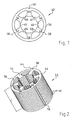
Fig. 1 zeigt ein Ausführungsbeispiel eines Einzelblechs 40 und Fig. 2 ein daraus hergestelltes Blechpaket (lamination stack) 42 für einen Innenläufermotor, dessen Rotor 43 in Fig. 4 schematisch angedeutet und vierpolig dargestellt ist. Naturgemäß sind auch andere Polzahlen möglich. 1 shows an exemplary embodiment of a
Das Blech 40 hat sechs ausgeprägte Statorpole 44, 46, 48, 50, 52 und 54 und einen magnetischen Rückschluss (yoke) 56. Außen sind die Bleche 40 mit Führungsnuten 58 für ihre Montage versehen.The
Zwischen den Statorpolen befinden sich Nuten 61 bis 66. Die Nut 61 befindet sich zwischen den Statorpolen 44 und 46, etc., wie in Fig. 1 dargestellt.
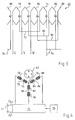
Fig. 3 zeigt die Anordnung einer dreiphasigen Statorwicklung 68 bekannter Bauart in den Nuten 61 bis 66. Z.B. geht von einem Anschluss U eine Verbindung zu einer Spule 70, die in den Nuten 61 und 62 liegt. Von dieser Spule 70 geht eine Querverbindung 72 zu einer Spule 74, die in einem Abstand von 360° el. (bezogen auf die Polteilung der Rotorpole) von der Spule 70 in den Nuten 64 und 65 liegt. Diese Spule 74 ist ihrerseits an einen Sternpunkt 76 angeschlossen, d.h. es handelt sich bei der dargestellten Wicklung 68 um eine Stern- oder Y-Schaltung. Naturgemäß wäre auch eine Dreiecksschaltung möglich, wie das dem Fachmann bekannt ist. Fig. 3 shows the arrangement of a three-phase stator winding 68 of known type in the
Von einem Anschluss V geht eine Verbindung zu einer Spule 78, die in den Nuten 62 und 63 liegt, und von dieser geht eine Querverbindung 80 zu einer Spule 82, die in den Nuten 65 und 66 angeordnet ist. Diese ist ebenfalls an den Sternpunkt 76 angeschlossen.A terminal V connects to a
Schließlich geht von einem Anschluss W eine Verbindung zu einer Spule 84, die in den Nuten 63 und 64 liegt, und von dieser geht eine Querverbindung 86 zu einer Spule 88, die in den Nuten 66 und 61 liegt und ebenfalls an den Sternpunkt 76 angeschlossen ist.Finally, a connection W goes to a
Fig. 4 zeigt in der üblichen Darstellung die sechs Spulen, ihre Querverbinder 72, 80 und 86, und den Sternpunkt 76. Jeder der drei Stränge U, V, W hat zwei in Serie geschaltete Spulen, die über eine Querverbindung miteinander verbunden sind, wie bei Fig. 3 beschrieben Fig. 4 shows in the usual representation the six coils, their
Die drei Stränge U, V, W sind an eine Endstufe 71 angeschlossen, die dazu dient, die Wicklung 68 mit einem dreiphasigen Strom zu versorgen, bevorzugt mit sinusförmigen Strömen, um ein möglichst gleichförmiges Drehmoment zu erreichen. Die Energie kommt aus einem Gleichstrom-Zwischenkreis mit einer positiven Leitung 73 und einer negativen Leitung 75, die ihre Energie z.B. aus einer Batterie 77 erhalten, deren Spannung meist mindestens 12 V beträgt. Zur Steuerung der Endstufe 71 dient ein Steuergerät 79, das dieser die entsprechenden Signale liefert, wie das dem Fachmann bekannt ist.The three strings U, V, W are connected to an
Die Fig. 5 bis 11 zeigen verschiedene Darstellungen eines U-förmigen Isolations-Formstücks 90, das nach seiner Montage einen der ausgeprägten Statorpole (Statorzähne) 44 bis 54 auf drei Seiten umgibt, wie das in Fig. 32 für die Einzelzähne 46 und 52 dargestellt ist, ebenso in Fig. 34 für die Einzelzähne 46 und 48. Das Formstück 90 hat ein kurzes Querstück 92, an dem zwei längere Schenkel 94, 96 angeordnet sind, die auf ihren voneinander abgewandten Seiten mit isolierenden Führungsnuten 98 versehen sind. Wie in Fig. 2 und 6 dargestellt, entspricht die Länge L der Schenkel 94, 96 im wesentlichen der Länge L (Fig. 2) des Blechpakets 42. Dieses Formstück 90 kann ggf. auch als Spritzgussteil direkt auf den entsprechenden Statorzahn aufgespritzt werden, was die Herstellung vereinfacht. 5 to 11 show various views of a U-shaped insulating fitting 90 which surrounds one of the salient Statorpole (stator teeth) 44 to 54 on three sides after its assembly, as shown in Fig. 32 for the
Die Fig. 12 bis 14 zeigen ein U-förmiges Blechteil 100, das einen Teil einer Spule der Statorwicklung 68 bildet und zum Anschluss der Phase U (oder V, oder W) verwendet wird. Dazu hat es ein Anschlussteil 102 mit drei Löchern 104, von denen gemäß Fig. 31 eines zum Anschluss eines Querverbinders 106 dient, der in den Fig. 27 bis 29 dargestellt ist. FIGS. 12 to 14 show a U-shaped
Die Querverbinder 106 für die drei Phasen U, V, W sind weitgehend, aber nicht vollständig, identisch. Ein solcher Querverbinder ist in den Fig. 27 bis 29 dargestellt. Sie haben jeweils einen Umfangsabschnitt 108, der sich über etwa 140° mech. erstreckt. Dieser geht in Fig. 28 am linken Ende über in einen nach innen ragenden Abschnitt 110, an dem ein Vorsprung 112 vorgesehen ist, der bei der Montage in eines der drei Löcher 104 (Fig. 12 und 13) gesteckt und mit diesem elektrisch verbunden wird, z.B. durch Schweißen, Löten, eine Crimpverbindung, oder dgl..The
An seinem in Fig. 28 rechten Ende hat der Querverbinder 106 einen nach innen ragenden Abschnitt 114, der an einer Stelle 116 abgekröpft ist und deshalb um einen Abstand D (Fig. 27) zum Abschnitt 108 parallel verschoben ist. Am Abschnitt 114 befindet sich eine Ausnehmung 118 zur Verbindung mit einem in den Fig. 18 bis 20 dargestellten Wicklungselement.At its right-hand end in FIG. 28, the cross-connector 106 has an inwardly projecting
Es ist darauf hinzuweisen, dass der Abstand D für die Phasen U, V und W verschieden ist, wie das aus Fig. 30 und 31 klar hervorgeht.It should be noted that the distance D for the phases U, V and W is different, as is clear from Figs. 30 and 31.
Das U-förmige Blechteil 100 hat, wie aus den Fig. 12 bis 14 hervorgeht, ein dachartiges Profil. Es hat an der Basis des U einen kurzen Abschnitt 122, der einstückig mit zwei längeren Schenkeln 124, 126 ausgebildet ist. Das Anschlussteil 102 ist am freien Ende des Schenkels 126 vorgesehen. Am freien Ende des Schenkels 124 befindet sich ein Vorsprung 128.The U-shaped
Fig. 33 zeigt, dass sich dort das Blechteil 100 im Formstück 90 in der obersten Führungsausnehmung 98 befindet, und dass der Vorsprung 128 mit einem bügelartigen Verbindungsteil 130 elektrisch verbunden ist, das eine Ausnehmung 132 hat, welche diesen Vorsprung 128 umgreift und in diesem Zustand mit ihm verschweißt wird.Fig. 33 shows that there is the
Die Länge des Blechteils 100 geht aus Fig. 13 hervor, wo eine Länge L' zum Vergleich eingetragen ist. Die Länge L' entspricht der Länge L des Blechpakets 42 plus der Dicke des Teil 92. Die Schenkel 124, 126 ragen also nur wenig aus dem Blechpaket 142 heraus, damit die Gesamtlänge des Stators 42 nach seiner Fertigstellung möglichst kurz ist.The length of the
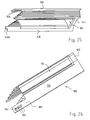
Die Fig. 15 bis 17 zeigen ein gestanztes und gebogenes Blechteil 134, das wie die anderen Blechteile aus Kupfer oder einer Kupferlegierung hergestellt ist. In Fig. 33 ist es das dritte Blechteil von unten. Es hat an der Basis des U ein kurzes Verbindungsteil 136, das einstückig mit zwei geraden Schenkeln 138, 140 ist, die beide an ihren freien Enden mit Verbindungselementen 138A, 140A versehen sind. Die Länge L' (gemäß obiger Definition) ist in Fig. 16 zum Vergleich eingetragen. Man erkennt, dass die Schenkel 138, 140 hier weiter aus dem Blechpaket 42 herausragen, vgl. Fig. 21. Figs. 15 to 17 show a stamped and bent
Die Fig. 18 bis 20 zeigen ein gestanztes und gebogenes Blechteil 142, welches in Fig. 33 die unterste Windung bildet. Es hat an der Basis des U ein kurzes Verbindungsteil 144, das einstückig mit zwei geraden Schenkeln 146, 148 ausgebildet ist, die an ihren freien Enden mit Verbindungselementen 146A, 148 A versehen sind. Die Länge L' (gemäß obiger Definition) ist in Fig.19 zum Vergleich eingetragen. Man erkennt, dass die Schenkel 146, 148 am weitesten aus dem Blechpaket 42 herausragen, und aus Fig. 33 erkennt man, dass diese Schenkel 146, 148 die geringste Breite haben, weil die Breite in Fig. 33 von oben nach unten abnimmt. Der Grund ist, dass gemäß Fig. 1 und 2 die Breite der Nuten 61 bis 66 von außen nach innen abnimmt, weshalb die Breite der Schenkel 146, 148 entsprechend angepasst werden muss, vgl. Fig. 32. Dort erkennt man, dass sich die Schenkel der Windungselemente jeweils bis fast zur Mitte einer Nut erstrecken, um einen hohen Kupferfüllfaktor zu erzielen. Der Schenkel 126 ist breiter und bildet eine Ausnahme von dieser Regel, und deshalb ist der ihm gegenüber liegende Schenkel der benachbarten Spule entsprechend schmaler. Figs. 18 to 20 show a punched and bent
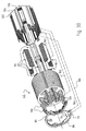
Fig. 21 zeigt, wie die Windungselemente 100, 134, 142 in ein Formstück 90 eingeschoben sind. Zwischen den Windungselementen 100 und 134 befinden sich noch zwei Windungselemente 150, 152, welche die gleiche Grundform haben, wie das Windungselement 134, aber etwas kürzer und breiter sind, als dieses. Ebenso befindet sich zwischen den Windungselementen 134 und 142 ein Windungselement 154, das die gleiche Grundform hat wie das Windungselement 134, aber etwas länger und etwas schmaler ist als dieses. Die Windungselemente 150, 152, 154 sind aus diesem Grunde nicht separat dargestellt. Die Abnahme der Breite ist aus Fig. 33 klar ersichtlich und dient, wie erläutert, dem Erzielen eines guten Kupferfüllfaktors. Die Form der Anschlusselemente an den Enden der Schenkel bzw. Stäbe ergibt sich aus den Fig. 24, 25, 26 und 33. Fig. 21 shows how the winding
Die Fig. 21 bis 26 zeigen aus verschiedenen Blickwinkeln ein mit Windungselementen gefülltes Formstück 90. Falls die Formstücke 90 separat hergestellt werden, füllt man sie mit den Windungselementen, bevor sie im Blechpaket 42 montiert werden, vgl. Fig. 30, wo das links dargestellt und durch eine Linie 160 symbolisiert ist. Anschließend werden die gefüllten Formstücke 90 in das Blechpaket 42 eingeschoben. Alternativ können die Formstücke 90 durch Spritzguss direkt im Blechpaket 42 hergestellt werden, und in diesem Fall werden sie im Blechpaket 42 mit den Windungselementen bestückt.FIGS. 21 to 26 show, from various angles, a molded
Nach dem Bestücken werden die Verbinder 130 an den Windungselementen angebracht, was durch ein gestrichelte Linie 162 symbolisiert ist. Danach werden die Querverbinder 72, 80, 86 montiert, symbolisiert durch eine Linie 164, und als letztes folgt die Montage des Verbinders 76 für den Sternpunkt, symbolisiert durch eine Linie 166.After loading, the
Dabei ergibt sich in einer perspektivischen Darstellung für den Strang U das Bild gemäß Fig. 31 und 32. In Fig. 31 ist unten die - noch unfertige - Spule 70 (vgl. Fig. 4) mit ihrem Anschluss U dargestellt. Mit ihrem innersten Windungselement 142 und dessen Anschluss 148A ist der Querverbinder 72, wie er in den Fig. 27 bis 29 dargestellt ist, mit seiner Ausnehmung 118 elektrisch verbunden. (Das Maß D, das in Fig. 27 dargestellt ist, ist bei Fig. 31 etwas größer). Der Querverbinder 72 führt gemäß Fig. 31 und 32 zur Spule 74 und dort zum untersten Loch 104 des Windungselements 100, welches in den Fig. 12 bis 14 dargestellt ist. Der Anschluss 112 des Querverbinders 72 ragt in dieses Loch 104 und ist mit ihm elektrisch gut leitend verbunden.This results in a perspective view of the strand U the image shown in FIG. 31 and 32. In Fig. 31 below - the still unfinished - coil 70 (see Fig. 4) with its port U shown. With its innermost winding
Das am weitesten innen liegende Windungselement 142 der Spule 74 ist mit seinem Anschluss 148 mit dem Sternpunktleiter 76 elektrisch gut leitend verbunden, dessen Form aus den Fig. 31 und 32 klar ersichtlich ist. Es handelt sich um ein gestanztes Teil aus Kupferblech.The innermost winding
Fig. 32 zeigt zur besseren Orientierung auch die Lage der Statorpole 44 bis 54 und der Nuten 61 bis 66, wie sie auch in den Fig. 1 bis 3 dargestellt sind. Ferner ist in den Fig. 31 und 32 auch die Lage der Querverbinder 80 und 86 eingezeichnet, obwohl diese für den dargestellten Strang U keine Funktion haben und deshalb nur frei im Raume schweben. Fig. 32 shows for better orientation and the position of the
In Fig. 32 ist auch der Rotor 43 angedeutet. Dieser hat vier Magnete 170, 172, 174, 176, deren Polarität in der üblichen Weise mit N und S angedeutet ist und die in Ausnehmungen eines Blechpakets 178 eingebettet sind (embedded magnets). Der Rotor 43 ist durch einen Luftspalt 180 vom Blechpaket 42 getrennt.In Fig. 32 and the
Fig. 33 zeigt, wie der Anschluss 128 des Windungsteils 100 (in der radial äußersten Lage) über das bügelartige Verbindungsteil 130 mit einem Anschluss 182 des Windungsteils 150 verbunden wird. Dazu hat der Bügel 130 links eine Ausnehmung 132, die mit dem Anschluss 128 elektrisch gut leitend verbunden wird, und rechts hat er eine Ausnehmung 184, die mit dem Anschluss 182 elektrisch gut leitend verbunden wird. FIG. 33 shows how the
Der Strom geht also in Fig. 33 vom Anschluss 102 durch das Windungselement 100 zum Anschluss 128, von dort über den Bügel 130 zum Anschluss 182 des Windungselements 150, dann durch dieses zu dessen Anschluss 186, anschließend von diesem Anschluss über einen nur symbolisch angedeuteten Verbindungsbügel 188 zu einem Anschluss 190 des Windungselements 152, dann durch dieses zu dessen Anschluss 192.The current thus flows in FIG. 33 from the terminal 102 through the winding
Vom Anschluss 192 fließt der elektrische Strom über einen nur symbolisch angedeuteten Verbindungsbügel 194 zum Anschluss 140A des Windungselements 134, dann durch dieses zu dessen Anschluss 138A, und von diesem über einen nur symbolisch angedeuteten Verbindungsbügel 196 zu einem Anschluss 198 des Windungselements 154. Dann fließt der Strom durch das Element 154 zu dessen Anschluss 200 und von dort über einen symbolisch angedeuteten Verbindungsbügel 202 zum Anschluss 146A des Windungselements 142, und durch dieses zu dessen Anschluss 148A, vgl. Fig. 18.From the terminal 192, the electric current flows via a
Vom Anschluss 148A fließt der Strom entweder über einen Querverbinder (vgl. die Fig. 27 bis 29) zur nächsten Spule dieses Stranges, oder zum Sternpunkt 76.From the terminal 148A, the current either flows through a cross connector (see Figures 27 to 29) to the next coil of this string, or
Die Fig. 31 bis 33 zeigen nur die untersten Verbindungsbügel 130 der Spulen 70 und 74, um die Zeichnung übersichtlich zu halten.Figs. 31 to 33 show only the
Bei der Herstellung geht man so vor, dass man nach der Montage der Formstücke 90 mit den Windungselementen (vgl. Fig. 21 bis 26) als erstes die untersten Verbindungsbügel 130 für alle sechs Spulen 70, 74, 78, 82, 84, 88 an den betreffenden Windungselementen anbringt und elektrisch gut leitend mit diesen verbindet. Man verarbeitet also bevorzugt die Verbindungselemente einer Ebene gleichzeitig.In the production, the procedure is such that, after the assembly of the shaped
Als nächstes werden dann die Bügel 188 (Fig. 33 bis 36) der nächsten Lage angebracht und elektrisch gut leitend verbunden, dann nacheinander die Bügel 194, 196 und 202, so dass die einzelnen Spulen durchgehend stromleitend sind.Next, the straps 188 (Figures 33-36) of the next layer are then attached and electrically conductively connected, then sequentially the
Anschließend werden die einzelnen Querverbinder montiert, beginnend mit dem untersten Querverbinder 72, dessen Montage bei den Fig. 30 und 31 bereits beschrieben wurde, danach der Querverbinder 86, und als letztes der Querverbinder 80. Die drei Löcher 104 (Fig. 12) im Blechteil 100 ermöglichen eine Verbindung mit einem Querverbinder unabhängig davon, in welcher Ebene sich dieser befindet.Subsequently, the individual transverse connectors are mounted, beginning with the
Wenn die Querverbinder montiert und elektrisch gut leitend verbunden sind, wird der Sternpunkt-Verbinder 76 montiert, was bereits bei Fig. 30 und 31 beschrieben wurde.When the cross connectors are mounted and electrically well connected, is the
Das bewickelte Statorblechpaket 42 hat dann seine fertige Gestalt, wie sie in den Fig. 34 bis 36 dargestellt ist, und es wird in ein entsprechendes (nicht dargestelltes) Gehäuse eingebaut, welches das Statorblechpaket hermetisch geschlossen umgibt, und der Rotor 34 wird in (nicht dargestellten) Lagern dieses Gehäuses in der üblichen Weise gelagert.The wound
Die beschriebenen elektrischen Verbindungen können widerstandsarm ausgeführt werden, so dass die Statorwicklung wegen des im Mittelwert großen Querschnitts der elektrischen Leiter einen niedrigen Innenwiderstand hat und man auch bei niedrigen Spannungen der Batterie 77 (oder einer sonstigen Spannungsquelle, z. B. einer Brennstoffzelle) ein starkes Drehmoment erzeugen kann.The electrical connections described can be carried out with low resistance, so that the stator winding has a low internal resistance because of the average cross-section of the electrical conductors and a strong one even at low voltages of the battery 77 (or another voltage source, eg a fuel cell) Can generate torque.
Das (nicht dargestellte) Gehäuse wird bevorzugt nach außen hermetisch abgeschlossen, um das Eindringen von Fremdkörpern zu vermeiden, welche einen Windungsschluss verursachen könnten. Die Windungselemente können durch einen Ölkreislauf gekühlt werden, um höhere Motorleistungen zu erreichen. Ferner ist es auch möglich, nach der Montage der Windungselemente den gesamten Stator mit einem geeigneten Isolator zu umgießen, z. B. mit einem isolierenden Kunstharz. Naturgemäß sind im Rahmen der Erfindung Modifikationen dieser Art für den Fachmann problemlos möglich.The housing (not shown) is preferably hermetically sealed to the outside to prevent the ingress of foreign bodies which could cause a short circuit. The winding elements can be cooled by an oil circuit to achieve higher engine power. Furthermore, it is also possible to encase the entire stator with a suitable insulator after assembly of the winding elements, for. B. with an insulating resin. Naturally, within the scope of the invention, modifications of this type are easily possible for the person skilled in the art.
Claims (10)
Applications Claiming Priority (1)
| Application Number | Priority Date | Filing Date | Title |
|---|---|---|---|
| DE102004046544A DE102004046544A1 (en) | 2004-09-20 | 2004-09-20 | Engine, especially for low voltage |
Publications (2)
| Publication Number | Publication Date |
|---|---|
| EP1638188A1 true EP1638188A1 (en) | 2006-03-22 |
| EP1638188B1 EP1638188B1 (en) | 2007-05-02 |
Family
ID=34937816
Family Applications (1)
| Application Number | Title | Priority Date | Filing Date |
|---|---|---|---|
| EP05014930A Not-in-force EP1638188B1 (en) | 2004-09-20 | 2005-07-09 | Motor, especially for low voltage |
Country Status (3)
| Country | Link |
|---|---|
| EP (1) | EP1638188B1 (en) |
| AT (1) | ATE361575T1 (en) |
| DE (2) | DE102004046544A1 (en) |
Cited By (4)
| Publication number | Priority date | Publication date | Assignee | Title |
|---|---|---|---|---|
| EP1947755A1 (en) * | 2007-01-19 | 2008-07-23 | ENGEL Elektroantriebe GmbH | Stator of an electric machine |
| EP1988619A1 (en) * | 2007-04-25 | 2008-11-05 | Hitachi, Ltd. | Rotary electric machine, power distribution unit therefor and method for assembling rotary electric machine |
| CN106471717A (en) * | 2014-06-09 | 2017-03-01 | 日产自动车株式会社 | The manufacture method of flat wire stator coil |
| CN108141084A (en) * | 2015-11-09 | 2018-06-08 | 大陆汽车有限公司 | Electrically powered machine and relative manufacturing process with the circuit board assemblies connected for winding |
Families Citing this family (4)
| Publication number | Priority date | Publication date | Assignee | Title |
|---|---|---|---|---|
| DE102009034660A1 (en) | 2008-08-01 | 2010-02-04 | Ebm-Papst St. Georgen Gmbh & Co. Kg | Electrical machine i.e. electronically commutated motor, has pole windings dividing metal shaped part into spiral running windings whose cross sections are constant on predominant part of longitudinal extension of spiral windings |
| DE102011088658A1 (en) * | 2011-12-15 | 2013-06-20 | Zf Friedrichshafen Ag | Stator of an electrical machine with voltage insulation |
| DE102015208414A1 (en) | 2015-05-06 | 2016-11-10 | Robert Bosch Gmbh | Winding tooth of an electric machine |
| DE102021127073A1 (en) | 2021-10-19 | 2023-04-20 | Bayerische Motoren Werke Aktiengesellschaft | Rotor with cross-connectors, electrical machine and method for producing a rotor |
Citations (7)
| Publication number | Priority date | Publication date | Assignee | Title |
|---|---|---|---|---|
| GB622032A (en) * | 1947-03-04 | 1949-04-26 | British Thomson Houston Co Ltd | Improvements relating to the windings of dynamo-electric machines |
| DE1018528B (en) * | 1955-12-22 | 1957-10-31 | Siemens Ag | Magnetic pole with a flat-edge wound pole coil, especially a reversible pole |
| US3333131A (en) * | 1964-12-01 | 1967-07-25 | Westinghouse Electric Corp | Commutating pole assembly for a dynamoelectric machine |
| US3543067A (en) * | 1968-03-25 | 1970-11-24 | Westinghouse Electric Corp | Commutating field coil insulation and support structure |
| US20010010442A1 (en) * | 2000-01-31 | 2001-08-02 | Hitachi, Ltd. And Hitachi Car Engineering Co., Tld. | Stator of rotating electric machine |
| JP2002044894A (en) * | 2000-07-26 | 2002-02-08 | Aisin Seiki Co Ltd | Insulation material for rotating electric machine |
| EP1207613A2 (en) * | 2000-11-15 | 2002-05-22 | Hitachi, Ltd. | A stacked coil assembly for a stator |
-
2004
- 2004-09-20 DE DE102004046544A patent/DE102004046544A1/en not_active Withdrawn
-
2005
- 2005-07-09 AT AT05014930T patent/ATE361575T1/en not_active IP Right Cessation
- 2005-07-09 DE DE502005000654T patent/DE502005000654D1/en active Active
- 2005-07-09 EP EP05014930A patent/EP1638188B1/en not_active Not-in-force
Patent Citations (7)
| Publication number | Priority date | Publication date | Assignee | Title |
|---|---|---|---|---|
| GB622032A (en) * | 1947-03-04 | 1949-04-26 | British Thomson Houston Co Ltd | Improvements relating to the windings of dynamo-electric machines |
| DE1018528B (en) * | 1955-12-22 | 1957-10-31 | Siemens Ag | Magnetic pole with a flat-edge wound pole coil, especially a reversible pole |
| US3333131A (en) * | 1964-12-01 | 1967-07-25 | Westinghouse Electric Corp | Commutating pole assembly for a dynamoelectric machine |
| US3543067A (en) * | 1968-03-25 | 1970-11-24 | Westinghouse Electric Corp | Commutating field coil insulation and support structure |
| US20010010442A1 (en) * | 2000-01-31 | 2001-08-02 | Hitachi, Ltd. And Hitachi Car Engineering Co., Tld. | Stator of rotating electric machine |
| JP2002044894A (en) * | 2000-07-26 | 2002-02-08 | Aisin Seiki Co Ltd | Insulation material for rotating electric machine |
| EP1207613A2 (en) * | 2000-11-15 | 2002-05-22 | Hitachi, Ltd. | A stacked coil assembly for a stator |
Non-Patent Citations (1)
| Title |
|---|
| PATENT ABSTRACTS OF JAPAN vol. 2002, no. 06 4 June 2002 (2002-06-04) * |
Cited By (10)
| Publication number | Priority date | Publication date | Assignee | Title |
|---|---|---|---|---|
| EP1947755A1 (en) * | 2007-01-19 | 2008-07-23 | ENGEL Elektroantriebe GmbH | Stator of an electric machine |
| EP1988619A1 (en) * | 2007-04-25 | 2008-11-05 | Hitachi, Ltd. | Rotary electric machine, power distribution unit therefor and method for assembling rotary electric machine |
| US7952245B2 (en) | 2007-04-25 | 2011-05-31 | Hitachi, Ltd. | Power distribution unit for rotary electric machine with linear conductor connecting ring having terminal section with axially extending hole for connecting stator coil, and method for assembling rotary electric machine |
| CN106471717A (en) * | 2014-06-09 | 2017-03-01 | 日产自动车株式会社 | The manufacture method of flat wire stator coil |
| EP3154159A4 (en) * | 2014-06-09 | 2017-04-12 | Nissan Motor Co., Ltd | Flat-wire stator coil manufacturing method |
| US9825513B2 (en) | 2014-06-09 | 2017-11-21 | Nissan Motor Co., Ltd. | Rectangular wire stator coil manufacturing method |
| CN106471717B (en) * | 2014-06-09 | 2018-12-07 | 日产自动车株式会社 | The manufacturing method of flat wire stator coil |
| CN108141084A (en) * | 2015-11-09 | 2018-06-08 | 大陆汽车有限公司 | Electrically powered machine and relative manufacturing process with the circuit board assemblies connected for winding |
| US20180262072A1 (en) * | 2015-11-09 | 2018-09-13 | Continental Automotive Gmbh | Electrical machine having a printed circuit board arrangement for winding interconnection and associated production method |
| US10897170B2 (en) * | 2015-11-09 | 2021-01-19 | Vitesco Technologies GmbH | Electrical machine having a printed circuit board arrangement for winding interconnection and associated production method |
Also Published As
| Publication number | Publication date |
|---|---|
| ATE361575T1 (en) | 2007-05-15 |
| DE502005000654D1 (en) | 2007-06-14 |
| EP1638188B1 (en) | 2007-05-02 |
| DE102004046544A1 (en) | 2006-04-27 |
Similar Documents
| Publication | Publication Date | Title |
|---|---|---|
| EP1526628B1 (en) | Connection unit for a stator of an electric motor | |
| EP2139094B1 (en) | Stator and connecting arrangement of an electric machine | |
| EP1638188B1 (en) | Motor, especially for low voltage | |
| EP1810388B1 (en) | Electric motor | |
| EP3298679A1 (en) | Stator for an electric machine and method for producing same | |
| EP3078099B1 (en) | Stator for an electronically commutated direct current motor | |
| WO2010066491A2 (en) | Electric motor, in particular servo or drive motor in motor vehicles | |
| DE202009000415U1 (en) | Electronically commutated motor | |
| DE112013003484T5 (en) | Integrated phase connection insulator with single phase separator | |
| DE102004036368A1 (en) | Electric motor for auto, has stator with slotted lamination stack having end face including set of annular shaped jumper rings and neutral ring, where neutral ring has radial projections extending along preset stator teeth to head | |
| DE102014201637A1 (en) | Track for a stator, stator, electric motor and method of manufacturing a stator | |
| DE102015211786A1 (en) | stator | |
| WO2016180588A1 (en) | Stator for an electrical machine having an encapsulated interconnection device, and electrical machine having such a stator | |
| WO2003063322A2 (en) | Stator assembly | |
| DE102017101073A1 (en) | Stator package and method of making a stator pack | |
| DE102006019586A1 (en) | Asynchronous motor with inner rotor | |
| DE102019004591A1 (en) | Electric motor with an interconnection unit and method for producing an electric motor with an interconnection unit | |
| WO2010066493A2 (en) | Stator in an electric motor | |
| DE102006051458A1 (en) | Electrical motor has a commutator structure with short circuit and and overload protection elements | |
| WO2007014570A1 (en) | Electric motor and method for its production | |
| DE202005014302U1 (en) | Motor especially for low voltage has shaped piece to insulate stator windings from stator poles and from one another | |
| EP3311469A1 (en) | Pre-formed coil, winding structure, and stator for a generator of a wind turbine and method for producing a stator | |
| DE3817912A1 (en) | STATOR OF AN AC MOTOR ARRANGED IN MOTOR VEHICLES | |
| EP3824529A1 (en) | Electric motor comprising a wiring unit and method for producing an electric motor with comprising a wiring unit | |
| DE102019004589A1 (en) | Electric motor with an interconnection unit and method for producing an electric motor with an interconnection unit |
Legal Events
| Date | Code | Title | Description |
|---|---|---|---|
| PUAI | Public reference made under article 153(3) epc to a published international application that has entered the european phase |
Free format text: ORIGINAL CODE: 0009012 |
|
| 17P | Request for examination filed |
Effective date: 20050920 |
|
| AK | Designated contracting states |
Kind code of ref document: A1 Designated state(s): AT BE BG CH CY CZ DE DK EE ES FI FR GB GR HU IE IS IT LI LT LU LV MC NL PL PT RO SE SI SK TR |
|
| AX | Request for extension of the european patent |
Extension state: AL BA HR MK YU |
|
| AKX | Designation fees paid |
Designated state(s): AT BE BG CH CY CZ DE DK EE ES FI FR GB GR HU IE IS IT LI LT LU LV MC NL PL PT RO SE SI SK TR |
|
| GRAP | Despatch of communication of intention to grant a patent |
Free format text: ORIGINAL CODE: EPIDOSNIGR1 |
|
| GRAS | Grant fee paid |
Free format text: ORIGINAL CODE: EPIDOSNIGR3 |
|
| GRAA | (expected) grant |
Free format text: ORIGINAL CODE: 0009210 |
|
| AK | Designated contracting states |
Kind code of ref document: B1 Designated state(s): AT BE BG CH CY CZ DE DK EE ES FI FR GB GR HU IE IS IT LI LT LU LV MC NL PL PT RO SE SI SK TR |
|
| PG25 | Lapsed in a contracting state [announced via postgrant information from national office to epo] |
Ref country code: FI Free format text: LAPSE BECAUSE OF FAILURE TO SUBMIT A TRANSLATION OF THE DESCRIPTION OR TO PAY THE FEE WITHIN THE PRESCRIBED TIME-LIMIT Effective date: 20070502 |
|
| REG | Reference to a national code |
Ref country code: GB Ref legal event code: FG4D Free format text: NOT ENGLISH |
|
| REG | Reference to a national code |
Ref country code: CH Ref legal event code: EP |
|
| REG | Reference to a national code |
Ref country code: IE Ref legal event code: FG4D Free format text: LANGUAGE OF EP DOCUMENT: GERMAN |
|
| REF | Corresponds to: |
Ref document number: 502005000654 Country of ref document: DE Date of ref document: 20070614 Kind code of ref document: P |
|
| GBT | Gb: translation of ep patent filed (gb section 77(6)(a)/1977) |
Effective date: 20070605 |
|
| REG | Reference to a national code |
Ref country code: SE Ref legal event code: TRGR |
|
| PG25 | Lapsed in a contracting state [announced via postgrant information from national office to epo] |
Ref country code: ES Free format text: LAPSE BECAUSE OF FAILURE TO SUBMIT A TRANSLATION OF THE DESCRIPTION OR TO PAY THE FEE WITHIN THE PRESCRIBED TIME-LIMIT Effective date: 20070813 |
|
| PG25 | Lapsed in a contracting state [announced via postgrant information from national office to epo] |
Ref country code: IS Free format text: LAPSE BECAUSE OF FAILURE TO SUBMIT A TRANSLATION OF THE DESCRIPTION OR TO PAY THE FEE WITHIN THE PRESCRIBED TIME-LIMIT Effective date: 20070902 |
|
| NLV1 | Nl: lapsed or annulled due to failure to fulfill the requirements of art. 29p and 29m of the patents act | ||
| ET | Fr: translation filed | ||
| PG25 | Lapsed in a contracting state [announced via postgrant information from national office to epo] |
Ref country code: PL Free format text: LAPSE BECAUSE OF FAILURE TO SUBMIT A TRANSLATION OF THE DESCRIPTION OR TO PAY THE FEE WITHIN THE PRESCRIBED TIME-LIMIT Effective date: 20070502 |
|
| REG | Reference to a national code |
Ref country code: IE Ref legal event code: FD4D |
|
| BERE | Be: lapsed |
Owner name: EBM-PAPST ST. GEORGEN G.M.B.H. & CO. KG Effective date: 20070731 |
|
| PG25 | Lapsed in a contracting state [announced via postgrant information from national office to epo] |
Ref country code: PT Free format text: LAPSE BECAUSE OF FAILURE TO SUBMIT A TRANSLATION OF THE DESCRIPTION OR TO PAY THE FEE WITHIN THE PRESCRIBED TIME-LIMIT Effective date: 20071002 Ref country code: SI Free format text: LAPSE BECAUSE OF FAILURE TO SUBMIT A TRANSLATION OF THE DESCRIPTION OR TO PAY THE FEE WITHIN THE PRESCRIBED TIME-LIMIT Effective date: 20070502 Ref country code: NL Free format text: LAPSE BECAUSE OF FAILURE TO SUBMIT A TRANSLATION OF THE DESCRIPTION OR TO PAY THE FEE WITHIN THE PRESCRIBED TIME-LIMIT Effective date: 20070502 Ref country code: CZ Free format text: LAPSE BECAUSE OF FAILURE TO SUBMIT A TRANSLATION OF THE DESCRIPTION OR TO PAY THE FEE WITHIN THE PRESCRIBED TIME-LIMIT Effective date: 20070502 Ref country code: DK Free format text: LAPSE BECAUSE OF FAILURE TO SUBMIT A TRANSLATION OF THE DESCRIPTION OR TO PAY THE FEE WITHIN THE PRESCRIBED TIME-LIMIT Effective date: 20070502 Ref country code: IE Free format text: LAPSE BECAUSE OF FAILURE TO SUBMIT A TRANSLATION OF THE DESCRIPTION OR TO PAY THE FEE WITHIN THE PRESCRIBED TIME-LIMIT Effective date: 20070502 Ref country code: BG Free format text: LAPSE BECAUSE OF FAILURE TO SUBMIT A TRANSLATION OF THE DESCRIPTION OR TO PAY THE FEE WITHIN THE PRESCRIBED TIME-LIMIT Effective date: 20070802 |
|
| PG25 | Lapsed in a contracting state [announced via postgrant information from national office to epo] |
Ref country code: SK Free format text: LAPSE BECAUSE OF FAILURE TO SUBMIT A TRANSLATION OF THE DESCRIPTION OR TO PAY THE FEE WITHIN THE PRESCRIBED TIME-LIMIT Effective date: 20070502 Ref country code: LV Free format text: LAPSE BECAUSE OF FAILURE TO SUBMIT A TRANSLATION OF THE DESCRIPTION OR TO PAY THE FEE WITHIN THE PRESCRIBED TIME-LIMIT Effective date: 20070502 Ref country code: LT Free format text: LAPSE BECAUSE OF FAILURE TO SUBMIT A TRANSLATION OF THE DESCRIPTION OR TO PAY THE FEE WITHIN THE PRESCRIBED TIME-LIMIT Effective date: 20070502 |
|
| PLBE | No opposition filed within time limit |
Free format text: ORIGINAL CODE: 0009261 |
|
| STAA | Information on the status of an ep patent application or granted ep patent |
Free format text: STATUS: NO OPPOSITION FILED WITHIN TIME LIMIT |
|
| 26N | No opposition filed |
Effective date: 20080205 |
|
| PG25 | Lapsed in a contracting state [announced via postgrant information from national office to epo] |
Ref country code: MC Free format text: LAPSE BECAUSE OF NON-PAYMENT OF DUE FEES Effective date: 20070731 Ref country code: GR Free format text: LAPSE BECAUSE OF FAILURE TO SUBMIT A TRANSLATION OF THE DESCRIPTION OR TO PAY THE FEE WITHIN THE PRESCRIBED TIME-LIMIT Effective date: 20070803 |
|
| PG25 | Lapsed in a contracting state [announced via postgrant information from national office to epo] |
Ref country code: RO Free format text: LAPSE BECAUSE OF FAILURE TO SUBMIT A TRANSLATION OF THE DESCRIPTION OR TO PAY THE FEE WITHIN THE PRESCRIBED TIME-LIMIT Effective date: 20070502 |
|
| PG25 | Lapsed in a contracting state [announced via postgrant information from national office to epo] |
Ref country code: BE Free format text: LAPSE BECAUSE OF NON-PAYMENT OF DUE FEES Effective date: 20070731 |
|
| PG25 | Lapsed in a contracting state [announced via postgrant information from national office to epo] |
Ref country code: AT Free format text: LAPSE BECAUSE OF NON-PAYMENT OF DUE FEES Effective date: 20070709 |
|
| PG25 | Lapsed in a contracting state [announced via postgrant information from national office to epo] |
Ref country code: EE Free format text: LAPSE BECAUSE OF FAILURE TO SUBMIT A TRANSLATION OF THE DESCRIPTION OR TO PAY THE FEE WITHIN THE PRESCRIBED TIME-LIMIT Effective date: 20070502 |
|
| PG25 | Lapsed in a contracting state [announced via postgrant information from national office to epo] |
Ref country code: CY Free format text: LAPSE BECAUSE OF FAILURE TO SUBMIT A TRANSLATION OF THE DESCRIPTION OR TO PAY THE FEE WITHIN THE PRESCRIBED TIME-LIMIT Effective date: 20070502 |
|
| PG25 | Lapsed in a contracting state [announced via postgrant information from national office to epo] |
Ref country code: LU Free format text: LAPSE BECAUSE OF NON-PAYMENT OF DUE FEES Effective date: 20070709 |
|
| PG25 | Lapsed in a contracting state [announced via postgrant information from national office to epo] |
Ref country code: HU Free format text: LAPSE BECAUSE OF FAILURE TO SUBMIT A TRANSLATION OF THE DESCRIPTION OR TO PAY THE FEE WITHIN THE PRESCRIBED TIME-LIMIT Effective date: 20071103 Ref country code: TR Free format text: LAPSE BECAUSE OF FAILURE TO SUBMIT A TRANSLATION OF THE DESCRIPTION OR TO PAY THE FEE WITHIN THE PRESCRIBED TIME-LIMIT Effective date: 20070502 |
|
| REG | Reference to a national code |
Ref country code: CH Ref legal event code: PL |
|
| PG25 | Lapsed in a contracting state [announced via postgrant information from national office to epo] |
Ref country code: CH Free format text: LAPSE BECAUSE OF NON-PAYMENT OF DUE FEES Effective date: 20090731 Ref country code: LI Free format text: LAPSE BECAUSE OF NON-PAYMENT OF DUE FEES Effective date: 20090731 |
|
| REG | Reference to a national code |
Ref country code: FR Ref legal event code: PLFP Year of fee payment: 11 |
|
| REG | Reference to a national code |
Ref country code: DE Ref legal event code: R084 Ref document number: 502005000654 Country of ref document: DE |
|
| PGFP | Annual fee paid to national office [announced via postgrant information from national office to epo] |
Ref country code: IT Payment date: 20150422 Year of fee payment: 11 Ref country code: FR Payment date: 20150610 Year of fee payment: 11 |
|
| PGFP | Annual fee paid to national office [announced via postgrant information from national office to epo] |
Ref country code: GB Payment date: 20150805 Year of fee payment: 11 |
|
| PGFP | Annual fee paid to national office [announced via postgrant information from national office to epo] |
Ref country code: SE Payment date: 20150720 Year of fee payment: 11 |
|
| REG | Reference to a national code |
Ref country code: SE Ref legal event code: EUG |
|
| GBPC | Gb: european patent ceased through non-payment of renewal fee |
Effective date: 20160709 |
|
| PG25 | Lapsed in a contracting state [announced via postgrant information from national office to epo] |
Ref country code: SE Free format text: LAPSE BECAUSE OF NON-PAYMENT OF DUE FEES Effective date: 20160710 Ref country code: FR Free format text: LAPSE BECAUSE OF NON-PAYMENT OF DUE FEES Effective date: 20160801 |
|
| REG | Reference to a national code |
Ref country code: FR Ref legal event code: ST Effective date: 20170331 |
|
| PG25 | Lapsed in a contracting state [announced via postgrant information from national office to epo] |
Ref country code: GB Free format text: LAPSE BECAUSE OF NON-PAYMENT OF DUE FEES Effective date: 20160709 |
|
| PG25 | Lapsed in a contracting state [announced via postgrant information from national office to epo] |
Ref country code: IT Free format text: LAPSE BECAUSE OF NON-PAYMENT OF DUE FEES Effective date: 20160709 |
|
| REG | Reference to a national code |
Ref country code: DE Ref legal event code: R231 Ref document number: 502005000654 Country of ref document: DE |
|
| PG25 | Lapsed in a contracting state [announced via postgrant information from national office to epo] |
Ref country code: DE Free format text: LAPSE BECAUSE OF THE APPLICANT RENOUNCES Effective date: 20180818 |
|
| PGFP | Annual fee paid to national office [announced via postgrant information from national office to epo] |
Ref country code: DE Payment date: 20180703 Year of fee payment: 14 |