EP1635906B2 - Traitement de maladies retiniennes par stimulation des structures superficielles - Google Patents
Traitement de maladies retiniennes par stimulation des structures superficielles Download PDFInfo
- Publication number
- EP1635906B2 EP1635906B2 EP04755009.0A EP04755009A EP1635906B2 EP 1635906 B2 EP1635906 B2 EP 1635906B2 EP 04755009 A EP04755009 A EP 04755009A EP 1635906 B2 EP1635906 B2 EP 1635906B2
- Authority
- EP
- European Patent Office
- Prior art keywords
- electrode
- eyeball
- surface structure
- contact
- source
- Prior art date
- Legal status (The legal status is an assumption and is not a legal conclusion. Google has not performed a legal analysis and makes no representation as to the accuracy of the status listed.)
- Expired - Lifetime
Links
- 230000000638 stimulation Effects 0.000 title claims description 53
- 210000005252 bulbus oculi Anatomy 0.000 title claims description 30
- 208000017442 Retinal disease Diseases 0.000 title claims description 8
- 230000003412 degenerative effect Effects 0.000 title claims description 6
- 210000003786 sclera Anatomy 0.000 claims description 21
- 210000000795 conjunctiva Anatomy 0.000 claims description 16
- 210000003205 muscle Anatomy 0.000 claims description 13
- 206010025421 Macule Diseases 0.000 claims description 12
- 230000001684 chronic effect Effects 0.000 claims description 11
- 230000004936 stimulating effect Effects 0.000 claims description 10
- 230000001747 exhibiting effect Effects 0.000 claims description 5
- 230000006698 induction Effects 0.000 claims description 5
- 210000001508 eye Anatomy 0.000 description 60
- 210000001525 retina Anatomy 0.000 description 40
- NCYCYZXNIZJOKI-UHFFFAOYSA-N vitamin A aldehyde Natural products O=CC=C(C)C=CC=C(C)C=CC1=C(C)CCCC1(C)C NCYCYZXNIZJOKI-UHFFFAOYSA-N 0.000 description 27
- 230000002207 retinal effect Effects 0.000 description 24
- 238000000034 method Methods 0.000 description 18
- 230000004382 visual function Effects 0.000 description 12
- 210000004027 cell Anatomy 0.000 description 11
- 230000007850 degeneration Effects 0.000 description 11
- 230000000007 visual effect Effects 0.000 description 11
- 210000001519 tissue Anatomy 0.000 description 10
- 210000004087 cornea Anatomy 0.000 description 9
- 108091008695 photoreceptors Proteins 0.000 description 8
- 201000007737 Retinal degeneration Diseases 0.000 description 7
- NCYCYZXNIZJOKI-OVSJKPMPSA-N Retinaldehyde Chemical compound O=C\C=C(/C)\C=C\C=C(/C)\C=C\C1=C(C)CCCC1(C)C NCYCYZXNIZJOKI-OVSJKPMPSA-N 0.000 description 7
- 238000010586 diagram Methods 0.000 description 7
- 210000000744 eyelid Anatomy 0.000 description 7
- 210000001328 optic nerve Anatomy 0.000 description 7
- 239000007943 implant Substances 0.000 description 6
- 238000010420 art technique Methods 0.000 description 5
- 230000003915 cell function Effects 0.000 description 5
- 201000010099 disease Diseases 0.000 description 5
- 208000037265 diseases, disorders, signs and symptoms Diseases 0.000 description 5
- 230000000694 effects Effects 0.000 description 5
- 230000004438 eyesight Effects 0.000 description 5
- 230000002093 peripheral effect Effects 0.000 description 5
- 241000282412 Homo Species 0.000 description 4
- 108090000099 Neurotrophin-4 Proteins 0.000 description 4
- 206010057430 Retinal injury Diseases 0.000 description 4
- 208000007014 Retinitis pigmentosa Diseases 0.000 description 4
- 230000015556 catabolic process Effects 0.000 description 4
- 230000006378 damage Effects 0.000 description 4
- 238000006731 degradation reaction Methods 0.000 description 4
- 238000013461 design Methods 0.000 description 4
- 208000014674 injury Diseases 0.000 description 4
- 239000000463 material Substances 0.000 description 4
- 230000002123 temporal effect Effects 0.000 description 4
- 230000008733 trauma Effects 0.000 description 4
- 230000004393 visual impairment Effects 0.000 description 4
- 201000004569 Blindness Diseases 0.000 description 3
- 102000034615 Glial cell line-derived neurotrophic factor Human genes 0.000 description 3
- 108091010837 Glial cell line-derived neurotrophic factor Proteins 0.000 description 3
- 108010025020 Nerve Growth Factor Proteins 0.000 description 3
- 238000013459 approach Methods 0.000 description 3
- 230000009286 beneficial effect Effects 0.000 description 3
- 210000003161 choroid Anatomy 0.000 description 3
- 230000006870 function Effects 0.000 description 3
- 230000012010 growth Effects 0.000 description 3
- 239000003102 growth factor Substances 0.000 description 3
- 238000002513 implantation Methods 0.000 description 3
- 208000002780 macular degeneration Diseases 0.000 description 3
- 210000002569 neuron Anatomy 0.000 description 3
- 230000008447 perception Effects 0.000 description 3
- 230000004258 retinal degeneration Effects 0.000 description 3
- 210000001760 tenon capsule Anatomy 0.000 description 3
- 102000004219 Brain-derived neurotrophic factor Human genes 0.000 description 2
- 108090000715 Brain-derived neurotrophic factor Proteins 0.000 description 2
- 206010012689 Diabetic retinopathy Diseases 0.000 description 2
- 208000003098 Ganglion Cysts Diseases 0.000 description 2
- 206010025412 Macular dystrophy congenital Diseases 0.000 description 2
- 102000015336 Nerve Growth Factor Human genes 0.000 description 2
- 102000003683 Neurotrophin-4 Human genes 0.000 description 2
- 102100033857 Neurotrophin-4 Human genes 0.000 description 2
- 206010038848 Retinal detachment Diseases 0.000 description 2
- 208000027073 Stargardt disease Diseases 0.000 description 2
- 208000005400 Synovial Cyst Diseases 0.000 description 2
- 206010064930 age-related macular degeneration Diseases 0.000 description 2
- 238000003491 array Methods 0.000 description 2
- 229940077737 brain-derived neurotrophic factor Drugs 0.000 description 2
- 210000001775 bruch membrane Anatomy 0.000 description 2
- 230000000295 complement effect Effects 0.000 description 2
- 230000004064 dysfunction Effects 0.000 description 2
- 230000007774 longterm Effects 0.000 description 2
- 210000004379 membrane Anatomy 0.000 description 2
- 239000012528 membrane Substances 0.000 description 2
- 210000004126 nerve fiber Anatomy 0.000 description 2
- 229940053128 nerve growth factor Drugs 0.000 description 2
- 229940097998 neurotrophin 4 Drugs 0.000 description 2
- 230000003252 repetitive effect Effects 0.000 description 2
- 230000004264 retinal detachment Effects 0.000 description 2
- 210000003583 retinal pigment epithelium Anatomy 0.000 description 2
- 238000007363 ring formation reaction Methods 0.000 description 2
- 230000004083 survival effect Effects 0.000 description 2
- 201000007790 vitelliform macular dystrophy Diseases 0.000 description 2
- 241001116389 Aloe Species 0.000 description 1
- 238000011735 C3H mouse Methods 0.000 description 1
- 208000033810 Choroidal dystrophy Diseases 0.000 description 1
- 201000003533 Leber congenital amaurosis Diseases 0.000 description 1
- 102000007072 Nerve Growth Factors Human genes 0.000 description 1
- 241000278713 Theora Species 0.000 description 1
- 240000007591 Tilia tomentosa Species 0.000 description 1
- 230000005856 abnormality Effects 0.000 description 1
- 230000001154 acute effect Effects 0.000 description 1
- 239000000853 adhesive Substances 0.000 description 1
- 230000001070 adhesive effect Effects 0.000 description 1
- 235000011399 aloe vera Nutrition 0.000 description 1
- 210000000411 amacrine cell Anatomy 0.000 description 1
- 238000010171 animal model Methods 0.000 description 1
- 230000003466 anti-cipated effect Effects 0.000 description 1
- 210000003050 axon Anatomy 0.000 description 1
- 230000003376 axonal effect Effects 0.000 description 1
- 230000015572 biosynthetic process Effects 0.000 description 1
- 210000000988 bone and bone Anatomy 0.000 description 1
- 230000008468 bone growth Effects 0.000 description 1
- 210000004556 brain Anatomy 0.000 description 1
- 210000005056 cell body Anatomy 0.000 description 1
- 238000004113 cell culture Methods 0.000 description 1
- 230000030833 cell death Effects 0.000 description 1
- 230000001413 cellular effect Effects 0.000 description 1
- 238000006243 chemical reaction Methods 0.000 description 1
- 208000027129 choroid disease Diseases 0.000 description 1
- 208000003571 choroideremia Diseases 0.000 description 1
- 210000004240 ciliary body Anatomy 0.000 description 1
- 210000002808 connective tissue Anatomy 0.000 description 1
- 230000007547 defect Effects 0.000 description 1
- 230000001419 dependent effect Effects 0.000 description 1
- 238000011161 development Methods 0.000 description 1
- 230000008030 elimination Effects 0.000 description 1
- 238000003379 elimination reaction Methods 0.000 description 1
- 239000000835 fiber Substances 0.000 description 1
- 230000003328 fibroblastic effect Effects 0.000 description 1
- 230000007274 generation of a signal involved in cell-cell signaling Effects 0.000 description 1
- 125000001475 halogen functional group Chemical group 0.000 description 1
- 230000006872 improvement Effects 0.000 description 1
- 238000007918 intramuscular administration Methods 0.000 description 1
- 238000004519 manufacturing process Methods 0.000 description 1
- 230000007246 mechanism Effects 0.000 description 1
- 210000002241 neurite Anatomy 0.000 description 1
- 230000014511 neuron projection development Effects 0.000 description 1
- 239000003900 neurotrophic factor Substances 0.000 description 1
- 210000000869 occipital lobe Anatomy 0.000 description 1
- 210000004789 organ system Anatomy 0.000 description 1
- 230000000737 periodic effect Effects 0.000 description 1
- 210000000608 photoreceptor cell Anatomy 0.000 description 1
- 238000004321 preservation Methods 0.000 description 1
- 230000003449 preventive effect Effects 0.000 description 1
- 238000012545 processing Methods 0.000 description 1
- 238000007634 remodeling Methods 0.000 description 1
- 210000003994 retinal ganglion cell Anatomy 0.000 description 1
- 210000000880 retinal rod photoreceptor cell Anatomy 0.000 description 1
- 238000012552 review Methods 0.000 description 1
- 230000028327 secretion Effects 0.000 description 1
- 230000011664 signaling Effects 0.000 description 1
- 238000001228 spectrum Methods 0.000 description 1
- 210000000278 spinal cord Anatomy 0.000 description 1
- 210000001323 spiral ganglion Anatomy 0.000 description 1
- 230000006641 stabilisation Effects 0.000 description 1
- 238000011105 stabilization Methods 0.000 description 1
- 238000011301 standard therapy Methods 0.000 description 1
- 238000001356 surgical procedure Methods 0.000 description 1
- 230000002459 sustained effect Effects 0.000 description 1
- 210000000225 synapse Anatomy 0.000 description 1
- 238000003786 synthesis reaction Methods 0.000 description 1
- 210000002435 tendon Anatomy 0.000 description 1
- 238000012360 testing method Methods 0.000 description 1
- 230000001225 therapeutic effect Effects 0.000 description 1
- 238000002560 therapeutic procedure Methods 0.000 description 1
- 230000002463 transducing effect Effects 0.000 description 1
- 230000002792 vascular Effects 0.000 description 1
- 210000005166 vasculature Anatomy 0.000 description 1
Images


Classifications
-
- A—HUMAN NECESSITIES
- A61—MEDICAL OR VETERINARY SCIENCE; HYGIENE
- A61N—ELECTROTHERAPY; MAGNETOTHERAPY; RADIATION THERAPY; ULTRASOUND THERAPY
- A61N1/00—Electrotherapy; Circuits therefor
- A61N1/02—Details
- A61N1/04—Electrodes
- A61N1/05—Electrodes for implantation or insertion into the body, e.g. heart electrode
- A61N1/0526—Head electrodes
- A61N1/0543—Retinal electrodes
-
- A—HUMAN NECESSITIES
- A61—MEDICAL OR VETERINARY SCIENCE; HYGIENE
- A61F—FILTERS IMPLANTABLE INTO BLOOD VESSELS; PROSTHESES; DEVICES PROVIDING PATENCY TO, OR PREVENTING COLLAPSING OF, TUBULAR STRUCTURES OF THE BODY, e.g. STENTS; ORTHOPAEDIC, NURSING OR CONTRACEPTIVE DEVICES; FOMENTATION; TREATMENT OR PROTECTION OF EYES OR EARS; BANDAGES, DRESSINGS OR ABSORBENT PADS; FIRST-AID KITS
- A61F9/00—Methods or devices for treatment of the eyes; Devices for putting-in contact lenses; Devices to correct squinting; Apparatus to guide the blind; Protective devices for the eyes, carried on the body or in the hand
- A61F9/0008—Introducing ophthalmic products into the ocular cavity or retaining products therein
- A61F9/0017—Introducing ophthalmic products into the ocular cavity or retaining products therein implantable in, or in contact with, the eye, e.g. ocular inserts
-
- A—HUMAN NECESSITIES
- A61—MEDICAL OR VETERINARY SCIENCE; HYGIENE
- A61N—ELECTROTHERAPY; MAGNETOTHERAPY; RADIATION THERAPY; ULTRASOUND THERAPY
- A61N1/00—Electrotherapy; Circuits therefor
- A61N1/18—Applying electric currents by contact electrodes
- A61N1/32—Applying electric currents by contact electrodes alternating or intermittent currents
- A61N1/326—Applying electric currents by contact electrodes alternating or intermittent currents for promoting growth of cells, e.g. bone cells
-
- A—HUMAN NECESSITIES
- A61—MEDICAL OR VETERINARY SCIENCE; HYGIENE
- A61N—ELECTROTHERAPY; MAGNETOTHERAPY; RADIATION THERAPY; ULTRASOUND THERAPY
- A61N1/00—Electrotherapy; Circuits therefor
- A61N1/18—Applying electric currents by contact electrodes
- A61N1/32—Applying electric currents by contact electrodes alternating or intermittent currents
- A61N1/36—Applying electric currents by contact electrodes alternating or intermittent currents for stimulation
- A61N1/36046—Applying electric currents by contact electrodes alternating or intermittent currents for stimulation of the eye
Definitions
- the outer portion of the neuroretina is comprised of the photoreceptor outer and inner segments and outer nuclear layer (cell bodies of the photoreceptors) and is also known as the "outer retina" which is to be distinguished from the "outer anatomical retinal layer” as defined above.
- Loss of function of the outer retina is commonly the result of dysfunction of the outer anatomical retinal layer that provides nourishment to the outer retina and/or to direct defects of the outer retina itself.
- the final common result, however, is dysfunction of the outer retina that contains the light sensing cells, the photoreceptors.
- Nerve cells also play important developmental roles, enabling nerve cells to develop and function properly. For example, nerve cells undergo constant remodeling, or "arborization", during development related to electric signaling. First an extensive preliminary network is formed that is then "pruned” and refined by mechanisms that include cell death, selective growth, loss of neurites (axonal and dendritic outgrowths), and the stabilization and elimination of synapses (Neely and Nicholls, 1995). If a neuron fails to exhibit or is inhibited from transducing normal electrical activity during arborization, axons fail to retract branches that had grown to inappropriate positions.
- Nerve growth factor injected into the intra-ocular area of the C3H mouse, also a model of retinal degeneration, results in a significant increase of surviving photoreceptor cells compared to controls (Bosco and Linden, 1999; Caleo et al., 1999; Carmignoto et al., 1989; Cui et al., 1998; Frasson et al., 1999; Lambiase and Aloe, 1996; Reh et al., 1996).
- No methods or devices, however, to improve the general inherent visual function of damaged retinal cells distant from a source of electrical stimulation through the use of chronic electrical stimulation applied to the neuroretina from either within the eye or indirectly via contact with surface structures of the eye are known.
- prosthetic electrical devices designed to replace damaged or missing retinal cells have been used to treat vision loss caused by outer retinal degeneration
- electrical stimulation to improve large areas of retinal cell visual function is novel.
- the promotion of improved retinal cell visual function by chronic electrical stimulation may be explained by the stimulation of production and release of growth factors; more specifically, neurotrophic-type growth factors, by the stimulated retinas. The synthesis and/or secretion of neurotrophic factors would then improve retinal cell function and survival in conditions where these activities would be lost.
- the eye (or eyeball) has the usual definition in the art. Eye includes all interior and exterior surfaces, components, contents and cavities of the eye. The eye does not include the eyelid or optic nerve.
- the retina of the eye can be divided into sectors as is commonly accepted in the art. Such sectors are described by the use of the terms temporal, nasal, superior, inferior, by clock hour designation, and by the number of degrees away from the macula.
- the temporal sector of the retina is the retina temporal to a perpendicular plane cutting through retina from the 12 o'clock to the 6 o'clock positions and through the macula.
- the superior sector is the retina superior to a perpendicular plane cutting through the 9 o'clock to 3 o'clock positions and through the macula.
- the superior-temporal sector is the intersection of these two sectors, a pie-shaped area delineated from the 9 o'clock position of the peripheral retina to the macula and then clockwise to the 12 o'clock position. More specific locations of the retina can be designated by degrees away from the macula and clock hour location: for example, 20 degrees away from the macula at the 3 o'clock (nasal) position. The number of degrees away from the macula is in visual axes degrees. These axes all intersect through the lens of the eye.
- the visual field sectors correspond oppositely to the retinal sectors as is commonly understood in the art.
- the superior-temporal sector of the retina corresponds to the inferior-nasal portion of the visual field.
- device or other landmark includes all surrounding parts, but not the object, device or landmark, i.e., the object, device or landmark, together with the peripheral portion, constitutes the whole.
- Light refers not only to the electromagnetic spectrum that humans can readily perceive visually (approximately 400 nm to 750 nm), but also includes ultraviolet light ( ⁇ 400 nm in wavelength) as well as infrared light (>750 nm in wavelength).
- the invention can be used to improve visual function in subjects in which the retina is damaged by disease, degeneration, condition, or trauma and/or to slow down or stop the progression of damage by disease, degeneration, condition or trauma.
- diseases, conditions, degeneration or trauma that are particularly amenable to this treatment include age-related macula degeneration, retinitis pigmentosa, Leber's congenital amaurosis, Stargardt's disease, Best's disease, diabetic retinopathy, long-term retinal detachment, and choroidal damage.
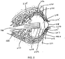
- FIG. 1 illustrates a section through the eyeball.
- the neuroretina 150 comprises multiple layers of cells and structures (see FIG. 2 ).
- the photoreceptor components of the retina are situated within the neuroretina which covers the internal posterior cavity of the eye, terminating anteriorly at the ora serrata 167.
- the ciliary body 168 and the iris 162 are covered by extensions of the retina, lacking photoreceptor components.
- the outermost layers of the eye consist of the sclera 164 and cornea 158.
- the sclera is pierced by the emerging optic nerve 166.
- the lens 160 and vitreous cavity 154 are also indicated.
- the macula 169 of the retina is typically a 3 mm by 5 mm oval region, at the center of which is the fovea 170.
- the layers of the eye at the posterior pole from inside to outside are shown in FIG. 2 : internal limiting membrane 40, nerve fiber layer 42, ganglion cell layer 44, inner plexiform 46, inner nuclear layer 48, outer plexiform 50, outer nuclear cell layer 52, and photoreceptor outer and inner segment layer 54, all of which constitute the anatomical inner retinal layer, also known as the neuroretina 56.
- the retinal pigment epithelium 58 and Bruch's membrane 60 constitute the outer retinal layer 62.
- the choriocapillaris 64 and choroid 66 comprise the choroidal vasculature 68.
- the outer coat of the eye is the sclera 70.
- Light 156 enters the retina as shown.
- electrical stimulus may be applied to the neuroretina in an indirect fashion, i.e., via one or more intervening biological structures.
- FIGs. 3-5 are schematic illustrations of such prior art techniques.
- FIG. 3 illustrates a technique (described in U.S. Patent No. 5,147,284 issued to Fedorov et al. ; hereinafter "Fedorov") in which electrical stimulation is applied to an eye 204 of a patient 202 via a pair of surgically implanted electrodes 210, 212 applied to surfaces of the eye 204 and optic nerve 206.
- a source of electrical stimulation 208 is provided coupled to the pair of electrodes 210, 212.
- the source 208 comprises an induction coil that provides electrical currents as a result of magnetic fields applied to the temporal region of the patient 202.
- FIG. 4 illustrates a more recent technique proposed by Chow in U.S. Patent No. 6,427,087 .
- an electrode 210' is placed in contact with tissues of the eye 204, whereas another electrode 212' is placed within the vitreous cavity 205 that may be in contact with the internal limiting membrane (see also the vitreous cavity 154 illustrated in FIG. 1 ). It is believed that the resulting trans-retinal stimulation resulting from this configuration will result in more efficient stimulation.
- the present invention encompasses indirect stimulation techniques based on application of one or more electrodes to surface structures of the eye, as opposed to peripheral structures such as the optic nerve or eyelids.
- surface structures of the eye may be divided into two classes, internal surface structures and external surface structures as described in greater detail below.
- surface structures of the eye may be defined as any of several laminae (beginning most interiorly with the sclera in the case of internal surface structures) and forming or surrounding the eye, depending upon the specific region of the eye under consideration.
- FIG. 6 A schematic illustration of an embodiment of indirect stimulation in accordance with the present invention is presented in FIG. 6 .
- at least one active or stimulating electrode 226 is applied to a surface structure of an eye 220.
- the at least one active electrode 226 is configured for chronic contact with the surface structure of the eye 220.
- chronic encompasses not only continuous periods of time but also repetitive and/or periodic intervals of time.
- the at least one active electrode 226 may be substantially permanently attached or otherwise coupled to the surface structure, or it may be configured to allow for repetitive placement in contact with, and subsequent removal from, the surface structure over a period of time established by a course of treatment.
- At least one return or ground electrode 228 is configured for application to tissues 222 of an external surface structure of the eyeball or to an internal surface structure of the eyeball being an outer surface of the sclera of the patient. Additionally, the at least one return electrode 228 may be configured for chronic or temporary application to the tissue 222.
- the at least one return electrode 228 may comprise one or more implantable electrodes substantially permanently coupled to the tissue 222 or it may comprise one or more temporary cutaneous electrodes secured with an adhesive and electrically coupled using a suitable conductive gel.
- the active and ground return electrodes establish a trans-retinal circuit such that application of an electrical stimulation signal to the active electrode will result in beneficial trans-retinal currents.
- the above system illustrated in FIG.6 also comprises a source of the electrical stimulation signal.
- the particular configuration of the source depends on internal and external implementation, relative to the patient.
- the source may comprise one or more input terminals 224 for application of the electrical stimulation signal to the electrodes.
- the electrical stimulation signal is provided by an extraocular signal source 224'.
- the electrical stimulation signal provided by the source may comprise virtually any type of waveform demonstrating a beneficial effect.
- the electrical stimulation signal may comprise an anodic or cathodic direct current signal or a time-varying waveform such as a square, sine, triangular, saw tooth signal or any other similar waveform.
- the electrical stimulation signal comprises a bi-phasic waveform that is balanced in the sense a net zero charge is applied to the retina over a period of time.
- Pulse frequencies may range anywhere from 10KHz down to 0.001 Hz or, in the extreme, even a continuous monophasic waveform, i.e., 0 Hz.
- the upper and lower eyelids 246, 247 enclose and protect the anterior portion of the eyeball.
- the conjunctiva comprises the bulbar conjunctiva 159' overlying the anterior portion of the sclera and the palpebral conjunctiva 159" overlying the inner surface of the upper and lower eyelids 246, 247.
- the fold between the bulbar and palpebral conjunctiva 159', 159" gives rise to a conjunctival fornix 250.
- external surface structures comprise those surface structures that are accessible via the palpebral fissure defined by the eyelids, i.e., the cornea 158 and the conjunctiva 159.
- Internal surface structures are defined as those surface structures posterior to the bulbar conjunctiva 159' and comprise the various laminae beginning with the sclera and its overlying structures, which overlying structures are dependent upon the particular region of the eyeball under consideration.
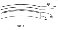
- the at least one corneal electrode 266 may comprise a plurality of discrete electrodes arranged, for example, in a ring formation affixed in proximity to the periphery of the supporting body 265, or may comprise a single annular electrode similarly affixed to the supporting body 265. Alternatively, the at least one corneal electrode 266 may be arranged closer to the central region of the cornea. Note that, for ease of illustration, none of FIGs. 10-12 illustrate the complementary electrode, nor do FIGs. 10-14 illustrate the electrical connections between the electrodes and the source of the electrical stimulation signal, which connections will be readily devisable as a matter of design choice by those having ordinary skill in the art.
- FIG. 11 illustrates another embodiment in which an annular supporting body 270 provides support for at least one epi-conjunctival electrode 271.
- the at least one epi-conjunctival electrode 271 may comprise a plurality of individually selectable electrodes or a single annular electrode as a matter of design choice.
- the at least one epi-conjunctival electrode 271 contacts the bulbar conjunctiva 159' in close proximity to the cornea 158.
- the at least one epi-conjunctival electrode 271 may be placed more distally from the cornea 158 and yet still in contact with the bulbar conjunctiva 159'.
- FIG. 12 illustrates yet another embodiment in which an electrode 275 is placed in epi-conjunctival contact within the conjunctival fornix 250.
- the electrode 275 may comprise a fibrous or filamentary electrode such as a "DTL" electrode. DTL electrodes are particularly advantageous because they are known to be well tolerated by patients given their relatively slender dimensions.
- a single electrode is illustrated in the lower conjunctival fornix 250, an electrode may also be placed in the upper conjunctival fornix as an alternative, or in addition to, the lower electrode.
- more than one electrode can be placed into either of the fornices at a single time.
- FIGs. 10-12 illustrates embodiments in which second electrodes are placed in contact with external surface structures of the eye.
- FIG. 13 schematically illustrates an embodiment in which electrodes are applied to internal surface structures.
- one or more supporting rings 281-283 are implanted in contact with internal surface structures.
- the third ring 283 is placed in contact with a substantially anterior portion of the eye, it is implanted beneath the bulbar conjunctiva 159'.
- a hybrid internal/external surface structure technique may be possible if the third ring 283 were placed above the bulbar conjunctiva 159' in a manner similar to that illustrated in FIG. 11 .
- each ring may be sutured in place in accordance with such techniques.
- the first and second rings 281, 282 are preferably placed beneath the extraocular muscles 236, 238, 240 in accordance with known techniques.
- Each ring comprises at least one electrode 285 and, in a preferred embodiment, each ring comprises a plurality of electrodes. Suitable materials for fabricating the supporting rings and electrodes are known to those having ordinary skill in the art. Preferably, each electrode is individually selectable. Additionally, each individual electrode may be electrically configured to act as an active electrode or a return electrode. In this manner, each ring 281-283 may comprise both active and return electrodes. In such an embodiment, it may be preferable to interleave active and return electrodes and, further, to antipodally arrange the active and return electrodes.
- each electrode in an antipodal electrode pair could be periodically switched between active and return operation.
- electrodes between rings could be activated as stimulating pairs, e.g., an electrode from a first ring 281 could be operated as an active electrode and an electrode from a second ring 282 could be operated as a return electrode, and vice versa.
- a specific number of supporting rings 281-283 positioned in substantially vertical orientations are illustrated in FIG. 13 , it is understood that a greater or lesser number of such rings could be employed and, further, that the orientation of such rings need not be limited to substantially vertical.
- the supporting rings 281-283 could be eliminated and, instead, each electrode 285 may comprise a separate, independent supporting member such that individual electrodes may be implanted at specific locations on specific internal surface structures.
- FIG. 14 Yet another embodiment providing contact with internal surface structures is illustrated in FIG. 14 .
- one or more supporting sheaths 290 comprising a plurality of electrodes 292 are positioned and secured in contact with internal surface structures of the eye.
- the discussion above with regard to individually selectable and antipodal electrodes relative to FIG. 13 equally applies to the arrangement of FIG. 14 .
- openings 294 may be provided. In the example illustrated in FIG.
- a plurality of sheaths 290 are provided such that each sheath 290 covers the surfaces between adjacent muscles with the openings 294 thereby being formed by the adjacency of the sheaths 290 when implanted.
- the anterior portion of the opening 294 could be fabricated such that a unitary body is provided (illustrated with dotted lines) whereas the opening of the posterior portion of the opening 294 would allow flexing of the sheath 290 for placement underneath the muscle.
- holes could be provided within the otherwise continuous sheaths 290.
- the muscles would need to be severed first to allow positioning of the sheaths, followed by reattachment of the muscles at positions corresponding to the holes.
- the embodiment illustrated in FIG. 14 allows multiple electrodes to be placed in contact with internal surface structures of the eye to facilitate indirect stimulation of the retina.
- FIGs. 13 and 14 are particular examples of the schema illustrated in FIG. 15 . Similar to the schemas illustrated in FIGs. 6 and 7 , the schema of FIG. 15 comprises a source 224, 224', 224" coupled to electrodes 226, 228 in contact with an eye 220. However, in this schema, the electrodes are both in contact with internal surface structures 300, 302 of the eye. In a presently preferred embodiment, the electrodes 226, 228, being configured for contact with internal surface structures, are preferably configured for chronic implantation, e.g., constructed of materials exhibiting very good biodurability, biocompatibility, etc.
- the electrodes 226, 228 may each comprise a plurality of separately selectable electrodes each of which may be alternated between stimulating and return electrode functionality.
- Particular implementations of the schemas of FIGs. 15 and 16 are further illustrated in FIGs. 17-19 .
- each of FIGs. 17-19 illustrate a top view of an eyeball comprising a cornea 158, conjunctiva 159, sclera 164 and, in hidden view, a neuroretina 150, macula 169 and optic nerve 166.
- FIG. 17 illustrates the placement of a first electrode 310 (in this case, a plurality of electrodes) placed on a first internal surface structure and a second electrode 320 on a second internal surface structure. Connections to an electrical source 324 are schematically shown.
- the first and second internal surface structures may comprise, for example, separate regions of scleral tissue.
- the plurality of electrodes 310 constituting the first electrode is supported by a body member 322 in the form of a scleral band or ring, as described previously with reference to FIG. 13 .
- the second electrode 320 although illustrated as a single electrode, may comprise a plurality of electrodes.
- the second electrode 320 may include a supporting body member (not shown) to aid in positioning and fixation of the second electrode. Applying an electrical stimulation signal across the first and second electrodes will result in trans-retinal currents that stimulate the retina. To maximize the effects of trans-retinal current, the second electrode 320 is preferably configured for and positioned upon an internal surface structure corresponding to (i.e., aligned with) the macula 169 of the eye.
- FIG. 18 illustrates placement of a second electrode 320 (as described above relative to FIG. 17 ) on an internal surface structure of the eye.
- the first electrode 330 is configured for epi-conjunctival placement, i.e., in contact with an external surface structure.
- the first electrode may comprise a supporting body member 332 as described previously with reference to FIG. 11 .
- FIG. 19 illustrates yet another internal/external surface structure embodiment combining a scleral ring electrode 310 implementation and an epi-conjunctival electrode 330 implementation.
Landscapes
- Health & Medical Sciences (AREA)
- Life Sciences & Earth Sciences (AREA)
- Engineering & Computer Science (AREA)
- Veterinary Medicine (AREA)
- Public Health (AREA)
- Biomedical Technology (AREA)
- General Health & Medical Sciences (AREA)
- Animal Behavior & Ethology (AREA)
- Ophthalmology & Optometry (AREA)
- Radiology & Medical Imaging (AREA)
- Nuclear Medicine, Radiotherapy & Molecular Imaging (AREA)
- Heart & Thoracic Surgery (AREA)
- Cardiology (AREA)
- Vascular Medicine (AREA)
- Cell Biology (AREA)
- Orthopedic Medicine & Surgery (AREA)
- Prostheses (AREA)
- Electrotherapy Devices (AREA)
Claims (9)
- Dispositif de traitement de maladie rétinienne dégénérative comprenant :une source (224, 224', 224") de stimulation électrique ;une première électrode (226) couplée à la source (224, 224', 224"), configurée pour être en contact avec une première structure superficielle interne (300) d'un globe oculaire (220), postérieure à la conjonctive bulbaire et comprenant les différentes membranes commençant par la sclérotique en tant que structure superficielle la plus intérieure et ses structures sus-jacentes,une seconde électrode (228) couplée à la source (224, 224', 224"), configurée pour être en contact avec une seconde structure superficielle du globe oculaire (220) ;caractérisé en ce que la source (224) comprend un composant de source interne (224') présentant une bobine d'induction réceptrice implantée de manière sous-cutanée et comprend en outre un composant de source externe (224") présentant une bobine d'induction émettrice configurée pour transmettre de l'énergie et des données, dans lequel la seconde électrode (228) est configurée pour être en contact avec une structure superficielle externe (158, 159, 304) du globe oculaire, ou en ce que la seconde électrode (228) est configurée pour être fixée à une structure superficielle interne du globe oculaire correspondant à une surface externe de la sclère.
- Dispositif selon la revendication 1, dans lequel la seconde électrode (228) est supportée sur un élément de corps (281-283, 290) configuré pour être fixé à la surface externe de la sclère.
- Dispositif selon la revendication 2, dans lequel l'élément de corps (281-283, 290) comprend une bande, un anneau ou une gaine qui est configuré(e) pour s'étendre au moins partiellement autour du globe oculaire pour faciliter le positionnement et la fixation de la seconde électrode.
- Dispositif selon la revendication 3, dans lequel l'élément de corps (281-283, 290) comprend une ou plusieurs ouvertures pour s'adapter à la présence de structures oculaires, telles que des liaisons entre des muscles et la sclère.
- Dispositif selon la revendication 1, dans lequel la première électrode (226) est au moins une électrode de stimulation configurée pour être en contact chronique avec la première structure superficielle du globe oculaire, et la seconde électrode (228) est au moins une électrode de référence configurée pour être en contact chronique avec la seconde structure superficielle du globe oculaire.
- Dispositif selon la revendication 5, dans lequel un signal de stimulation électrique provenant de la source (224, 224', 224") est appliqué au globe oculaire (220) par le biais de l'au moins une électrode de stimulation et de l'au moins une électrode de référence.
- Dispositif selon l'une quelconque des revendications précédentes, dans lequel la première électrode (226) est supportée sur un élément de corps configuré pour être en contact avec une structure superficielle interne correspondant à et en alignement avec une macula du globe oculaire.
- Dispositif selon la revendication 1, dans lequel la seconde électrode (228) est supportée sur un élément de corps (265, 270) configuré pour être en contact avec une structure superficielle externe (158, 159, 304) du globe oculaire, en particulier pour être en contact cornéen ou épi-conjonctival avec la structure superficielle externe du globe oculaire.
- Dispositif selon l'une quelconque des revendications précédentes, dans lequel la première électrode (226) et la seconde électrode (228) sont interconnectées électriquement par le biais d'un fil.
Applications Claiming Priority (3)
| Application Number | Priority Date | Filing Date | Title |
|---|---|---|---|
| US10/606,117 US20040106965A1 (en) | 2001-06-29 | 2003-06-24 | Methods and apparatus for treatment of degenerative retinal disease via indirect electrical stimulation |
| US10/863,519 US20050004625A1 (en) | 2001-06-29 | 2004-06-09 | Treatment of degenerative retinal disease via electrical stimulation of surface structures |
| PCT/US2004/018606 WO2005004985A2 (fr) | 2003-06-24 | 2004-06-10 | Traitement de maladies retiniennes par stimulation des structures superficielles |
Publications (3)
| Publication Number | Publication Date |
|---|---|
| EP1635906A2 EP1635906A2 (fr) | 2006-03-22 |
| EP1635906B1 EP1635906B1 (fr) | 2012-03-28 |
| EP1635906B2 true EP1635906B2 (fr) | 2019-02-20 |
Family
ID=34068494
Family Applications (1)
| Application Number | Title | Priority Date | Filing Date |
|---|---|---|---|
| EP04755009.0A Expired - Lifetime EP1635906B2 (fr) | 2003-06-24 | 2004-06-10 | Traitement de maladies retiniennes par stimulation des structures superficielles |
Country Status (7)
| Country | Link |
|---|---|
| US (1) | US20050004625A1 (fr) |
| EP (1) | EP1635906B2 (fr) |
| JP (1) | JP4654182B2 (fr) |
| AU (1) | AU2004255156C1 (fr) |
| CA (1) | CA2530171C (fr) |
| ES (1) | ES2385809T5 (fr) |
| WO (1) | WO2005004985A2 (fr) |
Families Citing this family (50)
| Publication number | Priority date | Publication date | Assignee | Title |
|---|---|---|---|---|
| US20050004625A1 (en) † | 2001-06-29 | 2005-01-06 | Chow Alan Y. | Treatment of degenerative retinal disease via electrical stimulation of surface structures |
| US20050033202A1 (en) * | 2001-06-29 | 2005-02-10 | Chow Alan Y. | Mechanically activated objects for treatment of degenerative retinal disease |
| US20080077192A1 (en) * | 2002-05-03 | 2008-03-27 | Afferent Corporation | System and method for neuro-stimulation |
| JP4204066B2 (ja) * | 2002-12-05 | 2009-01-07 | 保雄 田野 | 人工視覚システム |
| WO2005077452A1 (fr) * | 2004-02-06 | 2005-08-25 | Scyfix Llc | Traitement de troubles de la vision au moyen d'energie electrique, lumineuse et/ou sonore |
| AU2004226908B2 (en) * | 2004-11-02 | 2006-09-14 | Sydney Biotech Pty Ltd | Extraocular device |
| EP1652552B1 (fr) * | 2004-11-02 | 2008-09-17 | Sydney Biotech Pty. Ltd. | Dispositif extraoculaire |
| EP1879649B1 (fr) * | 2005-04-28 | 2013-05-15 | Second Sight Medical Products, Inc. | Boitier conçu pour un dispositif de stimulation neuronale implantable |
| US8562660B2 (en) | 2005-08-05 | 2013-10-22 | Gholam A. Peyman | Methods to regulate polarization and enhance function of excitable cells |
| US8460351B2 (en) | 2005-08-05 | 2013-06-11 | Gholam A. Peyman | Methods to regulate polarization and enhance function of excitable cells |
| US9962558B2 (en) | 2005-08-05 | 2018-05-08 | Gholam A. Peyman | Methods to regulate polarization and enhance function of cells |
| US8409263B2 (en) * | 2005-08-05 | 2013-04-02 | Gholam A. Peyman | Methods to regulate polarization of excitable cells |
| US10022457B2 (en) | 2005-08-05 | 2018-07-17 | Gholam A. Peyman | Methods to regulate polarization and enhance function of cells |
| EP2030210A4 (fr) | 2006-04-12 | 2010-04-14 | Proteus Biomedical Inc | Structures hermétiques implantables sans vide |
| WO2009006636A2 (fr) * | 2007-07-05 | 2009-01-08 | Second Sight Medical Products | Electrode de retour pour un ré seau d'électrodes de circuit flexible |
| JP5284014B2 (ja) * | 2008-09-02 | 2013-09-11 | 株式会社ニデック | 視覚再生補助装置 |
| US20100241060A1 (en) * | 2009-03-18 | 2010-09-23 | Roizman Keith | Surgical devices and methods |
| US20120083861A1 (en) * | 2010-10-04 | 2012-04-05 | The General Hospital Corporation | Selective activation of neurons by sinusoidal electric stimulation |
| US9821159B2 (en) | 2010-11-16 | 2017-11-21 | The Board Of Trustees Of The Leland Stanford Junior University | Stimulation devices and methods |
| CN103313754B (zh) | 2010-11-16 | 2015-09-30 | 小利兰·斯坦福大学理事会 | 用于治疗干眼的系统和方法 |
| EP2686062A4 (fr) * | 2011-03-18 | 2014-09-10 | Salk Inst For Biological Studi | Procédé pour identifier des types de cellules rétiniennes à l'aide de propriétés intrinsèques |
| EP2866885A1 (fr) * | 2012-06-29 | 2015-05-06 | Johnson & Johnson Vision Care, Inc. | Procédé et dispositif ophtalmique de cicatrisation galvanique d'un il |
| WO2014165124A1 (fr) | 2013-03-12 | 2014-10-09 | Oculeve, Inc. | Dispositifs, systèmes et procédés de pose d'implant |
| NZ704579A (en) | 2013-04-19 | 2018-10-26 | Oculeve Inc | Nasal stimulation devices and methods |
| WO2014193990A1 (fr) | 2013-05-28 | 2014-12-04 | Eduardo-Jose Chichilnisky | Prothèse intelligente destinée à faciliter la vision artificielle à l'aide d'abstraction de scène |
| EP3689338A1 (fr) | 2014-02-25 | 2020-08-05 | Oculeve, Inc. | Formulations polymères pour stimulation nasolacrimale |
| AU2015292278B2 (en) | 2014-07-25 | 2020-04-09 | Oculeve, Inc. | Stimulation patterns for treating dry eye |
| WO2016065211A1 (fr) * | 2014-10-22 | 2016-04-28 | Oculeve, Inc. | Lentille de contact permettant une augmentation de la production de larmes |
| WO2016065215A1 (fr) | 2014-10-22 | 2016-04-28 | Oculeve, Inc. | Dispositifs de stimulation et procédés de traitement de la sécheresse oculaire |
| WO2017066620A1 (fr) * | 2015-10-16 | 2017-04-20 | Rynerson James M | Dispositif energetique pour le traitement d'un trouble oculaire |
| US10426958B2 (en) | 2015-12-04 | 2019-10-01 | Oculeve, Inc. | Intranasal stimulation for enhanced release of ocular mucins and other tear proteins |
| US9849092B2 (en) | 2015-12-21 | 2017-12-26 | Gholam A. Peyman | Early cancer detection and enhanced immunotherapy |
| US10136820B2 (en) | 2015-12-21 | 2018-11-27 | Gholam A. Peyman | Method to visualize very early stage neoplasm or other lesions |
| US11433260B2 (en) | 2015-12-21 | 2022-09-06 | Gholam A. Peyman | Cancer treatment methods using thermotherapy and/or enhanced immunotherapy |
| US11660229B2 (en) | 2015-12-21 | 2023-05-30 | Gholam A. Peyman | Cancer treatment methods using thermotherapy and/or enhanced immunotherapy |
| US10300121B2 (en) | 2015-12-21 | 2019-05-28 | Gholam A. Peyman | Early cancer detection and enhanced immunotherapy |
| US11090385B2 (en) | 2015-12-21 | 2021-08-17 | Gholam A. Peyman | Early cancer detection and enhanced immunotherapy |
| US10252048B2 (en) | 2016-02-19 | 2019-04-09 | Oculeve, Inc. | Nasal stimulation for rhinitis, nasal congestion, and ocular allergies |
| US11419543B1 (en) | 2016-03-03 | 2022-08-23 | Gholam A. Peyman | Early disease detection and therapy |
| US10376600B2 (en) | 2016-03-03 | 2019-08-13 | Gholam A. Peyman | Early disease detection and therapy |
| US11007367B2 (en) * | 2016-03-16 | 2021-05-18 | Nova Oculus Canada Manufacturing Ulc | Microcurrent device for the treatment of visual disease |
| US10918864B2 (en) | 2016-05-02 | 2021-02-16 | Oculeve, Inc. | Intranasal stimulation for treatment of meibomian gland disease and blepharitis |
| RU2019118600A (ru) | 2016-12-02 | 2021-01-11 | Окулив, Инк. | Аппарат и способ составления прогноза синдрома сухого глаза и рекомендаций по лечению |
| US10456579B2 (en) | 2017-05-02 | 2019-10-29 | Nova Oculus Canada Manufacturing Ulc | Direct electrical stimulation delivery system for the treatment of visual disease |
| AU2019352954B2 (en) | 2018-10-01 | 2022-03-10 | Biovisics Medical, Inc. | System and methods for controlled electrical modulation for vision therapy |
| WO2020112980A2 (fr) | 2018-11-30 | 2020-06-04 | Biovisics Medical, Llc | Appareils de thérapie visuelle portés sur la tête |
| EP3952979A1 (fr) | 2019-04-10 | 2022-02-16 | Biovisics Medical, Inc. | Systèmes et interfaces de thérapie oculaire |
| US11511112B2 (en) | 2019-06-14 | 2022-11-29 | Biovisics Medical, Inc. | Wearable medical device |
| WO2021011255A1 (fr) | 2019-07-12 | 2021-01-21 | Biovisics Medical, Inc. | Modes et systèmes de thérapie oculaire |
| US11998765B2 (en) | 2020-09-29 | 2024-06-04 | Cancer Rx, LLC | Cancer imaging methods and cancer treatment methods using thermotherapy and drug delivery |
Citations (8)
| Publication number | Priority date | Publication date | Assignee | Title |
|---|---|---|---|---|
| EP0325201A2 (fr) † | 1988-01-20 | 1989-07-26 | Etama Ag | Stimulateur pour améliorer la vue des amblyopes |
| US4955378A (en) † | 1988-05-02 | 1990-09-11 | University Of South Florida | Apparatus and methods for performing electrofusion at specific anatomical sites |
| EP0723984A1 (fr) † | 1995-01-26 | 1996-07-31 | Cheil Synthetics Inc. | Copolyestre biodégradable et procédé pour sa préparation |
| WO1999045870A1 (fr) † | 1998-03-13 | 1999-09-16 | Johns Hopkins University | Prothese visuelle |
| WO2001083026A1 (fr) † | 2000-05-04 | 2001-11-08 | Optobionics Corporation | Prothese retinienne artificielle a electrodes de stimulation et de retour de masse disposees de part et d'autre de la neuroretine, et son procede d'implantation |
| WO2003002070A2 (fr) † | 2001-06-29 | 2003-01-09 | Optobionics Corporation | Stimulation physique et/ou mecanique permettant d'ameliorer les fonctions de cellules retiniennes endommagees |
| US20040106965A1 (en) † | 2001-06-29 | 2004-06-03 | Chow Alan Y. | Methods and apparatus for treatment of degenerative retinal disease via indirect electrical stimulation |
| US20050004625A1 (en) † | 2001-06-29 | 2005-01-06 | Chow Alan Y. | Treatment of degenerative retinal disease via electrical stimulation of surface structures |
Family Cites Families (96)
| Publication number | Priority date | Publication date | Assignee | Title |
|---|---|---|---|---|
| US793004A (en) * | 1904-07-23 | 1905-06-20 | Frank Howard May | Eye-massage machine. |
| US1684860A (en) * | 1927-03-12 | 1928-09-18 | De Forest B Catlin | Eye-treating apparatus |
| US2525381A (en) * | 1947-09-25 | 1950-10-10 | Tower Paul | Contact-type electrode holder |
| US2721316A (en) * | 1953-06-09 | 1955-10-18 | Joseph D Shaw | Method and means for aiding the blind |
| US2760483A (en) * | 1953-10-29 | 1956-08-28 | Tassicker Graham Edward | Retinal stimulator |
| US3320947A (en) * | 1963-10-25 | 1967-05-23 | Knoll Max Hans | Device for the excitation of nerve networks |
| US3594823A (en) * | 1969-02-11 | 1971-07-27 | Patent Management Inc | Visual substitution system with receptor scanning means |
| US3628193A (en) * | 1969-02-19 | 1971-12-21 | Inst Of Medical Sciences The | Tactile image projection system |
| GB1319774A (en) * | 1969-06-26 | 1973-06-06 | Nat Res Dev | Visual prosthetic device |
| US3995635A (en) * | 1971-09-09 | 1976-12-07 | Alza Corporation | Ocular insert |
| US3766311A (en) * | 1972-04-26 | 1973-10-16 | H Boll | Sensory substitution system |
| US3769961A (en) * | 1972-07-20 | 1973-11-06 | I Fatt | Conjunctival device |
| US3893444A (en) * | 1972-07-20 | 1975-07-08 | Univ California | Non-invasively measuring arterial oxygen tension |
| US3848608A (en) * | 1973-07-23 | 1974-11-19 | Gen Electric | Subject integument spatial stimulator |
| US3998659A (en) * | 1974-01-28 | 1976-12-21 | Texas Instruments Incorporated | Solar cell with semiconductor particles and method of fabrication |
| US3914800A (en) * | 1974-06-06 | 1975-10-28 | Inst Of Medical Sciences | Fluid mechanical tactile oscilloscope to augment the five senses |
| US4001867A (en) * | 1974-08-22 | 1977-01-04 | Dionics, Inc. | Semiconductive devices with integrated circuit switches |
| US4018218A (en) * | 1975-03-12 | 1977-04-19 | Carlson James E | Method and apparatus for sleep induction |
| US4089329A (en) * | 1976-03-18 | 1978-05-16 | University Of Utah Research Institute | Noninvasive, continuous intraocular pressure monitor |
| FR2379085A1 (fr) * | 1977-01-31 | 1978-08-25 | Comp Generale Electricite | Obturateur electro-optique ultrarapide |
| US4326529A (en) * | 1978-05-26 | 1982-04-27 | The United States Of America As Represented By The United States Department Of Energy | Corneal-shaping electrode |
| US4251887A (en) * | 1979-04-02 | 1981-02-24 | Anis Aziz Y | Posterior chamber capsular lens implant and method for implantation of the lens |
| US4272910A (en) * | 1979-07-31 | 1981-06-16 | Danz W R | Ocular prosthetic or the like |
| US4271841A (en) * | 1980-01-31 | 1981-06-09 | Medtronic, Inc. | Electro-ocular stimulation system |
| US4484922A (en) * | 1981-06-25 | 1984-11-27 | Rosenwald Peter L | Occular device |
| US4551149A (en) * | 1982-02-16 | 1985-11-05 | Michael Sciarra | Prosthetic vision system |
| US4600004A (en) * | 1982-09-08 | 1986-07-15 | Osvaldo Lopez | Intraocular lens holder and inserter |
| US4524776A (en) * | 1983-10-27 | 1985-06-25 | Withers Stanley J | Split carrier for eyelid sensor and the like |
| US4614193A (en) * | 1984-01-09 | 1986-09-30 | Pain Suppression Labs, Inc. | Electronic glaucoma treatment apparatus and methodology |
| US4601545A (en) * | 1984-05-16 | 1986-07-22 | Kern Seymour P | Variable power lens system |
| US4664117A (en) * | 1984-10-09 | 1987-05-12 | Beck Stephen C | Apparatus and method for generating phosphenes |
| US4603697A (en) * | 1985-01-07 | 1986-08-05 | William Kamerling | System for preventing or treating open angle glaucoma and presbyopia |
| GB8513192D0 (en) * | 1985-05-24 | 1985-06-26 | British Telecomm | Optical logic devices |
| US4667676A (en) * | 1985-06-17 | 1987-05-26 | Audimax, Inc. | Method of evaluating the vestibular system |
| US4628933A (en) * | 1985-07-23 | 1986-12-16 | Michelson Robin P | Method and apparatus for visual prosthesis |
| US4750498A (en) * | 1986-02-21 | 1988-06-14 | Coopervision, Inc. | Method and tool for inserting an intraocular lens |
| US4679572A (en) * | 1986-03-11 | 1987-07-14 | Intermedics, Inc. | Low threshold cardiac pacing electrodes |
| JPS62179601U (fr) * | 1986-04-30 | 1987-11-14 | ||
| GB8612537D0 (en) * | 1986-05-22 | 1986-07-02 | Gen Foods Ltd | Containers |
| US4874237A (en) * | 1987-05-07 | 1989-10-17 | Lions Eye Inst. Of Western Australia | Electroretinogram apparatus |
| CH684971A5 (de) * | 1989-03-16 | 1995-02-15 | Landis & Gyr Tech Innovat | Ultraviolettlicht-Sensor. |
| US4989605A (en) * | 1989-03-31 | 1991-02-05 | Joel Rossen | Transcutaneous electrical nerve stimulation (TENS) device |
| US5107835A (en) * | 1989-05-22 | 1992-04-28 | Physiodynamics | Electrotherapeutic treatment |
| US5159927A (en) * | 1989-07-26 | 1992-11-03 | Ferdinand Schmid | Visual prosthesis apparatus and method |
| US5024223A (en) * | 1989-08-08 | 1991-06-18 | Chow Alan Y | Artificial retina device |
| US5016633A (en) * | 1989-08-08 | 1991-05-21 | Chow Alan Y | Artificial retina device |
| RU1799577C (ru) * | 1989-08-17 | 1993-03-07 | Межотраслевой научно-технический комплекс "Микрохирургия глаза" | Способ улучшени зрительных функций при заболевани х зрительного нерва и сетчатки и устройство дл его осуществлени |
| US5025811A (en) * | 1990-02-16 | 1991-06-25 | Dobrogowski Michael J | Method for focal destruction of eye tissue by electroablation |
| GB2243082B (en) * | 1990-04-20 | 1994-02-16 | Marko Hawlina | Electrode for electroretinography |
| US5099829A (en) * | 1990-04-25 | 1992-03-31 | Wu An Chuan | Massage device good for eyes |
| US5109844A (en) * | 1990-10-11 | 1992-05-05 | Duke University | Retinal microstimulation |
| US5130528A (en) * | 1991-03-01 | 1992-07-14 | International Business Machines Corporation | Opto-photo-electric switch |
| JPH04365382A (ja) * | 1991-06-13 | 1992-12-17 | Toshiba Corp | 半導体発光装置及びその駆動方法 |
| JP2974469B2 (ja) * | 1991-09-17 | 1999-11-10 | 株式会社東芝 | 信号伝送回路 |
| US5223728A (en) * | 1992-04-02 | 1993-06-29 | Motorola, Inc. | Optical switch integrated circuit |
| US5351309A (en) * | 1992-06-30 | 1994-09-27 | National Science Council | Image edge sensor |
| US5519205A (en) * | 1992-09-30 | 1996-05-21 | Lsi Logic Corporation | Color electronic camera including photosensor array having binary diffractive lens elements |
| US5338991A (en) * | 1992-12-28 | 1994-08-16 | Lu Chao Cheng | High power solid state relay with input presence and polarity indication |
| US5360438A (en) * | 1993-01-26 | 1994-11-01 | Fisher Mary R | Method and device for improving cranial nerve function to improve muscle function and thereby overcome visual/perceptual dysfunction |
| US5556423A (en) * | 1993-05-03 | 1996-09-17 | Alan Y. Chow | Independent photoelectric artificial retina device and method of using same |
| US5397350A (en) * | 1993-05-03 | 1995-03-14 | Chow; Alan Y. | Independent photoelectric artificial retina device and method of using same |
| US5411540A (en) * | 1993-06-03 | 1995-05-02 | Massachusetts Institute Of Technology | Method and apparatus for preferential neuron stimulation |
| US5578040A (en) * | 1994-06-14 | 1996-11-26 | Smith; Albert C. | Ocular repair system and apparatus |
| US5522864A (en) * | 1994-10-25 | 1996-06-04 | Wallace; Larry B. | Apparatus and method for ocular treatment |
| US5496355A (en) * | 1994-11-21 | 1996-03-05 | Lipsky; Stephen N. | Extraocular muscle sensor and stimulator |
| JPH08297465A (ja) * | 1995-04-26 | 1996-11-12 | Hiroshi Yamamoto | 視神経映像出力装置とその方法 |
| US5895415A (en) * | 1995-06-06 | 1999-04-20 | Optobionics Corporation | Multi-phasic microphotodiode retinal implant and adaptive imaging retinal stimulation system |
| EP1435255B1 (fr) * | 1995-06-06 | 2006-05-17 | Optobionics Corporation | Système de stimulation rétinienne par imagerie adaptative |
| DE19529371C3 (de) * | 1995-08-10 | 2003-05-28 | Nmi Univ Tuebingen | Mikroelektroden-Anordnung |
| US5717201A (en) * | 1996-04-18 | 1998-02-10 | National Science Council | Double four-quadrant angle-position detector |
| US5895414A (en) * | 1996-04-19 | 1999-04-20 | Sanchez-Zambrano; Sergio | Pacemaker housing |
| US6066675A (en) * | 1996-09-13 | 2000-05-23 | The Regents Of The University Of California | Method for treatment of retinal diseases |
| WO1998017344A1 (fr) * | 1996-10-23 | 1998-04-30 | Eberhard-Karls-Universität Tübingen Universitätsklinikum | Systeme de micro-electrodes a commande optique pour stimuler des cellules, notamment un implant retinien |
| DE19705988C2 (de) * | 1996-10-23 | 2002-04-11 | Univ Eberhard Karls | Retina-Implantat |
| US5837995A (en) * | 1996-11-25 | 1998-11-17 | Alan Y. Chow | Wavelength-controllable voltage-phase photodiode optoelectronic switch ("opsistor") |
| US5865839A (en) * | 1996-12-30 | 1999-02-02 | Doorish; John F. | Artificial retina |
| US5782894A (en) * | 1997-03-05 | 1998-07-21 | Israel; Ben | Device and method for improving ocular focusing at near vision points |
| US6458157B1 (en) * | 1997-08-04 | 2002-10-01 | Suaning Gregg Joergen | Retinal stimulator |
| US6083251A (en) * | 1997-11-13 | 2000-07-04 | Shindo; Kohei | Eye treatment method and apparatus |
| FR2773320B1 (fr) * | 1998-01-05 | 2000-03-03 | Optisinvest | Dispositif pour le transfert intraoculaire de produits actifs par iontophorese |
| US5944747A (en) * | 1998-03-13 | 1999-08-31 | Johns Hopkins University | Method for preferential outer retinal stimulation |
| US6324429B1 (en) * | 1998-05-08 | 2001-11-27 | Massachusetts Eye And Ear Infirmary | Chronically implantable retinal prosthesis |
| US6035236A (en) * | 1998-07-13 | 2000-03-07 | Bionergy Therapeutics, Inc. | Methods and apparatus for electrical microcurrent stimulation therapy |
| DE19838603A1 (de) * | 1998-08-25 | 2000-03-09 | Eldra Kunststofftechnik Gmbh | Dekorschicht für Airbagabdeckungen |
| US6101411A (en) * | 1998-09-24 | 2000-08-08 | Newsome; David A. | Dilation enhancer |
| US6282449B1 (en) * | 1998-10-21 | 2001-08-28 | William Kamerling | Method and device for causing the eye to focus on a near object |
| EP2275166A3 (fr) * | 1999-03-24 | 2014-05-21 | Second Sight Medical Products, Inc. | Prothèse visuelle |
| US6264971B1 (en) * | 1999-11-04 | 2001-07-24 | Btg International Limited | Ocular insert |
| US6389317B1 (en) * | 2000-03-31 | 2002-05-14 | Optobionics Corporation | Multi-phasic microphotodetector retinal implant with variable voltage and current capability |
| US6511508B1 (en) * | 2000-08-04 | 2003-01-28 | Environmental Robots, Inc. | Surgical correction of human eye refractive errors by active composite artificial muscle implants |
| US6647297B2 (en) * | 2000-08-09 | 2003-11-11 | The United States Of America As Represented By The Secretary Of The Navy | Permanent retinal implant device |
| US6393327B1 (en) * | 2000-08-09 | 2002-05-21 | The United States Of America As Represented By The Secretary Of The Navy | Microelectronic stimulator array |
| US7103416B2 (en) * | 2001-01-16 | 2006-09-05 | Second Sight Medical Products, Inc. | Visual prosthesis including enhanced receiving and stimulating portion |
| US7003355B1 (en) * | 2001-11-20 | 2006-02-21 | Suaning Gregg J | Vision prosthesis for the blind and method for implementing same |
| JP2003210513A (ja) * | 2002-01-23 | 2003-07-29 | Nidek Co Ltd | 眼科用治療装置 |
| DE10304831A1 (de) | 2003-01-31 | 2004-08-26 | Eberhard-Karls-Universität Tübingen Universitätsklinikum | Retina-Implantat zum Stimulieren einer Retina in Abhängigkeit von einfallendem Licht |
-
2004
- 2004-06-09 US US10/863,519 patent/US20050004625A1/en not_active Abandoned
- 2004-06-10 JP JP2006517228A patent/JP4654182B2/ja not_active Expired - Fee Related
- 2004-06-10 WO PCT/US2004/018606 patent/WO2005004985A2/fr active Application Filing
- 2004-06-10 CA CA2530171A patent/CA2530171C/fr not_active Expired - Fee Related
- 2004-06-10 AU AU2004255156A patent/AU2004255156C1/en not_active Ceased
- 2004-06-10 ES ES04755009T patent/ES2385809T5/es not_active Expired - Lifetime
- 2004-06-10 EP EP04755009.0A patent/EP1635906B2/fr not_active Expired - Lifetime
Patent Citations (9)
| Publication number | Priority date | Publication date | Assignee | Title |
|---|---|---|---|---|
| EP0325201A2 (fr) † | 1988-01-20 | 1989-07-26 | Etama Ag | Stimulateur pour améliorer la vue des amblyopes |
| US4955378A (en) † | 1988-05-02 | 1990-09-11 | University Of South Florida | Apparatus and methods for performing electrofusion at specific anatomical sites |
| EP0723984A1 (fr) † | 1995-01-26 | 1996-07-31 | Cheil Synthetics Inc. | Copolyestre biodégradable et procédé pour sa préparation |
| WO1999045870A1 (fr) † | 1998-03-13 | 1999-09-16 | Johns Hopkins University | Prothese visuelle |
| WO2001083026A1 (fr) † | 2000-05-04 | 2001-11-08 | Optobionics Corporation | Prothese retinienne artificielle a electrodes de stimulation et de retour de masse disposees de part et d'autre de la neuroretine, et son procede d'implantation |
| US6427087B1 (en) † | 2000-05-04 | 2002-07-30 | Optobionics Corporation | Artificial retina device with stimulating and ground return electrodes disposed on opposite sides of the neuroretina and method of attachment |
| WO2003002070A2 (fr) † | 2001-06-29 | 2003-01-09 | Optobionics Corporation | Stimulation physique et/ou mecanique permettant d'ameliorer les fonctions de cellules retiniennes endommagees |
| US20040106965A1 (en) † | 2001-06-29 | 2004-06-03 | Chow Alan Y. | Methods and apparatus for treatment of degenerative retinal disease via indirect electrical stimulation |
| US20050004625A1 (en) † | 2001-06-29 | 2005-01-06 | Chow Alan Y. | Treatment of degenerative retinal disease via electrical stimulation of surface structures |
Non-Patent Citations (2)
| Title |
|---|
| CHOW A.Y. ET AL: "THE ARTIFICIAL SILICON RETINA MICROCHIP FOR THE TREATMENT OF VISION LOSS FROM RETINITIS PIGMENTOSA.", ARCH OPHTHALMOL., vol. 122, no. 4, April 2004 (2004-04-01), pages 460 - 469 † |
| DECISION OF THE TECHNICAL BOARD OF APPEAL REGARDING EUROPEAN APPLICATION 02780956.5 † |
Also Published As
| Publication number | Publication date |
|---|---|
| CA2530171A1 (fr) | 2005-01-20 |
| EP1635906A2 (fr) | 2006-03-22 |
| US20050004625A1 (en) | 2005-01-06 |
| AU2004255156B2 (en) | 2010-09-16 |
| ES2385809T5 (es) | 2019-10-09 |
| EP1635906B1 (fr) | 2012-03-28 |
| AU2004255156C1 (en) | 2011-02-10 |
| AU2004255156A1 (en) | 2005-01-20 |
| JP4654182B2 (ja) | 2011-03-16 |
| CA2530171C (fr) | 2013-07-23 |
| JP2007521071A (ja) | 2007-08-02 |
| ES2385809T3 (es) | 2012-08-01 |
| WO2005004985A3 (fr) | 2005-03-31 |
| WO2005004985A2 (fr) | 2005-01-20 |
Similar Documents
| Publication | Publication Date | Title |
|---|---|---|
| EP1635906B2 (fr) | Traitement de maladies retiniennes par stimulation des structures superficielles | |
| US7031776B2 (en) | Methods for improving damaged retinal cell function | |
| US20040106965A1 (en) | Methods and apparatus for treatment of degenerative retinal disease via indirect electrical stimulation | |
| Sehic et al. | Electrical stimulation as a means for improving vision | |
| US7877148B2 (en) | Extraocular device | |
| AU2002352103A1 (en) | Methods for improving damaged retinal cell function | |
| Majji et al. | Long-term histological and electrophysiological results of an inactive epiretinal electrode array implantation in dogs | |
| O’Hearn et al. | Electrical stimulation in normal and retinal degeneration (rd1) isolated mouse retina | |
| WO2021238415A1 (fr) | Appareil d'implant et prothèse visuelle équipée de celui-ci | |
| Matthaei et al. | Progress in the development of vision prostheses | |
| US20060224212A1 (en) | Neural electrode array | |
| Chow | Retinal prostheses development in retinitis pigmentosa patients—progress and comparison | |
| Nakano et al. | Sinusoidal Electrical Pulse More Efficiently Evokes Retinal Excitation than Rectangular Electrical Pulse in Retinal Prostheses. | |
| Liang et al. | Threshold suprachoroidal-transretinal stimulation current required by different-size electrodes in rabbit eyes | |
| Banarji et al. | Visual prosthesis: Artificial vision | |
| WO2021238419A1 (fr) | Dispositif d'implantation et prothèse visuelle présentant un tel dispositif | |
| AU2004226908B2 (en) | Extraocular device | |
| Suaning | Strategic circuits for neuromodulation of the visual system | |
| Chow et al. | The semiconductor-based microphotodiode array artificial silicon retina | |
| Fujikado et al. | Artificial vision: vision of a newcomer | |
| Calle | Towards a High Resolution Retinal Implant | |
| Walter et al. | Experimental implantation of devices for electrical retinal stimulation in rabbits: preliminary results | |
| AU2002312620A1 (en) | Methods for improving damaged retinal cell function using physical and/or mechanical stimulation |
Legal Events
| Date | Code | Title | Description |
|---|---|---|---|
| PUAI | Public reference made under article 153(3) epc to a published international application that has entered the european phase |
Free format text: ORIGINAL CODE: 0009012 |
|
| 17P | Request for examination filed |
Effective date: 20051208 |
|
| AK | Designated contracting states |
Kind code of ref document: A2 Designated state(s): AT BE BG CH CY CZ DE DK EE ES FI FR GB GR HU IE IT LI LU MC NL PL PT RO SE SI SK TR |
|
| DAX | Request for extension of the european patent (deleted) | ||
| 17Q | First examination report despatched |
Effective date: 20080131 |
|
| RAP1 | Party data changed (applicant data changed or rights of an application transferred) |
Owner name: IMI INTELLIGENT MEDICAL IMPLANTS AG |
|
| GRAP | Despatch of communication of intention to grant a patent |
Free format text: ORIGINAL CODE: EPIDOSNIGR1 |
|
| RTI1 | Title (correction) |
Free format text: DEVICE FOR TREATMENT OF DEGENERATIVE RETINAL DISEASE VIA ELECTRICAL STIMULATION OF SURFACE STUCTURES OF THE EYEBALL |
|
| GRAS | Grant fee paid |
Free format text: ORIGINAL CODE: EPIDOSNIGR3 |
|
| GRAA | (expected) grant |
Free format text: ORIGINAL CODE: 0009210 |
|
| AK | Designated contracting states |
Kind code of ref document: B1 Designated state(s): AT BE BG CH CY CZ DE DK EE ES FI FR GB GR HU IE IT LI LU MC NL PL PT RO SE SI SK TR |
|
| REG | Reference to a national code |
Ref country code: GB Ref legal event code: FG4D |
|
| REG | Reference to a national code |
Ref country code: CH Ref legal event code: EP |
|
| REG | Reference to a national code |
Ref country code: AT Ref legal event code: REF Ref document number: 551094 Country of ref document: AT Kind code of ref document: T Effective date: 20120415 |
|
| REG | Reference to a national code |
Ref country code: IE Ref legal event code: FG4D |
|
| REG | Reference to a national code |
Ref country code: DE Ref legal event code: R096 Ref document number: 602004037115 Country of ref document: DE Effective date: 20120524 |
|
| REG | Reference to a national code |
Ref country code: NL Ref legal event code: T3 |
|
| REG | Reference to a national code |
Ref country code: CH Ref legal event code: NV Representative=s name: PATENTANWALTSKANZLEI NUECKEL |
|
| REG | Reference to a national code |
Ref country code: ES Ref legal event code: FG2A Ref document number: 2385809 Country of ref document: ES Kind code of ref document: T3 Effective date: 20120801 |
|
| PG25 | Lapsed in a contracting state [announced via postgrant information from national office to epo] |
Ref country code: GR Free format text: LAPSE BECAUSE OF FAILURE TO SUBMIT A TRANSLATION OF THE DESCRIPTION OR TO PAY THE FEE WITHIN THE PRESCRIBED TIME-LIMIT Effective date: 20120629 Ref country code: FI Free format text: LAPSE BECAUSE OF FAILURE TO SUBMIT A TRANSLATION OF THE DESCRIPTION OR TO PAY THE FEE WITHIN THE PRESCRIBED TIME-LIMIT Effective date: 20120328 |
|
| PG25 | Lapsed in a contracting state [announced via postgrant information from national office to epo] |
Ref country code: CY Free format text: LAPSE BECAUSE OF FAILURE TO SUBMIT A TRANSLATION OF THE DESCRIPTION OR TO PAY THE FEE WITHIN THE PRESCRIBED TIME-LIMIT Effective date: 20120328 |
|
| PG25 | Lapsed in a contracting state [announced via postgrant information from national office to epo] |
Ref country code: RO Free format text: LAPSE BECAUSE OF FAILURE TO SUBMIT A TRANSLATION OF THE DESCRIPTION OR TO PAY THE FEE WITHIN THE PRESCRIBED TIME-LIMIT Effective date: 20120328 Ref country code: BE Free format text: LAPSE BECAUSE OF FAILURE TO SUBMIT A TRANSLATION OF THE DESCRIPTION OR TO PAY THE FEE WITHIN THE PRESCRIBED TIME-LIMIT Effective date: 20120328 Ref country code: SI Free format text: LAPSE BECAUSE OF FAILURE TO SUBMIT A TRANSLATION OF THE DESCRIPTION OR TO PAY THE FEE WITHIN THE PRESCRIBED TIME-LIMIT Effective date: 20120328 Ref country code: CZ Free format text: LAPSE BECAUSE OF FAILURE TO SUBMIT A TRANSLATION OF THE DESCRIPTION OR TO PAY THE FEE WITHIN THE PRESCRIBED TIME-LIMIT Effective date: 20120328 Ref country code: SE Free format text: LAPSE BECAUSE OF FAILURE TO SUBMIT A TRANSLATION OF THE DESCRIPTION OR TO PAY THE FEE WITHIN THE PRESCRIBED TIME-LIMIT Effective date: 20120328 Ref country code: PL Free format text: LAPSE BECAUSE OF FAILURE TO SUBMIT A TRANSLATION OF THE DESCRIPTION OR TO PAY THE FEE WITHIN THE PRESCRIBED TIME-LIMIT Effective date: 20120328 Ref country code: EE Free format text: LAPSE BECAUSE OF FAILURE TO SUBMIT A TRANSLATION OF THE DESCRIPTION OR TO PAY THE FEE WITHIN THE PRESCRIBED TIME-LIMIT Effective date: 20120328 |
|
| PG25 | Lapsed in a contracting state [announced via postgrant information from national office to epo] |
Ref country code: SK Free format text: LAPSE BECAUSE OF FAILURE TO SUBMIT A TRANSLATION OF THE DESCRIPTION OR TO PAY THE FEE WITHIN THE PRESCRIBED TIME-LIMIT Effective date: 20120328 Ref country code: PT Free format text: LAPSE BECAUSE OF FAILURE TO SUBMIT A TRANSLATION OF THE DESCRIPTION OR TO PAY THE FEE WITHIN THE PRESCRIBED TIME-LIMIT Effective date: 20120730 |
|
| PLBI | Opposition filed |
Free format text: ORIGINAL CODE: 0009260 |
|
| 26 | Opposition filed |
Opponent name: RETINA IMPLANT AG Effective date: 20121208 |
|
| PG25 | Lapsed in a contracting state [announced via postgrant information from national office to epo] |
Ref country code: DK Free format text: LAPSE BECAUSE OF FAILURE TO SUBMIT A TRANSLATION OF THE DESCRIPTION OR TO PAY THE FEE WITHIN THE PRESCRIBED TIME-LIMIT Effective date: 20120328 Ref country code: MC Free format text: LAPSE BECAUSE OF NON-PAYMENT OF DUE FEES Effective date: 20120630 |
|
| PLAX | Notice of opposition and request to file observation + time limit sent |
Free format text: ORIGINAL CODE: EPIDOSNOBS2 |
|
| REG | Reference to a national code |
Ref country code: DE Ref legal event code: R026 Ref document number: 602004037115 Country of ref document: DE Effective date: 20121208 |
|
| REG | Reference to a national code |
Ref country code: IE Ref legal event code: MM4A |
|
| PG25 | Lapsed in a contracting state [announced via postgrant information from national office to epo] |
Ref country code: IE Free format text: LAPSE BECAUSE OF NON-PAYMENT OF DUE FEES Effective date: 20120610 |
|
| PLBB | Reply of patent proprietor to notice(s) of opposition received |
Free format text: ORIGINAL CODE: EPIDOSNOBS3 |
|
| PG25 | Lapsed in a contracting state [announced via postgrant information from national office to epo] |
Ref country code: BG Free format text: LAPSE BECAUSE OF FAILURE TO SUBMIT A TRANSLATION OF THE DESCRIPTION OR TO PAY THE FEE WITHIN THE PRESCRIBED TIME-LIMIT Effective date: 20120628 |
|
| REG | Reference to a national code |
Ref country code: CH Ref legal event code: PUE Owner name: PIXIUM VISION SA, FR Free format text: FORMER OWNER: IMI INTELLIGENT MEDICAL IMPLANTS AG, CH |
|
| REG | Reference to a national code |
Ref country code: DE Ref legal event code: R082 Ref document number: 602004037115 Country of ref document: DE Representative=s name: GRAF VON STOSCH PATENTANWALTSGESELLSCHAFT MBH, DE |
|
| REG | Reference to a national code |
Ref country code: ES Ref legal event code: PC2A Owner name: PIXIUM VISION SA Effective date: 20131204 |
|
| REG | Reference to a national code |
Ref country code: GB Ref legal event code: 732E Free format text: REGISTERED BETWEEN 20131205 AND 20131211 |
|
| REG | Reference to a national code |
Ref country code: DE Ref legal event code: R082 Ref document number: 602004037115 Country of ref document: DE Representative=s name: GRAF VON STOSCH PATENTANWALTSGESELLSCHAFT MBH, DE Effective date: 20131118 Ref country code: DE Ref legal event code: R081 Ref document number: 602004037115 Country of ref document: DE Owner name: PIXIUM VISION SA, FR Free format text: FORMER OWNER: IMI INTELLIGENT MEDICAL IMPLANTS AG, ZUG, CH Effective date: 20131118 Ref country code: DE Ref legal event code: R081 Ref document number: 602004037115 Country of ref document: DE Owner name: PIXIUM VISION SA, FR Free format text: FORMER OWNER: OPTOBIONICS CORP., NAPERVILLE, US Effective date: 20120329 Ref country code: DE Ref legal event code: R081 Ref document number: 602004037115 Country of ref document: DE Owner name: PIXIUM VISION SA, FR Free format text: FORMER OWNER: OPTOBIONICS CORP., NAPERVILLE, ILL., US Effective date: 20120329 |
|
| RAP2 | Party data changed (patent owner data changed or rights of a patent transferred) |
Owner name: PIXIUM VISION SA |
|
| REG | Reference to a national code |
Ref country code: FR Ref legal event code: TP Owner name: PIXIUM VISION SA, FR Effective date: 20140227 |
|
| PLAY | Examination report in opposition despatched + time limit |
Free format text: ORIGINAL CODE: EPIDOSNORE2 |
|
| PG25 | Lapsed in a contracting state [announced via postgrant information from national office to epo] |
Ref country code: TR Free format text: LAPSE BECAUSE OF FAILURE TO SUBMIT A TRANSLATION OF THE DESCRIPTION OR TO PAY THE FEE WITHIN THE PRESCRIBED TIME-LIMIT Effective date: 20120328 |
|
| PG25 | Lapsed in a contracting state [announced via postgrant information from national office to epo] |
Ref country code: LU Free format text: LAPSE BECAUSE OF NON-PAYMENT OF DUE FEES Effective date: 20120610 |
|
| PLBC | Reply to examination report in opposition received |
Free format text: ORIGINAL CODE: EPIDOSNORE3 |
|
| REG | Reference to a national code |
Ref country code: NL Ref legal event code: SD Effective date: 20140723 |
|
| PG25 | Lapsed in a contracting state [announced via postgrant information from national office to epo] |
Ref country code: HU Free format text: LAPSE BECAUSE OF FAILURE TO SUBMIT A TRANSLATION OF THE DESCRIPTION OR TO PAY THE FEE WITHIN THE PRESCRIBED TIME-LIMIT Effective date: 20040610 |
|
| PLAY | Examination report in opposition despatched + time limit |
Free format text: ORIGINAL CODE: EPIDOSNORE2 |
|
| PLBC | Reply to examination report in opposition received |
Free format text: ORIGINAL CODE: EPIDOSNORE3 |
|
| REG | Reference to a national code |
Ref country code: FR Ref legal event code: PLFP Year of fee payment: 12 |
|
| APBM | Appeal reference recorded |
Free format text: ORIGINAL CODE: EPIDOSNREFNO |
|
| APBP | Date of receipt of notice of appeal recorded |
Free format text: ORIGINAL CODE: EPIDOSNNOA2O |
|
| APAH | Appeal reference modified |
Free format text: ORIGINAL CODE: EPIDOSCREFNO |
|
| APBM | Appeal reference recorded |
Free format text: ORIGINAL CODE: EPIDOSNREFNO |
|
| APBP | Date of receipt of notice of appeal recorded |
Free format text: ORIGINAL CODE: EPIDOSNNOA2O |
|
| APBQ | Date of receipt of statement of grounds of appeal recorded |
Free format text: ORIGINAL CODE: EPIDOSNNOA3O |
|
| REG | Reference to a national code |
Ref country code: FR Ref legal event code: PLFP Year of fee payment: 13 |
|
| REG | Reference to a national code |
Ref country code: FR Ref legal event code: GC Effective date: 20170427 |
|
| REG | Reference to a national code |
Ref country code: FR Ref legal event code: PLFP Year of fee payment: 14 |
|
| PGFP | Annual fee paid to national office [announced via postgrant information from national office to epo] |
Ref country code: NL Payment date: 20170621 Year of fee payment: 14 |
|
| REG | Reference to a national code |
Ref country code: CH Ref legal event code: PCAR Free format text: NEW ADDRESS: OBERDORFSTRASSE 16, 8820 WAEDENSWIL (CH) |
|
| REG | Reference to a national code |
Ref country code: FR Ref legal event code: PLFP Year of fee payment: 15 |
|
| APBU | Appeal procedure closed |
Free format text: ORIGINAL CODE: EPIDOSNNOA9O |
|
| PLAB | Opposition data, opponent's data or that of the opponent's representative modified |
Free format text: ORIGINAL CODE: 0009299OPPO |
|
| R26 | Opposition filed (corrected) |
Opponent name: RETINA IMPLANT AG Effective date: 20121208 |
|
| PUAH | Patent maintained in amended form |
Free format text: ORIGINAL CODE: 0009272 |
|
| STAA | Information on the status of an ep patent application or granted ep patent |
Free format text: STATUS: PATENT MAINTAINED AS AMENDED |
|
| REG | Reference to a national code |
Ref country code: CH Ref legal event code: PL |
|
| REG | Reference to a national code |
Ref country code: NL Ref legal event code: MM Effective date: 20180701 |
|
| REG | Reference to a national code |
Ref country code: AT Ref legal event code: MM01 Ref document number: 551094 Country of ref document: AT Kind code of ref document: T Effective date: 20180610 |
|
| 27A | Patent maintained in amended form |
Effective date: 20190220 |
|
| AK | Designated contracting states |
Kind code of ref document: B2 Designated state(s): AT BE BG CH CY CZ DE DK EE ES FI FR GB GR HU IE IT LI LU MC NL PL PT RO SE SI SK TR |
|
| REG | Reference to a national code |
Ref country code: DE Ref legal event code: R102 Ref document number: 602004037115 Country of ref document: DE |
|
| PG25 | Lapsed in a contracting state [announced via postgrant information from national office to epo] |
Ref country code: NL Free format text: LAPSE BECAUSE OF NON-PAYMENT OF DUE FEES Effective date: 20180701 |
|
| PG25 | Lapsed in a contracting state [announced via postgrant information from national office to epo] |
Ref country code: AT Free format text: LAPSE BECAUSE OF NON-PAYMENT OF DUE FEES Effective date: 20180610 Ref country code: CH Free format text: LAPSE BECAUSE OF NON-PAYMENT OF DUE FEES Effective date: 20180630 Ref country code: LI Free format text: LAPSE BECAUSE OF NON-PAYMENT OF DUE FEES Effective date: 20180630 |
|
| REG | Reference to a national code |
Ref country code: ES Ref legal event code: DC2A Ref document number: 2385809 Country of ref document: ES Kind code of ref document: T5 Effective date: 20191009 |
|
| PGFP | Annual fee paid to national office [announced via postgrant information from national office to epo] |
Ref country code: GB Payment date: 20220623 Year of fee payment: 19 Ref country code: DE Payment date: 20220502 Year of fee payment: 19 |
|
| PGFP | Annual fee paid to national office [announced via postgrant information from national office to epo] |
Ref country code: FR Payment date: 20220622 Year of fee payment: 19 |
|
| PGFP | Annual fee paid to national office [announced via postgrant information from national office to epo] |
Ref country code: IT Payment date: 20220630 Year of fee payment: 19 Ref country code: ES Payment date: 20220719 Year of fee payment: 19 |
|
| REG | Reference to a national code |
Ref country code: DE Ref legal event code: R119 Ref document number: 602004037115 Country of ref document: DE |
|
| GBPC | Gb: european patent ceased through non-payment of renewal fee |
Effective date: 20230610 |
|
| PG25 | Lapsed in a contracting state [announced via postgrant information from national office to epo] |
Ref country code: DE Free format text: LAPSE BECAUSE OF NON-PAYMENT OF DUE FEES Effective date: 20240103 Ref country code: GB Free format text: LAPSE BECAUSE OF NON-PAYMENT OF DUE FEES Effective date: 20230610 |
|
| PG25 | Lapsed in a contracting state [announced via postgrant information from national office to epo] |
Ref country code: FR Free format text: LAPSE BECAUSE OF NON-PAYMENT OF DUE FEES Effective date: 20230630 |
|
| REG | Reference to a national code |
Ref country code: ES Ref legal event code: FD2A Effective date: 20240729 |
|
| PG25 | Lapsed in a contracting state [announced via postgrant information from national office to epo] |
Ref country code: IT Free format text: LAPSE BECAUSE OF NON-PAYMENT OF DUE FEES Effective date: 20230610 |