EP1635155A2 - Dispositif optique pour la mesure en ligne de rayonnement électromagnétique - Google Patents
Dispositif optique pour la mesure en ligne de rayonnement électromagnétique Download PDFInfo
- Publication number
- EP1635155A2 EP1635155A2 EP05108428A EP05108428A EP1635155A2 EP 1635155 A2 EP1635155 A2 EP 1635155A2 EP 05108428 A EP05108428 A EP 05108428A EP 05108428 A EP05108428 A EP 05108428A EP 1635155 A2 EP1635155 A2 EP 1635155A2
- Authority
- EP
- European Patent Office
- Prior art keywords
- optical device
- electromagnetic radiations
- filters
- optical
- focusing
- Prior art date
- Legal status (The legal status is an assumption and is not a legal conclusion. Google has not performed a legal analysis and makes no representation as to the accuracy of the status listed.)
- Withdrawn
Links
- 230000005670 electromagnetic radiation Effects 0.000 title claims abstract description 40
- 230000003287 optical effect Effects 0.000 title claims abstract description 35
- 230000005855 radiation Effects 0.000 claims abstract description 19
- 238000001914 filtration Methods 0.000 claims abstract 2
- 238000010521 absorption reaction Methods 0.000 claims description 5
- 230000007935 neutral effect Effects 0.000 claims description 2
- GGYFMLJDMAMTAB-UHFFFAOYSA-N selanylidenelead Chemical compound [Pb]=[Se] GGYFMLJDMAMTAB-UHFFFAOYSA-N 0.000 claims description 2
- 238000004519 manufacturing process Methods 0.000 abstract description 10
- 238000004458 analytical method Methods 0.000 abstract description 3
- 229910000831 Steel Inorganic materials 0.000 abstract description 2
- 239000010959 steel Substances 0.000 abstract description 2
- 238000000034 method Methods 0.000 description 8
- 238000010891 electric arc Methods 0.000 description 3
- 239000000463 material Substances 0.000 description 3
- 238000002844 melting Methods 0.000 description 3
- 230000008018 melting Effects 0.000 description 3
- 239000002893 slag Substances 0.000 description 3
- 239000013626 chemical specie Substances 0.000 description 2
- 239000007789 gas Substances 0.000 description 2
- 238000010309 melting process Methods 0.000 description 2
- 239000007787 solid Substances 0.000 description 2
- 238000004566 IR spectroscopy Methods 0.000 description 1
- 230000015556 catabolic process Effects 0.000 description 1
- 238000010276 construction Methods 0.000 description 1
- 238000001816 cooling Methods 0.000 description 1
- 238000006731 degradation reaction Methods 0.000 description 1
- 230000001419 dependent effect Effects 0.000 description 1
- 230000000694 effects Effects 0.000 description 1
- 239000000203 mixture Substances 0.000 description 1
- 238000012986 modification Methods 0.000 description 1
- 230000004048 modification Effects 0.000 description 1
- 238000012544 monitoring process Methods 0.000 description 1
- 230000001681 protective effect Effects 0.000 description 1
- 230000035945 sensitivity Effects 0.000 description 1
- 230000028016 temperature homeostasis Effects 0.000 description 1
Images
Classifications
-
- G—PHYSICS
- G01—MEASURING; TESTING
- G01J—MEASUREMENT OF INTENSITY, VELOCITY, SPECTRAL CONTENT, POLARISATION, PHASE OR PULSE CHARACTERISTICS OF INFRARED, VISIBLE OR ULTRAVIOLET LIGHT; COLORIMETRY; RADIATION PYROMETRY
- G01J3/00—Spectrometry; Spectrophotometry; Monochromators; Measuring colours
- G01J3/28—Investigating the spectrum
- G01J3/30—Measuring the intensity of spectral lines directly on the spectrum itself
- G01J3/36—Investigating two or more bands of a spectrum by separate detectors
-
- G—PHYSICS
- G01—MEASURING; TESTING
- G01J—MEASUREMENT OF INTENSITY, VELOCITY, SPECTRAL CONTENT, POLARISATION, PHASE OR PULSE CHARACTERISTICS OF INFRARED, VISIBLE OR ULTRAVIOLET LIGHT; COLORIMETRY; RADIATION PYROMETRY
- G01J3/00—Spectrometry; Spectrophotometry; Monochromators; Measuring colours
- G01J3/02—Details
- G01J3/0286—Constructional arrangements for compensating for fluctuations caused by temperature, humidity or pressure, or using cooling or temperature stabilization of parts of the device; Controlling the atmosphere inside a spectrometer, e.g. vacuum
-
- G—PHYSICS
- G01—MEASURING; TESTING
- G01J—MEASUREMENT OF INTENSITY, VELOCITY, SPECTRAL CONTENT, POLARISATION, PHASE OR PULSE CHARACTERISTICS OF INFRARED, VISIBLE OR ULTRAVIOLET LIGHT; COLORIMETRY; RADIATION PYROMETRY
- G01J5/00—Radiation pyrometry, e.g. infrared or optical thermometry
- G01J5/60—Radiation pyrometry, e.g. infrared or optical thermometry using determination of colour temperature
- G01J5/602—Radiation pyrometry, e.g. infrared or optical thermometry using determination of colour temperature using selective, monochromatic or bandpass filtering
-
- G—PHYSICS
- G01—MEASURING; TESTING
- G01N—INVESTIGATING OR ANALYSING MATERIALS BY DETERMINING THEIR CHEMICAL OR PHYSICAL PROPERTIES
- G01N21/00—Investigating or analysing materials by the use of optical means, i.e. using sub-millimetre waves, infrared, visible or ultraviolet light
- G01N21/17—Systems in which incident light is modified in accordance with the properties of the material investigated
- G01N21/25—Colour; Spectral properties, i.e. comparison of effect of material on the light at two or more different wavelengths or wavelength bands
- G01N21/31—Investigating relative effect of material at wavelengths characteristic of specific elements or molecules, e.g. atomic absorption spectrometry
- G01N21/314—Investigating relative effect of material at wavelengths characteristic of specific elements or molecules, e.g. atomic absorption spectrometry with comparison of measurements at specific and non-specific wavelengths
-
- G—PHYSICS
- G01—MEASURING; TESTING
- G01N—INVESTIGATING OR ANALYSING MATERIALS BY DETERMINING THEIR CHEMICAL OR PHYSICAL PROPERTIES
- G01N21/00—Investigating or analysing materials by the use of optical means, i.e. using sub-millimetre waves, infrared, visible or ultraviolet light
- G01N21/17—Systems in which incident light is modified in accordance with the properties of the material investigated
- G01N21/25—Colour; Spectral properties, i.e. comparison of effect of material on the light at two or more different wavelengths or wavelength bands
- G01N21/31—Investigating relative effect of material at wavelengths characteristic of specific elements or molecules, e.g. atomic absorption spectrometry
- G01N2021/3129—Determining multicomponents by multiwavelength light
- G01N2021/3137—Determining multicomponents by multiwavelength light with selection of wavelengths after the sample
Definitions
- the present invention refers to an optical device for the on-line metering of electromagnetic radiations, in particular to a device for the real-time metering of the visible, ultraviolet (UV), infrared (IR) radiation, and also of specific infrared radiations for the determining of gaseous species.
- UV visible, ultraviolet
- IR infrared
- Optical devices for the metering of electromagnetic radiations can have extremely varied uses; for example, they can be used in the controlling of the operating parameters of production processes.
- the art is aware of several systems for the on-line controlling of production processes, e.g. a scrap melting process in an electric furnace, which meter values of electrical quantities, temperature of cooling panels, compositions of the gases being disposed of, noise and relative luminosity of the electric arc.
- Some of these systems are capable of detecting continually, yet their accuracy is often unsatisfactory in terms of adequacy to the actual process conditions occurring inside a production chamber. This does not allow an effective parameter control required for the optimal running of the process.
- Italian Patent 1.302.119 discloses a device for the metering of UV-IR radiations inside electric arc furnaces in order to reduce degradation of the refractory lining.
- an instrumentation typology is less than satisfactory.
- the presence of scrap between the inner wall of the furnace and the sensor shields both radiations, not allowing the correct operation of the metering device and therefore a correct controlling of the process in said step.
- Object of the present invention is to make an optical device for the on-line metering of electromagnetic radiations, capable of concomitantly metering different radiations, the analysis thereof allowing to determine the localized progress of a production process.
- the device, subject-matter of the invention is susceptible of being used as a real-time metering device in order to improve the current controls related to production processes.
- the proposed device allows to overcome the drawbacks of the known art by offering an instrument that, by means of the correct dimensioning of all of its components, e.g. filters, diaphragms, lenses, is capable of optimizing the sensitivity and the response dynamics.
- the main advantage of the metering device of the invention lies in allowing the real-time determining of all the main steps of the production process.
- the present invention aims at attaining the above-highlighted object by making an optical device for the on-line metering of electromagnetic radiations having the features set forth in claim 1.
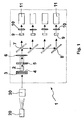
- an optical device for the metering of electromagnetic radiations emitted by an electromagnetic radiation source 20.
- a material 30 under examination material which may be of gaseous or solid type and is positioned in front of a sensor.
- the electromagnetic radiation beam emitted by the source 20 is partially intercepted by the gas or solids under examination and then enters the device 1.
- the electromagnetic radiation meets a first diaphragm 3, reducing the intensity thereof, and subsequently a first lenses 4 that, by means of a tubular duct 2, focuses the radiation on a second diaphragm 5.
- the diameter of this second diaphragm 5 defines the dimensions of the emitting surface and assures that all of the electromagnetic radiation entering the device 1 be subjected to metering.
- a second lens 6 is present, with the task of focusing the electromagnetic radiation in a spot proximal to the location of the subsequent component.
- the beam Downstream of the second lens 6 the beam is sent into a portion of the metering device 1 comprising means for selecting the electromagnetic radiation emitted from the source 20. Purpose of said means is to produce at least two fractions of electromagnetic radiations to be directed to as many optical filters.
- optical filters may be selected among the following typologies: interference filters, neutral-density filters, absorption filters, reflection filters, IR filters.
- the device of the invention may be made according to two variants.
- a first variant not shown in the figure, uses interference filters mounted on a wheel that, by rotating, alternatively interposes first the one filter and then the other one to the radiation beam.
- the advantage of this configuration lies in having a single detector and a single set of optical components, something that can facilitate the device setup and improve the metering accuracy.
- the selecting means comprises instead one or more elements 7 for distributing the beam, forming two beam fractions that can then be filtered and detected separately.
- the main advantage lies in detecting the radiation at the two different wavelengths in the same instant. This fact can be fundamental when it is desirable to analyze phenomena changing quite rapidly over time, like for example phenomena rapidly modifying the intensity of the electromagnetic radiation.
- the beam distributing elements 7 are made of elements of the type distributing electromagnetic radiation.
- the radiation is split up by said elements 7 into at least two alike beams: one beam sent directly to an optical filter 9 and the other one sent to a second distributing element 7 which in turn splits it up into other two fractions.
- Such mirrors have the task of deflecting the radiation, so as to reduce the dimensions of the apparatus.
- the photodetectors 11 have the task of detecting the electromagnetic radiation peculiar of the process being analyzed, like for example UV radiation, IR radiation, CO-absorption radiation, CO 2 -absorption radiation, CH 4 -absorption radiation, etc.
- Preferred photodetectors are of the lead selenide (PbSe) type with electronic control of the temperature, of the thermopile type, and of the multiplier phototube type.
- Purpose of the thermoregulation is to stabilize the temperature of the sensing surface of the detector. Thus, all external disturbance factors are minimized, mainly the temperature changes localized near the detector, and the signal/noise ratio is improved; here for “signal” it is meant the voltage signal produced by the photodetector, which is subsequently amplified by an optional preamplifier (not shown in the figure) and then acquired by a computer.
- the device of the invention is particularly suitable for the on-line controlling of production processes, like electric furnace melting processes, where the light source 20 is in the inner zone of the electric furnace and is made by the electric arc, the incandescent material being melt, the slag or the refractory.
- the optical device for metering may be positioned, for example, onto the end section of a lance, or housed in a suitable cooled unit.
- the metering device described hereto was used for the controlling of the production process of steel in an electric furnace, not merely at the final phase of the process but also at the initial one, since in the initial phase the presence of scrap between the inside of the furnace and the sensor shields the UV-IR radiations commonly in use for these purposes, not allowing an effective controlling of the process by means of the current systems.
- the device of the invention through its being capable of monitoring the presence of some chemical species present in front of the sensor, provides a quantitative indication with regard to the progress of the melting front.
- the senor is capable of determining in the first instance the progress of the melting front. For the determining of phase i) it is used the IR signal compared to a threshold value below which the scrap completely covers the arc. In this phase the metering performed at the wavelengths peculiar to the analyzed chemical species, for example CO, CO 2 , CH 4 , provide a key indication with regard to the progress of the melting front.
- the senor uses the metering of the UV/IR ratio, which should be higher than a threshold value.
- the senor uses the metering of the UV/IR ratio, which should be lower than a threshold value.
- metering method there were selected the metering of the UV-IR radiation and the IR absorption spectroscopy, obtained by means of optical filters.
Applications Claiming Priority (1)
| Application Number | Priority Date | Filing Date | Title |
|---|---|---|---|
| ITRM20040433 ITRM20040433A1 (it) | 2004-09-14 | 2004-09-14 | Dispositivo ottico per la misura in linea di radiazioni elettromagnetiche. |
Publications (2)
| Publication Number | Publication Date |
|---|---|
| EP1635155A2 true EP1635155A2 (fr) | 2006-03-15 |
| EP1635155A3 EP1635155A3 (fr) | 2007-11-28 |
Family
ID=35431187
Family Applications (1)
| Application Number | Title | Priority Date | Filing Date |
|---|---|---|---|
| EP05108428A Withdrawn EP1635155A3 (fr) | 2004-09-14 | 2005-09-14 | Dispositif optique pour la mesure en ligne de rayonnement électromagnétique |
Country Status (2)
| Country | Link |
|---|---|
| EP (1) | EP1635155A3 (fr) |
| IT (1) | ITRM20040433A1 (fr) |
Cited By (1)
| Publication number | Priority date | Publication date | Assignee | Title |
|---|---|---|---|---|
| FR2943786A1 (fr) * | 2009-03-31 | 2010-10-01 | Francois Melet | Dispositif d'analyse d'un echantillon sanguin. |
Citations (6)
| Publication number | Priority date | Publication date | Assignee | Title |
|---|---|---|---|---|
| GB1051065A (fr) * | 1963-11-07 | |||
| DE3743584A1 (de) * | 1987-12-22 | 1989-07-13 | Ritzl Hermann | Optisches spektrometer |
| US5041723A (en) * | 1989-09-30 | 1991-08-20 | Horiba, Ltd. | Infrared ray detector with multiple optical filters |
| US5462176A (en) * | 1994-06-03 | 1995-10-31 | Brown & Williamson Tobacco Corporation | Latex detection system |
| US5737076A (en) * | 1992-12-01 | 1998-04-07 | Glaus; Ulrich Walter | Method and apparatus for determining substances and/or the properties thereof |
| US6071114A (en) * | 1996-06-19 | 2000-06-06 | Meggitt Avionics, Inc. | Method and apparatus for characterizing a combustion flame |
-
2004
- 2004-09-14 IT ITRM20040433 patent/ITRM20040433A1/it unknown
-
2005
- 2005-09-14 EP EP05108428A patent/EP1635155A3/fr not_active Withdrawn
Patent Citations (6)
| Publication number | Priority date | Publication date | Assignee | Title |
|---|---|---|---|---|
| GB1051065A (fr) * | 1963-11-07 | |||
| DE3743584A1 (de) * | 1987-12-22 | 1989-07-13 | Ritzl Hermann | Optisches spektrometer |
| US5041723A (en) * | 1989-09-30 | 1991-08-20 | Horiba, Ltd. | Infrared ray detector with multiple optical filters |
| US5737076A (en) * | 1992-12-01 | 1998-04-07 | Glaus; Ulrich Walter | Method and apparatus for determining substances and/or the properties thereof |
| US5462176A (en) * | 1994-06-03 | 1995-10-31 | Brown & Williamson Tobacco Corporation | Latex detection system |
| US6071114A (en) * | 1996-06-19 | 2000-06-06 | Meggitt Avionics, Inc. | Method and apparatus for characterizing a combustion flame |
Cited By (2)
| Publication number | Priority date | Publication date | Assignee | Title |
|---|---|---|---|---|
| FR2943786A1 (fr) * | 2009-03-31 | 2010-10-01 | Francois Melet | Dispositif d'analyse d'un echantillon sanguin. |
| EP2237020A1 (fr) * | 2009-03-31 | 2010-10-06 | François Melet | Dispositif d'analyse d'un échantillon sanguin |
Also Published As
| Publication number | Publication date |
|---|---|
| EP1635155A3 (fr) | 2007-11-28 |
| ITRM20040433A1 (it) | 2004-12-14 |
Similar Documents
| Publication | Publication Date | Title |
|---|---|---|
| RU2312745C2 (ru) | Устройство и способ текущего контроля зоны сварки, а также система и способ управления сваркой | |
| EP0176625B1 (fr) | Méthode et appareil pour l'analyse de l'acier utilisant la spectroscopie d'émission excitée par laser | |
| US6354733B2 (en) | System and method for determining combustion temperature using infrared emissions | |
| KR20130101441A (ko) | 레이저 절단 헤드, 및 레이저 절단 헤드를 이용한 피가공물 절단 방법 | |
| US11079333B2 (en) | Analyzer sample detection method and system | |
| US20060213875A1 (en) | Flame photometric detector of gas chromatograph | |
| JPH1052779A (ja) | 材料処理操作におけるレーザーの収束制御 | |
| EP1635155A2 (fr) | Dispositif optique pour la mesure en ligne de rayonnement électromagnétique | |
| US5170060A (en) | Measuring the flow rate of a thin stream of molten material | |
| US4818106A (en) | Spectral analysis device on a converter | |
| US3903014A (en) | Method of and apparatus for measuring and controlling the rate of carburization of a melt | |
| JP4430261B2 (ja) | 精錬炉内遠隔モニタリング方法および装置 | |
| JP5000379B2 (ja) | レーザ誘起蛍光分析法及びレーザ誘起蛍光分析プローブ | |
| JP3820259B2 (ja) | 溶融スラグの温度計測方法 | |
| JP2001249049A (ja) | 溶融スラグの温度計測方法 | |
| JP2000338039A (ja) | 溶融金属分析方法およびその装置 | |
| KR100603426B1 (ko) | 용융금속의 분석방법 및 그 장치 | |
| JP4255420B2 (ja) | 炎検知器 | |
| JP3563607B2 (ja) | 原子吸光光度計 | |
| JPH0875651A (ja) | レーザ発光分光分析方法 | |
| WO2017181223A1 (fr) | Spectromètre à émission atomique | |
| JP2007044719A (ja) | レーザ加工装置 | |
| JP2895816B2 (ja) | Icp発光分光分析装置 | |
| JP3870959B2 (ja) | 溶融金属分析方法 | |
| CA3230582A1 (fr) | Four de fusion metallurgique et procede de determination de quantite de gaz heteromoleculaire |
Legal Events
| Date | Code | Title | Description |
|---|---|---|---|
| PUAI | Public reference made under article 153(3) epc to a published international application that has entered the european phase |
Free format text: ORIGINAL CODE: 0009012 |
|
| AK | Designated contracting states |
Kind code of ref document: A2 Designated state(s): AT BE BG CH CY CZ DE DK EE ES FI FR GB GR HU IE IS IT LI LT LU LV MC NL PL PT RO SE SI SK TR |
|
| AX | Request for extension of the european patent |
Extension state: AL BA HR MK YU |
|
| PUAL | Search report despatched |
Free format text: ORIGINAL CODE: 0009013 |
|
| AK | Designated contracting states |
Kind code of ref document: A3 Designated state(s): AT BE BG CH CY CZ DE DK EE ES FI FR GB GR HU IE IS IT LI LT LU LV MC NL PL PT RO SE SI SK TR |
|
| AX | Request for extension of the european patent |
Extension state: AL BA HR MK YU |
|
| RIC1 | Information provided on ipc code assigned before grant |
Ipc: G01N 21/35 20060101ALI20071022BHEP Ipc: G01J 3/36 20060101ALI20071022BHEP Ipc: G01J 3/28 20060101AFI20051208BHEP |
|
| 17P | Request for examination filed |
Effective date: 20080522 |
|
| 17Q | First examination report despatched |
Effective date: 20080619 |
|
| AKX | Designation fees paid |
Designated state(s): AT BE BG CH CY CZ DE DK EE ES FI FR GB GR HU IE IS IT LI LT LU LV MC NL PL PT RO SE SI SK TR |
|
| STAA | Information on the status of an ep patent application or granted ep patent |
Free format text: STATUS: THE APPLICATION IS DEEMED TO BE WITHDRAWN |
|
| 18D | Application deemed to be withdrawn |
Effective date: 20081030 |