EP1634489A1 - Sämaschine - Google Patents
Sämaschine Download PDFInfo
- Publication number
- EP1634489A1 EP1634489A1 EP05019182A EP05019182A EP1634489A1 EP 1634489 A1 EP1634489 A1 EP 1634489A1 EP 05019182 A EP05019182 A EP 05019182A EP 05019182 A EP05019182 A EP 05019182A EP 1634489 A1 EP1634489 A1 EP 1634489A1
- Authority
- EP
- European Patent Office
- Prior art keywords
- coulters
- scharbalkens
- frame
- scharbalken
- side frame
- Prior art date
- Legal status (The legal status is an assumption and is not a legal conclusion. Google has not performed a legal analysis and makes no representation as to the accuracy of the status listed.)
- Granted
Links
Images



Classifications
-
- A—HUMAN NECESSITIES
- A01—AGRICULTURE; FORESTRY; ANIMAL HUSBANDRY; HUNTING; TRAPPING; FISHING
- A01C—PLANTING; SOWING; FERTILISING
- A01C7/00—Sowing
- A01C7/20—Parts of seeders for conducting and depositing seed
- A01C7/201—Mounting of the seeding tools
- A01C7/205—Mounting of the seeding tools comprising pressure regulation means
-
- A—HUMAN NECESSITIES
- A01—AGRICULTURE; FORESTRY; ANIMAL HUSBANDRY; HUNTING; TRAPPING; FISHING
- A01B—SOIL WORKING IN AGRICULTURE OR FORESTRY; PARTS, DETAILS, OR ACCESSORIES OF AGRICULTURAL MACHINES OR IMPLEMENTS, IN GENERAL
- A01B63/00—Lifting or adjusting devices or arrangements for agricultural machines or implements
- A01B63/02—Lifting or adjusting devices or arrangements for agricultural machines or implements for implements mounted on tractors
- A01B63/10—Lifting or adjusting devices or arrangements for agricultural machines or implements for implements mounted on tractors operated by hydraulic or pneumatic means
-
- A—HUMAN NECESSITIES
- A01—AGRICULTURE; FORESTRY; ANIMAL HUSBANDRY; HUNTING; TRAPPING; FISHING
- A01B—SOIL WORKING IN AGRICULTURE OR FORESTRY; PARTS, DETAILS, OR ACCESSORIES OF AGRICULTURAL MACHINES OR IMPLEMENTS, IN GENERAL
- A01B63/00—Lifting or adjusting devices or arrangements for agricultural machines or implements
- A01B63/14—Lifting or adjusting devices or arrangements for agricultural machines or implements for implements drawn by animals or tractors
- A01B63/24—Tools or tool-holders adjustable relatively to the frame
- A01B63/32—Tools or tool-holders adjustable relatively to the frame operated by hydraulic or pneumatic means without automatic control
Definitions
- the invention relates to a sowing machine with a frame, on which a transverse to the direction of travel and horizontally extending Scharbalken is arranged, on which the Scharhalter the coulters are articulated.
- Such seeders are known.
- resilient elements are arranged between the coulter holder and the frame.
- coupling elements are arranged in the prior art on the front of the frame, by means of which the entire seed drill is pivotable about an axis extending transversely to the direction of travel, so that the coulters next to the Lifting by the three-point hitch be lifted off the ground by pivoting the machine.
- the entire rotation of the drill is disadvantageous and expensive.
- the invention has the object to provide a simpler pivoting of the coulters to increase the distance to the ground for the purpose of lifting off the ground.
- the size of the Federkraftbeetzschlagung thereby adjust that the actuator an adjustable stop for setting the max. Stroke path of the actuating element is assigned.
- the desired spring force can be the desired spring force by means of which the coulters are applied in the direction of the soil preset.
- the taper bar consists of two parts, each part of the Scharbalkens rotatably arranged on a side frame and each part of the Scharbalkens is associated with a motor control element, and that each part of the Scharbalkens is mounted on a side frame which is articulated by means of a pointing in the direction of travel hinge axis exhibiting joint on the frame, and that between the side frame and the frame in each case a motor control element is arranged.
- the drill has the frame 1. On the front of the frame 1 three-point coupling elements 2 are arranged for mounting the frame 1 to the three-point power lift of a tractor. To the frame 1 are by means of the joints 3, each having a pointing in the direction of travel 4 pivot axis. 5 have arranged, the side frame 6. Between the frame 1 and the respective side frame 6, the double-acting hydraulic cylinders 7 are arranged, by means of which the side frame 6 from the position shown in Fig. 1, in which the side frames 6 extend transversely to the direction 4 in a horizontal position, in the in Figs 2 and 3 to pivot for the purpose of transport.
- a share bar 8 is rotatably supported by means of the bearing 9 in each case.
- a Scharbalken 8 is arranged so that the Scharbalken 8 consists of two parts. Each part of the Scharbalkens 8 is rotatably mounted on the associated side frame 6.
- a lever 10 is arranged at the respective outer end of the Scharbalkens 8.
- motor actuating element is arranged, by means of which the Scharbalken 8 is rotatable.
- the strut 12 is arranged at its one end 14 on the bolt 15, with which the hydraulic cylinder 11 is connected to the arranged on the Scharbalken 8 lever 10.
- the slot 13 of the strut 12 of the arranged on the other side 16 of the adjusting element 11 pin 17, with which the other side 16 of the adjusting element 11 is connected to the side frame 6 engages.
- On the side 16, on which the slot 13 is arranged in the strut 12, designed as a screw 18 stop is arranged, which comes to rest on the hydraulic cylinder 11.
- this designed as an adjustable stop screw 18 the maximum stroke of the control element 11 is adjustable.
- the lower Scharhalter 20 of the coulters 21 are resiliently mounted by means of a rubber spring bearing 19.
- the coulters 21 are further articulated by means of an upper handlebar 22 to the frame 6.
- a plurality of coulters 21 are arranged spaced from each other, wherein in Fig. 1 for each side frame 6 only one coulter 21 is located.
- the coulters 21 By pivoting the Scharbalkens 8 via the motor control element 11, the coulters 21 can be acted upon with spring pressure down on the rubber mounting 19. The corresponding resilient load of the coulters 21 in the direction of the bottom can be adjusted with the above-described stop 18.
- the coulter holder 20 and the coulters 21 in the direction of the bottom can be acted upon by spring force.
- the Scharbalkens 8 in the direction of arrow 22 the coulters 21 from the ground or take off and at the same time thereby retract, so that they in transport position from the outer position shown in Fig. 2 in the position shown in FIG. 3 inwardly be retracted so as to obtain the narrowest possible transport width.
- the advantage of the adjustable stop 18 of the strut 12 is given in particular with two or more split Scharbalken 8, with multiple actuators 11, because of the stop 18 for all Scharbalken and thus all coulters 21 of the same adjustment and thus the corresponding coulter pressure is adjustable.
- the coulters 21 according to FIGS. 9-11 differ from the arrangement of the coulters 21 according to FIGS. 1-8 in that the hydraulic cylinder 11 is assigned no strut 12.
- the max. Twisting of the Scharbalkens 8 via the double-acting hydraulic cylinder 11 is effected by the appropriate length selection of the hydraulic cylinder eleventh
Landscapes
- Life Sciences & Earth Sciences (AREA)
- Soil Sciences (AREA)
- Environmental Sciences (AREA)
- Engineering & Computer Science (AREA)
- Mechanical Engineering (AREA)
- Zoology (AREA)
- Soil Working Implements (AREA)
- Agricultural Machines (AREA)
Abstract
Description
- Die Erfindung betrifft eine Sämaschine mit einem Rahmen, an dem ein quer zur Fahrtrichtung und horizontal verlaufender Scharbalken angeordnet ist, an welchem Scharhalter der Säschare angelenkt sind.
- Derartige Sämaschinen sind bekannt. Um die Säschare in Richtung des Bodens federnd zu belasten, sind zwischen dem Scharhalter und dem Rahmen federnde Elemente angeordnet. Um für die Säschare beim Ausheben aus dem Boden einen ausreichend großen Abstand zu erhalten, sind beim Stand der Technik auf der Vorderseite des Rahmens Kupplungselemente angeordnet, mittels welchem die gesamte Sämaschine um eine quer zur Fahrtrichtung verlaufende Achse verschwenkbar ist, so dass die Säschare neben dem Ausheben durch den Dreipunktkraftheber durch Verschwenken der Maschine vom Boden abgehoben werden. Das gesamte Verdrehen der Sämaschine ist nachteilig und aufwendig.
- Der Erfindung liegt die Aufgabe zugrunde, eine einfachere Verschwenkung der Säschare zur Vergrößerung des Abstandes zum Boden zum Zwecke des Abhebens vom Boden vorzuschlagen.
- Diese Aufgabe wird erfindungsgemäß durch die Merkmale des Anspruches 1 gelöst. Infolge dieser Maßnahmen wird es durch die verdrehbare Lagerung des Scharbalkens in einfacher Weise möglich, die Säschare durch Verdrehen des Scharbalkens aus dem Boden aus oder vom Boden abzuheben. Gleichzeitig können durch die integrierte federnde Gummilagerung der Schare an dem Scharbalken durch entsprechendes entgegengesetztes Verdrehen des Scharbalkens die Säschare in Richtung des Bodens mit der gewünschten Federkraft beaufschlagt werden.
- In einfacher Weise lässt sich die Größe der Federkraftbeaufschlagung dadurch einstellen, dass dem Stellelement ein einstellbarer Anschlag zur Einstellung des max. Hubweges des Stellelementes zugeordnet ist. Infolge dieser Maßnahmen lässt sich die gewünschte Federkraft mittels welcher die Säschare in Richtung des Bodens beaufschlagt werden, voreinstellen.
- Eine vorteilhafte Führung der Säschare gegenüber dem Scharbalken und der Bodenoberfläche wird dadurch erreicht, dass die Säschare mittels eines unteren Scharhalters und einer oberen Lenkerstrebe, die eine parallelogrammähnliche Anordnung bilden, angelenkt sind.
- Bei einer Sämaschine mit großer Arbeitsbreite bei der zur Erreichung einer schmalen Transportbreite die Seitenrahmen einklappbar sind, ist vorgesehen, dass der Scharbalken aus zwei Teilen besteht, wobei jeder Teil des Scharbalkens an einem Seitenrahmen verdrehbar angeordnet und jedem Teil des Scharbalkens ein motorisches Stellelement zugeordnet ist, und dass jeder Teil des Scharbalkens an einem Seitenrahmen gelagert ist, der mittels eines eine in Fahrtrichtung weisenden Gelenkachse aufweisendes Gelenk am Rahmen angelenkt ist, und dass zwischen dem Seitenrahmen und dem Rahmen jeweils ein motorisches Stellelement angeordnet ist.
- Weitere Einzelheiten der Erfindung sind der Beispielsbeschreibung und den Zeichnungen zu entnehmen. Hierbei zeigen
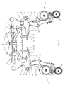
- Fig. 1
- die Sämaschine mit ausgeklappten Seitenrahmen in der Draufsicht,
- Fig. 2
- die Sämaschine in Transportstellung mit eingeklappten Seitenrahmen in der Draufsicht und in vergrößertem Maßstab,
- Fig. 3
- die Sämaschine in Transportstellung mit eingezogenen Säscharen in der Draufsicht,
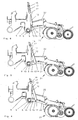
- Fig. 4
- die an dem Seitenrahmen angeordneten Säschare in unterster Position und in Seitenansicht,
- Fig. 5
- die Säschare in Arbeitsstellung und in Seitenansicht,
- Fig. 6
- die Säschare in angehobener bzw. eingezogener Position in Seitenansicht,
- Fig. 7
- das Stellelement zum Verdrehen des Scharbalkens in der Ansicht VII - VII,
- Fig. 8
- das Stellelement in Seitenansicht,
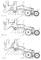
- Fig. 9
- am Seitenrahmen angeordnete Säschare in unterster Stellung in Seitenansicht,
- Fig. 10
- am Seitenrahmen angeordnete Säschare gemäß Fig. 9 in Arbeitsstellung in Seitenansicht und
- Fig. 11
- die Säschare gemäß Fig. 9 in ausgehobener bzw. eingezogener Position in Seitenansicht.
- Die Sämaschine weist den Rahmen 1 auf. Auf der Vorderseite des Rahmens 1 sind Dreipunktkupplungselemente 2 zum Anbau des Rahmens 1 an den Dreipunkkraftheber eines Ackerschleppers angeordnet. An den Rahmen 1 sind mittels der Gelenke 3, die jeweils eine in Fahrtrichtung 4 weisende Schwenkachse 5 aufweisen, die Seitenrahmen 6 angeordnet. Zwischen dem Rahmen 1 und dem jeweiligen Seitenrahmen 6 sind die doppeltwirkenden Hydraulikzylinder 7 angeordnet, mittels welchem die Seitenrahmen 6 aus der in Fig. 1 dargestellten Position, in welcher sich die Seitenrahmen 6 quer zur Fahrtrichtung 4 in horizontaler Lage erstrecken, in die in den Fig. 2 und 3 dargestellte aufrechte Position zum Zwecke des Transportes zu verschwenken.
- An den Seitenrahmen 6 ist jeweils ein Scharbalken 8 mittels der Lager 9 verdrehbar gelagert. An jedem Seitenrahmen 6 ist ein Scharbalken 8 angeordnet, so dass der Scharbalken 8 aus zwei Teilen besteht. Jeder Teil des Scharbalkens 8 ist an dem zugeordneten Seitenrahmen 6 verdrehbar gelagert. An dem jeweils äußeren Ende des Scharbalkens 8 ist ein Hebel 10 angeordnet. Zwischen dem äußeren Ende 11 des Hebels 10 und dem Seitenrahmen 6 ist das als doppeltwirkender Hydraulikzylinder 11 ausgebildete motorische Stellelement angeordnet, mittels welchem der Scharbalken 8 verdrehbar ist. Dem Hydraulikzylinder 11 ist die Strebe 12, in welcher ein Langloch 13 angeordnet ist, zugeordnet. Die Strebe 12 ist an ihrem einen Ende 14 auf dem Bolzen 15 angeordnet, mit dem der Hydraulikzylinder 11 mit dem an dem Scharbalken 8 angeordneten Hebel 10 verbunden ist. In das Langloch 13 der Strebe 12 greift der auf der anderen Seite 16 des Stellelementes 11 angeordnete Bolzen 17, mit dem die andere Seite 16 des Stellelementes 11 mit dem Seitenrahmen 6 verbunden ist. Auf der Seite 16, auf welcher das Langloch 13 in der Strebe 12 angeordnet ist, ist eine als Schraubspindel 18 ausgebildeter Anschlag angeordnet, der an dem Hydraulikzylinder 11 zur Anlage kommt. Mittels dieser als einstellbarer Anschlag ausgebildete Schraubspindel 18 ist der maximale Hubweg des Stellelementes 11 einstellbar. Hierüber kann der Verschwenkweg 8 des Scharbalkens 8 und max. mögliche Schardruck begrenzt werden.
- Auf dem Scharbalken 8, der als Quadratrohr ausgebildet ist, sind mittels einer Gummifederlagerung 19 die unteren Scharhalter 20 der Säschare 21 federnd gelagert. Um eine parallelogrammähnliche Anordnung der Säschare 21 zu erhalten, sind die Säschare 21 weiterhin mittels einer oberen Lenkerstrebe 22 an dem Rahmen 6 angelenkt. An dem Scharbalken 8 sind mehrere Säschare 21 beabstandet zueinander angeordnet, wobei in Fig. 1 für jeden Seitenrahmen 6 nur ein Säschar 21 eingezeichnet ist.
- Durch Verschwenken des Scharbalkens 8 über das motorische Stellelement 11 können die Säschare 21 mit Federdruck nach unten über die Gummilagerung 19 beaufschlagt werden. Die entsprechende federnde Belastung der Säschare 21 in Richtung des Bodens lässt sich mit dem vorbeschriebenen Anschlag 18 einstellen. Somit sind mittels der Hydraulikzylinder 11 die Scharhalter 20 und die Säschare 21 in Richtung des Bodens mit Federkraft beaufschlagbar. Andererseits lassen sich durch das Verdrehen des Scharbalkens 8 in Pfeilrichtung 22 die Säschare 21 vom Boden aus- oder abheben und gleichzeitig hierdurch einziehen, so dass sie in Transportstellung aus der in Fig. 2 dargestellten äußeren Position in die in Fig. 3 dargestellte Position nach innen eingezogen werden, um so eine möglichst schmale Transportbreite zu erhalten.
- Der Vorteil des einstellbaren Anschlages 18 der Strebe 12 ist insbesondere bei zwei oder mehr geteilten Scharbalken 8, mit mehreren Stellelementen 11 gegeben, weil über den Anschlag 18 für alle Scharbalken und somit alle Säschare 21 der gleiche Verstellweg und somit der entsprechende Schardruck einstellbar ist.
- Die Säschare 21 gemäß den Fig. 9-11 unterscheiden sich von der Anordnung der Säschare 21 gemäß den Fig. 1-8 dadurch, dass dem Hydraulikzylinder 11 keine Strebe 12 zugeordnet ist. Die max. Verdrehung des Scharbalkens 8 über den doppeltwirkenden Hydraulikzylinder 11 erfolgt durch die entsprechende Längenauswahl des Hydraulikzylinders 11.
Claims (4)
- Sämaschine mit einem Rahmen (1, 6), an dem ein quer zur Fahrtrichtung (4) und horizontal verlaufender Scharbalken (8) um seine Längsachse mittels eines, vorzugsweise motorischen Stellelementes (11) verdrehbar angeordnet ist, wobei die Scharhalter (20) der Säschare (21) mittels einer federnden Gummilagerung (19) an dem Scharbalken (8) angelenkt sind, wobei durch Verdrehen des Scharbalkens (8) mittels des Stellelementes (11) in die eine Richtung die Scharhalter (20) und Säschare (21) in Richtung des Bodens mit Federkraft beaufschlagbar und durch Verdrehen in die entgegengesetzte Drehrichtung die Säschare (21) aus dem und/oder vom Boden aus- und/oder anhebbar sind.
- Sämaschine nach Anspruch 1, dadurch gekennzeichnet, dass dem Stellelement (11) ein einstellbarer Anschlag (18) zur Einstellung des max. Hubweges des Stellelementes (11) zugeordnet ist.
- Sämaschine nach Anspruch 1, dadurch gekennzeichnet, dass die Säschare (21) mittels eines unteren Scharhalters (20) und einer oberen Lenkerstrebe (22), die eine parallelogrammähnliche Anordnung bilden, angelenkt sind.
- Sämaschine nach einem oder mehreren der vorstehenden Ansprüche, dadurch gekennzeichnet, dass der Scharbalken (8) aus zwei Teilen besteht, wobei jeder Teil des Scharbalkens (8) an einem Seitenrahmen (6) verdrehbar angeordnet und jedem Teil des Scharbalkens (8) ein motorisches Stellelement (11) zugeordnet ist, und dass jeder Teil des Scharbalkens (8) an einem Seitenrahmen (6) gelagert ist, der mittels eines eine in Fahrtrichtung (4) weisenden Gelenkachse aufweisendes Gelenk (3) am Rahmen (1) angelenkt ist, und dass zwischen dem Seitenrahmen und dem Rahmen jeweils ein motorisches Stellelement angeordnet ist.
Priority Applications (1)
| Application Number | Priority Date | Filing Date | Title |
|---|---|---|---|
| PL05019182T PL1634489T3 (pl) | 2004-09-09 | 2005-09-03 | Siewnik |
Applications Claiming Priority (1)
| Application Number | Priority Date | Filing Date | Title |
|---|---|---|---|
| DE102004043565A DE102004043565A1 (de) | 2004-09-09 | 2004-09-09 | Sämaschine |
Publications (2)
| Publication Number | Publication Date |
|---|---|
| EP1634489A1 true EP1634489A1 (de) | 2006-03-15 |
| EP1634489B1 EP1634489B1 (de) | 2012-10-24 |
Family
ID=35447736
Family Applications (1)
| Application Number | Title | Priority Date | Filing Date |
|---|---|---|---|
| EP05019182A Expired - Lifetime EP1634489B1 (de) | 2004-09-09 | 2005-09-03 | Sämaschine |
Country Status (3)
| Country | Link |
|---|---|
| EP (1) | EP1634489B1 (de) |
| DE (1) | DE102004043565A1 (de) |
| PL (1) | PL1634489T3 (de) |
Cited By (6)
| Publication number | Priority date | Publication date | Assignee | Title |
|---|---|---|---|---|
| FR2904181A1 (fr) * | 2006-07-27 | 2008-02-01 | Poettinger Alois Maschf | Machine agricole, notamment semoir semi-porte |
| EP1964459A1 (de) * | 2007-03-02 | 2008-09-03 | Rauch Landmaschinenfabrik Gmbh | Sämaschine |
| EP2055166A1 (de) | 2007-11-05 | 2009-05-06 | Kverneland ASA | Saatgut- und/oder Düngerverteilmaschine |
| EP2055167A1 (de) * | 2007-10-30 | 2009-05-06 | Amazonen-Werke H. Dreyer GmbH & Co. KG | Sämaschine |
| FR2956560A1 (fr) * | 2010-02-25 | 2011-08-26 | Kuhn Sa | Semoir avec dispositifs de reglage a encombrement reduit |
| EP2982230A1 (de) | 2014-08-05 | 2016-02-10 | Amazonen-Werke H. Dreyer GmbH & Co. KG | Sämaschine |
Families Citing this family (8)
| Publication number | Priority date | Publication date | Assignee | Title |
|---|---|---|---|---|
| DE102007028193A1 (de) | 2007-06-20 | 2008-12-24 | Amazonen-Werke H. Dreyer Gmbh & Co. Kg | Sämaschine |
| DE102014002911A1 (de) * | 2014-02-28 | 2015-09-03 | Alois Pöttinger Maschinenfabrik Gmbh | Landwirtschaftliche Bodenbearbeitungsmaschine |
| DE102014109565A1 (de) | 2014-07-09 | 2016-01-14 | Amazonen-Werke H. Dreyer Gmbh & Co. Kg | Sämaschine |
| US11700781B2 (en) | 2019-05-15 | 2023-07-18 | Great Plains Manufacturing, Inc. | Ground opener with skewed support assembly |
| WO2020232344A1 (en) | 2019-05-15 | 2020-11-19 | Great Plains Manufacturing, Inc. | Ground openers with common depth-adjustment |
| WO2020232341A1 (en) | 2019-05-15 | 2020-11-19 | Great Plains Manufacturing, Inc. | Ground opener with floating opener body |
| DE102019118149A1 (de) * | 2019-07-04 | 2021-01-07 | Amazonen-Werke H. Dreyer Gmbh & Co. Kg | Sämaschine |
| DE102020109975A1 (de) | 2020-04-09 | 2021-10-28 | Amazonen-Werke H. Dreyer SE & Co. KG | Landwirtschaftliche Arbeitsmaschine und Verfahren zum Betreiben einer landwirtschaftlichen Arbeitsmaschine |
Citations (8)
| Publication number | Priority date | Publication date | Assignee | Title |
|---|---|---|---|---|
| GB2177885A (en) * | 1985-07-25 | 1987-02-04 | Massey Ferguson Mfg | Agricultural drills |
| GB2197573A (en) * | 1986-10-30 | 1988-05-25 | Massey Ferguson Mfg | An agricultural implement |
| DE19644751A1 (de) * | 1995-10-31 | 1997-05-07 | Lemken Gmbh & Co Kg | Drillmaschine mit Stellvorrichtung für Säschar und Druckrolle |
| DE29910414U1 (de) * | 1999-06-15 | 1999-08-26 | Horsch Maschinen GmbH, 92421 Schwandorf | Säscharanordnung |
| EP1285564A1 (de) * | 2001-08-23 | 2003-02-26 | Amazonen-Werke H. Dreyer GmbH & Co. KG | Sämaschine mit Tiefeneinstellung durch ein hydraulisches Ausgleichssystem |
| US6701857B1 (en) * | 2003-01-16 | 2004-03-09 | Lynn David Jensen | Depth control device for planting implement |
| EP1417876A1 (de) * | 2002-10-25 | 2004-05-12 | Deere & Company | Einstellsystem |
| EP1529432A1 (de) * | 2003-11-06 | 2005-05-11 | Kuhn-Nodet S.A. | Sseeder with an adjusting device |
-
2004
- 2004-09-09 DE DE102004043565A patent/DE102004043565A1/de not_active Withdrawn
-
2005
- 2005-09-03 PL PL05019182T patent/PL1634489T3/pl unknown
- 2005-09-03 EP EP05019182A patent/EP1634489B1/de not_active Expired - Lifetime
Patent Citations (8)
| Publication number | Priority date | Publication date | Assignee | Title |
|---|---|---|---|---|
| GB2177885A (en) * | 1985-07-25 | 1987-02-04 | Massey Ferguson Mfg | Agricultural drills |
| GB2197573A (en) * | 1986-10-30 | 1988-05-25 | Massey Ferguson Mfg | An agricultural implement |
| DE19644751A1 (de) * | 1995-10-31 | 1997-05-07 | Lemken Gmbh & Co Kg | Drillmaschine mit Stellvorrichtung für Säschar und Druckrolle |
| DE29910414U1 (de) * | 1999-06-15 | 1999-08-26 | Horsch Maschinen GmbH, 92421 Schwandorf | Säscharanordnung |
| EP1285564A1 (de) * | 2001-08-23 | 2003-02-26 | Amazonen-Werke H. Dreyer GmbH & Co. KG | Sämaschine mit Tiefeneinstellung durch ein hydraulisches Ausgleichssystem |
| EP1417876A1 (de) * | 2002-10-25 | 2004-05-12 | Deere & Company | Einstellsystem |
| US6701857B1 (en) * | 2003-01-16 | 2004-03-09 | Lynn David Jensen | Depth control device for planting implement |
| EP1529432A1 (de) * | 2003-11-06 | 2005-05-11 | Kuhn-Nodet S.A. | Sseeder with an adjusting device |
Cited By (9)
| Publication number | Priority date | Publication date | Assignee | Title |
|---|---|---|---|---|
| FR2904181A1 (fr) * | 2006-07-27 | 2008-02-01 | Poettinger Alois Maschf | Machine agricole, notamment semoir semi-porte |
| AT504058B1 (de) * | 2006-07-27 | 2008-11-15 | Poettinger Ohg Alois | Landmaschine |
| EP1964459A1 (de) * | 2007-03-02 | 2008-09-03 | Rauch Landmaschinenfabrik Gmbh | Sämaschine |
| EP2055167A1 (de) * | 2007-10-30 | 2009-05-06 | Amazonen-Werke H. Dreyer GmbH & Co. KG | Sämaschine |
| EP2055166A1 (de) | 2007-11-05 | 2009-05-06 | Kverneland ASA | Saatgut- und/oder Düngerverteilmaschine |
| FR2956560A1 (fr) * | 2010-02-25 | 2011-08-26 | Kuhn Sa | Semoir avec dispositifs de reglage a encombrement reduit |
| EP2361491A1 (de) * | 2010-02-25 | 2011-08-31 | Kuhn S.A. | Sämaschine mit Einstellvorrichtungen mit verringertem Raumbedarf |
| EP2982230A1 (de) | 2014-08-05 | 2016-02-10 | Amazonen-Werke H. Dreyer GmbH & Co. KG | Sämaschine |
| DE102014111099A1 (de) | 2014-08-05 | 2016-02-11 | Amazonen-Werke H. Dreyer Gmbh & Co. Kg | Sämaschine |
Also Published As
| Publication number | Publication date |
|---|---|
| PL1634489T3 (pl) | 2013-03-29 |
| EP1634489B1 (de) | 2012-10-24 |
| DE102004043565A1 (de) | 2006-03-30 |
Similar Documents
| Publication | Publication Date | Title |
|---|---|---|
| EP1634489B1 (de) | Sämaschine | |
| EP2005811A2 (de) | Sämaschine | |
| EP3427559A1 (de) | Anbaudrehpflug | |
| DE102006039513B4 (de) | Wendepflug | |
| EP0796553B1 (de) | Sägerät, insbesondere für Mulchsaat | |
| EP1529431B1 (de) | Sämaschine | |
| DE3343847C2 (de) | ||
| EP0036203A1 (de) | Zugwiderstandsregelung für Traktoren | |
| DE102014015881B4 (de) | Bodenbearbeitungsmaschine | |
| EP1060649B1 (de) | Schlepperbetriebene Sämaschine mit Säscharanordnung und Dreipunkt-Anhängung | |
| DE102006034798B4 (de) | Landmaschine | |
| AT13221U1 (de) | Gezogene landwirtschaftliche Maschine | |
| DE19644751A1 (de) | Drillmaschine mit Stellvorrichtung für Säschar und Druckrolle | |
| DE102015100273A1 (de) | Landwirtschaftliches Arbeitsgerät mit Zusatzfahrwerk | |
| EP0858258B1 (de) | Drillmaschine mit stellvorrichtung für säschar und druckrolle | |
| DE4306145A1 (de) | Gerätekombination zum Pflügen landwirtschaftlicher Nutzflächen und zur Bodennachbearbeitung und/oder Bodenbestellung | |
| DE3431796C2 (de) | ||
| DE60007464T2 (de) | Sämaschine | |
| DE102010013470B4 (de) | Vorrichtung zum Verteilen von Saatgut und/oder Dünger | |
| EP4014702A1 (de) | Zustreich- und einebnungseinrichtung | |
| EP0471156B1 (de) | Kombinationsgerät zur Bodenbearbeitung | |
| AT527100B1 (de) | Landwirtschaftliche Maschine | |
| DE102019107678B3 (de) | Landwirtschaftliche Mähvorrichtung | |
| EP1700518A1 (de) | Sämaschine mit einem Rahmen | |
| EP4074157A1 (de) | Landwirtschaftliche maschine mit zumindest einem ausleger |
Legal Events
| Date | Code | Title | Description |
|---|---|---|---|
| PUAI | Public reference made under article 153(3) epc to a published international application that has entered the european phase |
Free format text: ORIGINAL CODE: 0009012 |
|
| AK | Designated contracting states |
Kind code of ref document: A1 Designated state(s): AT BE BG CH CY CZ DE DK EE ES FI FR GB GR HU IE IS IT LI LT LU LV MC NL PL PT RO SE SI SK TR |
|
| AX | Request for extension of the european patent |
Extension state: AL BA HR MK YU |
|
| 17P | Request for examination filed |
Effective date: 20060725 |
|
| AKX | Designation fees paid |
Designated state(s): AT BE BG CH CY CZ DE DK EE ES FI FR GB GR HU IE IS IT LI LT LU LV MC NL PL PT RO SE SI SK TR |
|
| GRAP | Despatch of communication of intention to grant a patent |
Free format text: ORIGINAL CODE: EPIDOSNIGR1 |
|
| RIN1 | Information on inventor provided before grant (corrected) |
Inventor name: JOHANNABER, STEFAN, JAN |
|
| GRAS | Grant fee paid |
Free format text: ORIGINAL CODE: EPIDOSNIGR3 |
|
| GRAA | (expected) grant |
Free format text: ORIGINAL CODE: 0009210 |
|
| AK | Designated contracting states |
Kind code of ref document: B1 Designated state(s): AT BE BG CH CY CZ DE DK EE ES FI FR GB GR HU IE IS IT LI LT LU LV MC NL PL PT RO SE SI SK TR |
|
| REG | Reference to a national code |
Ref country code: GB Ref legal event code: FG4D Free format text: NOT ENGLISH |
|
| REG | Reference to a national code |
Ref country code: CH Ref legal event code: EP |
|
| REG | Reference to a national code |
Ref country code: AT Ref legal event code: REF Ref document number: 580381 Country of ref document: AT Kind code of ref document: T Effective date: 20121115 |
|
| REG | Reference to a national code |
Ref country code: IE Ref legal event code: FG4D Free format text: LANGUAGE OF EP DOCUMENT: GERMAN |
|
| REG | Reference to a national code |
Ref country code: DE Ref legal event code: R096 Ref document number: 502005013202 Country of ref document: DE Effective date: 20121220 |
|
| REG | Reference to a national code |
Ref country code: SE Ref legal event code: TRGR |
|
| REG | Reference to a national code |
Ref country code: PL Ref legal event code: T3 |
|
| REG | Reference to a national code |
Ref country code: NL Ref legal event code: VDEP Effective date: 20121024 |
|
| PG25 | Lapsed in a contracting state [announced via postgrant information from national office to epo] |
Ref country code: FI Free format text: LAPSE BECAUSE OF FAILURE TO SUBMIT A TRANSLATION OF THE DESCRIPTION OR TO PAY THE FEE WITHIN THE PRESCRIBED TIME-LIMIT Effective date: 20121024 Ref country code: ES Free format text: LAPSE BECAUSE OF FAILURE TO SUBMIT A TRANSLATION OF THE DESCRIPTION OR TO PAY THE FEE WITHIN THE PRESCRIBED TIME-LIMIT Effective date: 20130204 Ref country code: NL Free format text: LAPSE BECAUSE OF FAILURE TO SUBMIT A TRANSLATION OF THE DESCRIPTION OR TO PAY THE FEE WITHIN THE PRESCRIBED TIME-LIMIT Effective date: 20121024 Ref country code: IS Free format text: LAPSE BECAUSE OF FAILURE TO SUBMIT A TRANSLATION OF THE DESCRIPTION OR TO PAY THE FEE WITHIN THE PRESCRIBED TIME-LIMIT Effective date: 20130224 |
|
| PG25 | Lapsed in a contracting state [announced via postgrant information from national office to epo] |
Ref country code: LV Free format text: LAPSE BECAUSE OF FAILURE TO SUBMIT A TRANSLATION OF THE DESCRIPTION OR TO PAY THE FEE WITHIN THE PRESCRIBED TIME-LIMIT Effective date: 20121024 Ref country code: SI Free format text: LAPSE BECAUSE OF FAILURE TO SUBMIT A TRANSLATION OF THE DESCRIPTION OR TO PAY THE FEE WITHIN THE PRESCRIBED TIME-LIMIT Effective date: 20121024 Ref country code: CY Free format text: LAPSE BECAUSE OF FAILURE TO SUBMIT A TRANSLATION OF THE DESCRIPTION OR TO PAY THE FEE WITHIN THE PRESCRIBED TIME-LIMIT Effective date: 20121024 Ref country code: GR Free format text: LAPSE BECAUSE OF FAILURE TO SUBMIT A TRANSLATION OF THE DESCRIPTION OR TO PAY THE FEE WITHIN THE PRESCRIBED TIME-LIMIT Effective date: 20130125 Ref country code: PT Free format text: LAPSE BECAUSE OF FAILURE TO SUBMIT A TRANSLATION OF THE DESCRIPTION OR TO PAY THE FEE WITHIN THE PRESCRIBED TIME-LIMIT Effective date: 20130225 |
|
| PG25 | Lapsed in a contracting state [announced via postgrant information from national office to epo] |
Ref country code: SK Free format text: LAPSE BECAUSE OF FAILURE TO SUBMIT A TRANSLATION OF THE DESCRIPTION OR TO PAY THE FEE WITHIN THE PRESCRIBED TIME-LIMIT Effective date: 20121024 Ref country code: BG Free format text: LAPSE BECAUSE OF FAILURE TO SUBMIT A TRANSLATION OF THE DESCRIPTION OR TO PAY THE FEE WITHIN THE PRESCRIBED TIME-LIMIT Effective date: 20130124 Ref country code: CZ Free format text: LAPSE BECAUSE OF FAILURE TO SUBMIT A TRANSLATION OF THE DESCRIPTION OR TO PAY THE FEE WITHIN THE PRESCRIBED TIME-LIMIT Effective date: 20121024 Ref country code: EE Free format text: LAPSE BECAUSE OF FAILURE TO SUBMIT A TRANSLATION OF THE DESCRIPTION OR TO PAY THE FEE WITHIN THE PRESCRIBED TIME-LIMIT Effective date: 20121024 Ref country code: DK Free format text: LAPSE BECAUSE OF FAILURE TO SUBMIT A TRANSLATION OF THE DESCRIPTION OR TO PAY THE FEE WITHIN THE PRESCRIBED TIME-LIMIT Effective date: 20121024 |
|
| PG25 | Lapsed in a contracting state [announced via postgrant information from national office to epo] |
Ref country code: RO Free format text: LAPSE BECAUSE OF FAILURE TO SUBMIT A TRANSLATION OF THE DESCRIPTION OR TO PAY THE FEE WITHIN THE PRESCRIBED TIME-LIMIT Effective date: 20121024 |
|
| PGFP | Annual fee paid to national office [announced via postgrant information from national office to epo] |
Ref country code: PL Payment date: 20130628 Year of fee payment: 9 |
|
| PLBE | No opposition filed within time limit |
Free format text: ORIGINAL CODE: 0009261 |
|
| STAA | Information on the status of an ep patent application or granted ep patent |
Free format text: STATUS: NO OPPOSITION FILED WITHIN TIME LIMIT |
|
| 26N | No opposition filed |
Effective date: 20130725 |
|
| REG | Reference to a national code |
Ref country code: DE Ref legal event code: R097 Ref document number: 502005013202 Country of ref document: DE Effective date: 20130725 |
|
| BERE | Be: lapsed |
Owner name: AMAZONEN-WERKE H. DREYER G.M.B.H. & CO. KG Effective date: 20130930 |
|
| REG | Reference to a national code |
Ref country code: SE Ref legal event code: EUG |
|
| PG25 | Lapsed in a contracting state [announced via postgrant information from national office to epo] |
Ref country code: MC Free format text: LAPSE BECAUSE OF FAILURE TO SUBMIT A TRANSLATION OF THE DESCRIPTION OR TO PAY THE FEE WITHIN THE PRESCRIBED TIME-LIMIT Effective date: 20121024 Ref country code: SE Free format text: LAPSE BECAUSE OF NON-PAYMENT OF DUE FEES Effective date: 20130904 |
|
| REG | Reference to a national code |
Ref country code: CH Ref legal event code: PL |
|
| GBPC | Gb: european patent ceased through non-payment of renewal fee |
Effective date: 20130903 |
|
| REG | Reference to a national code |
Ref country code: FR Ref legal event code: ST Effective date: 20140530 |
|
| REG | Reference to a national code |
Ref country code: IE Ref legal event code: MM4A |
|
| PG25 | Lapsed in a contracting state [announced via postgrant information from national office to epo] |
Ref country code: BE Free format text: LAPSE BECAUSE OF NON-PAYMENT OF DUE FEES Effective date: 20130930 Ref country code: GB Free format text: LAPSE BECAUSE OF NON-PAYMENT OF DUE FEES Effective date: 20130903 Ref country code: CH Free format text: LAPSE BECAUSE OF NON-PAYMENT OF DUE FEES Effective date: 20130930 Ref country code: IE Free format text: LAPSE BECAUSE OF NON-PAYMENT OF DUE FEES Effective date: 20130903 Ref country code: LI Free format text: LAPSE BECAUSE OF NON-PAYMENT OF DUE FEES Effective date: 20130930 Ref country code: LT Free format text: LAPSE BECAUSE OF FAILURE TO SUBMIT A TRANSLATION OF THE DESCRIPTION OR TO PAY THE FEE WITHIN THE PRESCRIBED TIME-LIMIT Effective date: 20121024 |
|
| PG25 | Lapsed in a contracting state [announced via postgrant information from national office to epo] |
Ref country code: FR Free format text: LAPSE BECAUSE OF NON-PAYMENT OF DUE FEES Effective date: 20130930 Ref country code: IT Free format text: LAPSE BECAUSE OF NON-PAYMENT OF DUE FEES Effective date: 20130903 |
|
| REG | Reference to a national code |
Ref country code: AT Ref legal event code: MM01 Ref document number: 580381 Country of ref document: AT Kind code of ref document: T Effective date: 20130903 |
|
| PG25 | Lapsed in a contracting state [announced via postgrant information from national office to epo] |
Ref country code: AT Free format text: LAPSE BECAUSE OF NON-PAYMENT OF DUE FEES Effective date: 20130903 |
|
| PG25 | Lapsed in a contracting state [announced via postgrant information from national office to epo] |
Ref country code: TR Free format text: LAPSE BECAUSE OF FAILURE TO SUBMIT A TRANSLATION OF THE DESCRIPTION OR TO PAY THE FEE WITHIN THE PRESCRIBED TIME-LIMIT Effective date: 20121024 |
|
| PG25 | Lapsed in a contracting state [announced via postgrant information from national office to epo] |
Ref country code: HU Free format text: LAPSE BECAUSE OF FAILURE TO SUBMIT A TRANSLATION OF THE DESCRIPTION OR TO PAY THE FEE WITHIN THE PRESCRIBED TIME-LIMIT; INVALID AB INITIO Effective date: 20050903 Ref country code: LU Free format text: LAPSE BECAUSE OF NON-PAYMENT OF DUE FEES Effective date: 20130903 |
|
| PG25 | Lapsed in a contracting state [announced via postgrant information from national office to epo] |
Ref country code: PL Free format text: LAPSE BECAUSE OF NON-PAYMENT OF DUE FEES Effective date: 20140903 |
|
| REG | Reference to a national code |
Ref country code: DE Ref legal event code: R082 Ref document number: 502005013202 Country of ref document: DE Representative=s name: KILBURN & STRODE LLP, GB Ref country code: DE Ref legal event code: R082 Ref document number: 502005013202 Country of ref document: DE Representative=s name: KILBURN & STRODE LLP, NL Ref country code: DE Ref legal event code: R081 Ref document number: 502005013202 Country of ref document: DE Owner name: AMAZONEN-WERKE H. DREYER SE & CO. KG, DE Free format text: FORMER OWNER: AMAZONEN-WERKE H. DREYER GMBH & CO. KG, 49205 HASBERGEN, DE |
|
| REG | Reference to a national code |
Ref country code: DE Ref legal event code: R082 Ref document number: 502005013202 Country of ref document: DE Representative=s name: KILBURN & STRODE LLP, NL |
|
| P01 | Opt-out of the competence of the unified patent court (upc) registered |
Effective date: 20230523 |
|
| PGFP | Annual fee paid to national office [announced via postgrant information from national office to epo] |
Ref country code: DE Payment date: 20240702 Year of fee payment: 20 |
|
| REG | Reference to a national code |
Ref country code: DE Ref legal event code: R071 Ref document number: 502005013202 Country of ref document: DE |