EP1634102B1 - Integriertes optisches nachrichtenübertragungs- und entfernungsmessungs-system und dessen anwendungen - Google Patents
Integriertes optisches nachrichtenübertragungs- und entfernungsmessungs-system und dessen anwendungen Download PDFInfo
- Publication number
- EP1634102B1 EP1634102B1 EP04755108A EP04755108A EP1634102B1 EP 1634102 B1 EP1634102 B1 EP 1634102B1 EP 04755108 A EP04755108 A EP 04755108A EP 04755108 A EP04755108 A EP 04755108A EP 1634102 B1 EP1634102 B1 EP 1634102B1
- Authority
- EP
- European Patent Office
- Prior art keywords
- laser
- reflected signals
- transmission
- optical
- signal
- Prior art date
- Legal status (The legal status is an assumption and is not a legal conclusion. Google has not performed a legal analysis and makes no representation as to the accuracy of the status listed.)
- Expired - Lifetime
Links
- 230000003287 optical effect Effects 0.000 title claims abstract description 86
- 230000006854 communication Effects 0.000 title claims abstract description 62
- 238000004891 communication Methods 0.000 title claims abstract description 62
- 230000005540 biological transmission Effects 0.000 claims description 77
- 230000004044 response Effects 0.000 claims description 73
- 238000000034 method Methods 0.000 claims description 44
- 239000004983 Polymer Dispersed Liquid Crystal Substances 0.000 claims description 31
- 239000004973 liquid crystal related substance Substances 0.000 claims description 31
- 238000001208 nuclear magnetic resonance pulse sequence Methods 0.000 claims description 19
- 230000010287 polarization Effects 0.000 claims description 12
- 239000000835 fiber Substances 0.000 claims description 9
- 238000012545 processing Methods 0.000 claims description 7
- 230000004913 activation Effects 0.000 claims description 5
- 238000005311 autocorrelation function Methods 0.000 claims description 5
- 230000001960 triggered effect Effects 0.000 claims description 2
- 230000033001 locomotion Effects 0.000 abstract description 8
- 238000010586 diagram Methods 0.000 description 14
- 230000005684 electric field Effects 0.000 description 12
- 230000000875 corresponding effect Effects 0.000 description 8
- 239000000463 material Substances 0.000 description 8
- 230000008569 process Effects 0.000 description 8
- 230000000007 visual effect Effects 0.000 description 8
- 239000013078 crystal Substances 0.000 description 7
- 238000010438 heat treatment Methods 0.000 description 7
- 229920000642 polymer Polymers 0.000 description 7
- 238000012795 verification Methods 0.000 description 7
- 210000003811 finger Anatomy 0.000 description 6
- 210000003813 thumb Anatomy 0.000 description 6
- 210000004027 cell Anatomy 0.000 description 5
- 230000008859 change Effects 0.000 description 5
- 238000005314 correlation function Methods 0.000 description 5
- 210000002858 crystal cell Anatomy 0.000 description 5
- 239000004065 semiconductor Substances 0.000 description 5
- 239000007787 solid Substances 0.000 description 5
- 239000011159 matrix material Substances 0.000 description 4
- 238000003860 storage Methods 0.000 description 4
- XUIMIQQOPSSXEZ-UHFFFAOYSA-N Silicon Chemical compound [Si] XUIMIQQOPSSXEZ-UHFFFAOYSA-N 0.000 description 3
- 238000004873 anchoring Methods 0.000 description 3
- 239000006059 cover glass Substances 0.000 description 3
- 230000007547 defect Effects 0.000 description 3
- 230000007123 defense Effects 0.000 description 3
- 230000001419 dependent effect Effects 0.000 description 3
- 238000001514 detection method Methods 0.000 description 3
- 238000005516 engineering process Methods 0.000 description 3
- 238000011156 evaluation Methods 0.000 description 3
- 239000005262 ferroelectric liquid crystals (FLCs) Substances 0.000 description 3
- 239000012071 phase Substances 0.000 description 3
- 238000009416 shuttering Methods 0.000 description 3
- 229910052710 silicon Inorganic materials 0.000 description 3
- 239000010703 silicon Substances 0.000 description 3
- 238000001228 spectrum Methods 0.000 description 3
- 238000012549 training Methods 0.000 description 3
- 239000013598 vector Substances 0.000 description 3
- 241000220317 Rosa Species 0.000 description 2
- 239000004990 Smectic liquid crystal Substances 0.000 description 2
- 238000013459 approach Methods 0.000 description 2
- 230000008901 benefit Effects 0.000 description 2
- 230000000903 blocking effect Effects 0.000 description 2
- 238000004364 calculation method Methods 0.000 description 2
- 230000001010 compromised effect Effects 0.000 description 2
- 230000002596 correlated effect Effects 0.000 description 2
- 230000008878 coupling Effects 0.000 description 2
- 238000010168 coupling process Methods 0.000 description 2
- 238000005859 coupling reaction Methods 0.000 description 2
- 230000001351 cycling effect Effects 0.000 description 2
- PJXISJQVUVHSOJ-UHFFFAOYSA-N indium(iii) oxide Chemical compound [O-2].[O-2].[O-2].[In+3].[In+3] PJXISJQVUVHSOJ-UHFFFAOYSA-N 0.000 description 2
- 239000012212 insulator Substances 0.000 description 2
- 238000005259 measurement Methods 0.000 description 2
- 230000007246 mechanism Effects 0.000 description 2
- 230000003405 preventing effect Effects 0.000 description 2
- 229910052761 rare earth metal Inorganic materials 0.000 description 2
- 238000012163 sequencing technique Methods 0.000 description 2
- 230000007480 spreading Effects 0.000 description 2
- 238000003892 spreading Methods 0.000 description 2
- 239000000758 substrate Substances 0.000 description 2
- 230000001360 synchronised effect Effects 0.000 description 2
- 238000012546 transfer Methods 0.000 description 2
- 229910000980 Aluminium gallium arsenide Inorganic materials 0.000 description 1
- 229910052691 Erbium Inorganic materials 0.000 description 1
- 229910001218 Gallium arsenide Inorganic materials 0.000 description 1
- 229910000530 Gallium indium arsenide Inorganic materials 0.000 description 1
- 108091092878 Microsatellite Proteins 0.000 description 1
- 101150112468 OR51E2 gene Proteins 0.000 description 1
- VYPSYNLAJGMNEJ-UHFFFAOYSA-N Silicium dioxide Chemical compound O=[Si]=O VYPSYNLAJGMNEJ-UHFFFAOYSA-N 0.000 description 1
- 238000010521 absorption reaction Methods 0.000 description 1
- 230000009471 action Effects 0.000 description 1
- 238000007792 addition Methods 0.000 description 1
- 238000000149 argon plasma sintering Methods 0.000 description 1
- 238000013475 authorization Methods 0.000 description 1
- 230000007175 bidirectional communication Effects 0.000 description 1
- 239000000919 ceramic Substances 0.000 description 1
- 239000003795 chemical substances by application Substances 0.000 description 1
- 238000005229 chemical vapour deposition Methods 0.000 description 1
- 239000002131 composite material Substances 0.000 description 1
- 238000012937 correction Methods 0.000 description 1
- 230000009849 deactivation Effects 0.000 description 1
- 230000003111 delayed effect Effects 0.000 description 1
- 238000011982 device technology Methods 0.000 description 1
- 230000000694 effects Effects 0.000 description 1
- 238000000407 epitaxy Methods 0.000 description 1
- 239000003822 epoxy resin Substances 0.000 description 1
- UYAHIZSMUZPPFV-UHFFFAOYSA-N erbium Chemical compound [Er] UYAHIZSMUZPPFV-UHFFFAOYSA-N 0.000 description 1
- 239000012530 fluid Substances 0.000 description 1
- 230000006870 function Effects 0.000 description 1
- 239000011521 glass Substances 0.000 description 1
- PCHJSUWPFVWCPO-UHFFFAOYSA-N gold Chemical compound [Au] PCHJSUWPFVWCPO-UHFFFAOYSA-N 0.000 description 1
- 239000010931 gold Substances 0.000 description 1
- 229910052737 gold Inorganic materials 0.000 description 1
- 229910003437 indium oxide Inorganic materials 0.000 description 1
- 230000010354 integration Effects 0.000 description 1
- 238000001540 jet deposition Methods 0.000 description 1
- 238000004519 manufacturing process Methods 0.000 description 1
- 238000000813 microcontact printing Methods 0.000 description 1
- 238000005459 micromachining Methods 0.000 description 1
- 239000000203 mixture Substances 0.000 description 1
- 238000001451 molecular beam epitaxy Methods 0.000 description 1
- 239000000178 monomer Substances 0.000 description 1
- 230000004297 night vision Effects 0.000 description 1
- 125000002524 organometallic group Chemical group 0.000 description 1
- 230000000737 periodic effect Effects 0.000 description 1
- 239000004033 plastic Substances 0.000 description 1
- -1 polybutylene Polymers 0.000 description 1
- 229920001748 polybutylene Polymers 0.000 description 1
- 229920000647 polyepoxide Polymers 0.000 description 1
- 239000004848 polyfunctional curative Substances 0.000 description 1
- 229920005596 polymer binder Polymers 0.000 description 1
- 239000002491 polymer binding agent Substances 0.000 description 1
- 238000006116 polymerization reaction Methods 0.000 description 1
- 238000003672 processing method Methods 0.000 description 1
- 230000000306 recurrent effect Effects 0.000 description 1
- 230000003014 reinforcing effect Effects 0.000 description 1
- 238000011160 research Methods 0.000 description 1
- 230000004256 retinal image Effects 0.000 description 1
- 230000002441 reversible effect Effects 0.000 description 1
- 238000005096 rolling process Methods 0.000 description 1
- 238000001338 self-assembly Methods 0.000 description 1
- 229910052814 silicon oxide Inorganic materials 0.000 description 1
- 238000004088 simulation Methods 0.000 description 1
- 239000000779 smoke Substances 0.000 description 1
- 239000007779 soft material Substances 0.000 description 1
- 125000006850 spacer group Chemical group 0.000 description 1
- 230000001629 suppression Effects 0.000 description 1
- 229910052719 titanium Inorganic materials 0.000 description 1
- 239000010936 titanium Substances 0.000 description 1
- 239000012780 transparent material Substances 0.000 description 1
- 238000010200 validation analysis Methods 0.000 description 1
- 238000000927 vapour-phase epitaxy Methods 0.000 description 1
Images








Classifications
-
- G—PHYSICS
- G01—MEASURING; TESTING
- G01S—RADIO DIRECTION-FINDING; RADIO NAVIGATION; DETERMINING DISTANCE OR VELOCITY BY USE OF RADIO WAVES; LOCATING OR PRESENCE-DETECTING BY USE OF THE REFLECTION OR RERADIATION OF RADIO WAVES; ANALOGOUS ARRANGEMENTS USING OTHER WAVES
- G01S17/00—Systems using the reflection or reradiation of electromagnetic waves other than radio waves, e.g. lidar systems
- G01S17/86—Combinations of lidar systems with systems other than lidar, radar or sonar, e.g. with direction finders
-
- G—PHYSICS
- G01—MEASURING; TESTING
- G01S—RADIO DIRECTION-FINDING; RADIO NAVIGATION; DETERMINING DISTANCE OR VELOCITY BY USE OF RADIO WAVES; LOCATING OR PRESENCE-DETECTING BY USE OF THE REFLECTION OR RERADIATION OF RADIO WAVES; ANALOGOUS ARRANGEMENTS USING OTHER WAVES
- G01S7/00—Details of systems according to groups G01S13/00, G01S15/00, G01S17/00
- G01S7/48—Details of systems according to groups G01S13/00, G01S15/00, G01S17/00 of systems according to group G01S17/00
- G01S7/481—Constructional features, e.g. arrangements of optical elements
-
- G—PHYSICS
- G01—MEASURING; TESTING
- G01S—RADIO DIRECTION-FINDING; RADIO NAVIGATION; DETERMINING DISTANCE OR VELOCITY BY USE OF RADIO WAVES; LOCATING OR PRESENCE-DETECTING BY USE OF THE REFLECTION OR RERADIATION OF RADIO WAVES; ANALOGOUS ARRANGEMENTS USING OTHER WAVES
- G01S17/00—Systems using the reflection or reradiation of electromagnetic waves other than radio waves, e.g. lidar systems
- G01S17/02—Systems using the reflection of electromagnetic waves other than radio waves
- G01S17/06—Systems determining position data of a target
- G01S17/08—Systems determining position data of a target for measuring distance only
- G01S17/10—Systems determining position data of a target for measuring distance only using transmission of interrupted, pulse-modulated waves
-
- G—PHYSICS
- G01—MEASURING; TESTING
- G01S—RADIO DIRECTION-FINDING; RADIO NAVIGATION; DETERMINING DISTANCE OR VELOCITY BY USE OF RADIO WAVES; LOCATING OR PRESENCE-DETECTING BY USE OF THE REFLECTION OR RERADIATION OF RADIO WAVES; ANALOGOUS ARRANGEMENTS USING OTHER WAVES
- G01S17/00—Systems using the reflection or reradiation of electromagnetic waves other than radio waves, e.g. lidar systems
- G01S17/74—Systems using reradiation of electromagnetic waves other than radio waves, e.g. IFF, i.e. identification of friend or foe
-
- G—PHYSICS
- G01—MEASURING; TESTING
- G01S—RADIO DIRECTION-FINDING; RADIO NAVIGATION; DETERMINING DISTANCE OR VELOCITY BY USE OF RADIO WAVES; LOCATING OR PRESENCE-DETECTING BY USE OF THE REFLECTION OR RERADIATION OF RADIO WAVES; ANALOGOUS ARRANGEMENTS USING OTHER WAVES
- G01S7/00—Details of systems according to groups G01S13/00, G01S15/00, G01S17/00
- G01S7/48—Details of systems according to groups G01S13/00, G01S15/00, G01S17/00 of systems according to group G01S17/00
- G01S7/483—Details of pulse systems
- G01S7/484—Transmitters
-
- G—PHYSICS
- G02—OPTICS
- G02B—OPTICAL ELEMENTS, SYSTEMS OR APPARATUS
- G02B26/00—Optical devices or arrangements for the control of light using movable or deformable optical elements
- G02B26/08—Optical devices or arrangements for the control of light using movable or deformable optical elements for controlling the direction of light
- G02B26/0816—Optical devices or arrangements for the control of light using movable or deformable optical elements for controlling the direction of light by means of one or more reflecting elements
- G02B26/0833—Optical devices or arrangements for the control of light using movable or deformable optical elements for controlling the direction of light by means of one or more reflecting elements the reflecting element being a micromechanical device, e.g. a MEMS mirror, DMD
- G02B26/0841—Optical devices or arrangements for the control of light using movable or deformable optical elements for controlling the direction of light by means of one or more reflecting elements the reflecting element being a micromechanical device, e.g. a MEMS mirror, DMD the reflecting element being moved or deformed by electrostatic means
-
- H—ELECTRICITY
- H04—ELECTRIC COMMUNICATION TECHNIQUE
- H04B—TRANSMISSION
- H04B10/00—Transmission systems employing electromagnetic waves other than radio-waves, e.g. infrared, visible or ultraviolet light, or employing corpuscular radiation, e.g. quantum communication
- H04B10/11—Arrangements specific to free-space transmission, i.e. transmission through air or vacuum
- H04B10/112—Line-of-sight transmission over an extended range
- H04B10/1123—Bidirectional transmission
Definitions
- the present invention relates to optical systems, and, more specifically, to systems for conducting laser range and enabling optical communication between a plurality of entities and to the application of such systems in secure covert combat identification systems and object tracking systems.
- one approach to determining a distance to a remote object is to measure the time of flight of a pulse of light from the measuring system to the object and back again, and, subsequently, to calculate the distance to the object based upon the speed of light and differences in the transmitted and received light.
- Systems employing this method typically employ a laser to generate the light pulse and are known generically as “laser range finders” (LRFs) or “light detection and ranging” (LiDAR) systems.
- LRFs laser range finders
- LiDAR light detection and ranging
- LRF systems The accuracy and resolution of a LRF system, along with the maximum range that can be dependably measured by such systems, are dependent on a plurality of factors.
- the laser pulses received after reflection from a target comprise a replica of the transmitted laser pulse signals along with undesirable signals or noise making it difficult to detect the signals of interest.
- the laser pulses transmitted and received after reflection from the target undergo significant attenuation due to factors such as the nature of the surface of reflection of the target, atmospheric conditions and the distance of the target from the ranging system.
- LRF systems optimize operational efficiency by using high powered lasers, such as YAG solid state lasers, that transmit using intermittent pulses of high power, such pulses often being separated by a minimum recharge period of several milliseconds.
- Data communications may be enabled by numerous devices and systems, from satellite transceivers, to mobile phones, to conventional PSTN connections, to packet-based network communications.
- Applications that require a high degree of data security and must operate in situations and locations that may not have a reliable, or even an existent, telecommunications infrastructure have conventionally relied on some form of point to point optical communication.
- Such systems use a optical transmitter, such as a laser, in combination with a retroreflector to receive a laser transmission and modulate a return signal.
- Kerr or Pockels cells or PLZT ceramics (lead-lanthanum-zirconium-titanium), are used in the abovementioned system for modulating the retroreflector signal. These modulators require high operating voltages and either very costly or allow for a relatively low modulation frequency.
- IFF systems for military platforms in modem land battlefields. But commanders often still rely on low-resolution visual and infrared images to identify detected targets. Commanders often must operate under radio silence to avoid detection by an enemy. With infrared (IR) imagers alone, the identification of individual dismounted soldiers is not feasible, although the IR signatures of land vehicles may have some use.
- IFF systems that require one or more radio signals are limited in channel-capacity and must bear the overhead of selecting and/or awaiting an available battlefield channel before completing the IFF task. Active-response systems require the emission of a signal by the unknown respondent in response to a verified challenge, which may compromise the security of both interrogator and respondent.
- Active transponders are subject to capture and may be used for spoofing by the enemy in a battlefield or a combat training environment.
- Passive response systems rely on the return of an echo (reflection) of a challenge signal to the interrogator, but simple reflection schemes are easily compromised and more elaborate passive reflection schemes are still subject to intercept, compromise or capture for use by the enemy in spoofing the interrogator.
- a typical active IFF technique for vehicles is to equip a military vehicle with a transponder that emits a coded return signal when an interrogating radar pulse is detected by its receiver.
- a more sophisticated active IFF technique for vehicles uses a selective wavelength optical coding system with tunable optical beacons mounted on each vehicle. By spreading the optical broadcast energy into frequency in a precise manner, the beacon identifies the host vehicle to friendly receivers while remaining covert to the enemy.
- a typical passive IFF technique for vehicles is to equip a military vehicle with a passive antenna that reflects an interrogatory radar beam while adding a distinctive modulation by varying the antenna termination impedance responsive to evaluation of the interrogatory beam.
- a more sophisticated passive electro-optical IFF system for vehicles is described in U.S. Pat. No. 5,274,379 by R. Carbonneau et al . wherein each friendly vehicle is provided with a narrow- beam laser transmitter and a panoramic detector.
- a vehicle If a vehicle detects a coded interrogator laser beam and identifies the code as friendly, it opens a blocked rotating retro-reflector to clear a reflection path back to the source, where it can be identified by another narrow field-of-view detector. A further modulation is also added to the reflected beam to identify the reflecting vehicle as friendly. If an improperly coded beam is detected, the transmission path is not cleared, thereby preventing reflection of that beam and warning is sent to the vehicle commander of an unfriendly laser transmission.
- Others have proposed similar passive optical IFF systems for vehicles, including Wooton et al. in U.S. Patent No. 5,459,470 and Sun et al . in U.S. Patent No. 5,819,164 .
- Rose proposes a compact active IFF system to be carried by each individual dismounted soldier for use in combat exercises or on the battlefield.
- the system includes a clip-on beacon and a hand-held (flashlight-style) or weapon-mounted detector.
- the beacon radiates a spread-spectrum low-probability-of-intercept (LPI) signal at optical frequencies that are selected to be invisible to the usual detectors present in the battlefield.
- LPI spread-spectrum low-probability-of-intercept
- Rose doesn't consider the problem of spoofing with captured devices.
- LPI low-probability-of-intercept
- Owen proposes an active IFF system implemented by adding provisions for coded two-way transmissions to the night-vision systems often worn by dismounted soldiers.
- Patent No. 5,966,226, Gerber proposes an active combat IFF system for each dismounted soldier that includes a weapon-mounted laser projector for interrogating suspected targets and a harness including means for receiving the interrogatory signal and means for responding with an encoded radio, acoustic or optical signal.
- SCS secure cover system
- the desired SCS system requires little power and is adapted to prevent any use of captured equipment or intercepted signal codes.
- the desired SCS system is capable of enabling both range finding and optical communication functionality in the lightest weight configuration possible.
- the system should be inexpensive enough to permit equipping every soldier with the necessary interrogation and response equipment for combat exercises or actual battlefield conditions.
- US-B-6 219 596 discloses a system for measuring a lateral position of a vehicle along a roadway.
- the system includes a vehicle mounted transmitter for transmitting an optical or electrical interrogation signal containing a spread spectrum code towards a target object.
- a vehicle mounted receiver is provided for receiving a reflection signal (containing the spread spectrum code) when the vehicle originated signal is reflected from the target object.
- a comparator circuit measures the time difference between transmission of the interrogation signal and receipt of the reflection signal, the comparator circuit determining the lateral distance between the vehicle and the target object from the time difference.
- the phase delay between the transmitted signal and the reflected signal can be used to determine the distance between the vehicle and the reflector to maintain the vehicle in the center of a roadway lane.
- FR-A-2 681 143 discloses a method and system for identification protected from external interference and intended to identify an object located in the field of observation of a given station.
- the method involves carrying out two short interrogations: the first, after validation, puts on active alert the response circuits of a transponder located on board a friendly interrogated object; the second decisive one is transmitted only if the response to the first interrogation is of the passive type.
- a method as claimed in claim 19, of determining range values and enabling communications between a plurality of parties.
- the hereinafter described and illustrated preferred systems and method are concerned with determining range values and enabling communications between a plurality of parties.
- the systems and method have particular application to a secure covert combat identification system.
- the present invention comprises a laser system for determining range values and enabling communications between a plurality of parties, comprising a laser for generating a plurality of transmission pulses wherein said laser is activated by a first party; an optical transmission system for directing the transmission pulses emitted by the the laser on to a target object wherein said transmission pulses are reflected by the target object to create reflected signals, an optical reception system for receiving said reflected signals; and a processor for deriving range data and communication data from said reflected signals.
- the communication data includes any one of audio, video, text, or image data.
- the optical transmission further comprises a collimator.
- the laser is a fast pulsed laser, wherein the laser is any one of a mode-locked visible-range titanium-doped sapphire laser, Kerr lens mode-locked laser, polarization-sensitive mode-locked fiber laser, or actively mode-locked laser.
- the laser is a master oscillator power amplifier device and further comprises an optical amplifier medium, preferably being an erbium-doped fiber amplifier.
- the optical reception system comprises an analog board, an APD receiver module, a receiver lens, a filter assembly, and a receiver aperture into which the reflected signals are received.
- range data is displayed on a range display.
- the laser system of claim 1 further comprising a light sensitive detector, a change-over module, and a correlator module.
- the correlator module comprises a memory for storing a plurality of coded pulse sequences for triggering the laser, and for storing the reflected signals, wherein said reflected signals are digitized by an analog-to-digital converter coupled to the reception system, and a processor for calculating a range of the target object by correlating the reflected signals with the transmitted pulses and estimating a time delay of the reflected signals at which the correlation between the transmitted pulses and reflected signals is maximum.
- the processor further calculates best lines of fit for a predetermined number of sample points before and after a maximum point of correlation to determine a revised maxima.
- the laser is triggered by coded pulse sequences read out from a memory at a predetermined clock frequency.
- the coded pulse sequence for triggering the laser is of a pseudo random binary type.
- the coded pulse sequence for triggering the laser is encoded using a Maximal Length Sequence.
- a method of the present invention comprises the steps of generating transmission pulses at fast rates by triggering a laser using coded pulse sequences read out from a memory at a predetermined clock frequency, storing the coded pulse sequences for triggering the laser, directing the transmission pulses on to the target object, receiving the reflected pulses from the target object, digitizing the received reflected pulses, storing the digitized reflected pulses, and calculating the range of the target object by correlating the reflected pulses with the transmitted pulses and estimating a time delay of the reflected pulses at which a correlation between the transmitted and reflected pulses is maximum.
- a method of the present invention comprises the steps of generating transmission pulses at fast rates by triggering a laser using coded pulse sequences read out from a memory at a predetermined clock frequency, modulating a signal onto said transmission pulses, directing the transmission pulses from the first entity to the second entity, receiving the transmission pulses at a plurality of retroreflectors proximate to the second entity, modulating a response onto reflected signals, receiving said reflected signals, and extracting range data and communication data from said reflected signals.
- the retroreflector comprises any one of a polymer dispersed liquid crystal, a ferro-based liquid-crystal, a micro-electrical-mechanical system, or multiple quantum wells.
- the retroreflector is heated upon activation by a transmission pulse.
- a method of the present invention comprises the steps of generating transmission pulses at fast rates by triggering a laser using coded pulse sequences read out from a memory at a predetermined clock frequency, modulating a transmit code onto said transmission pulses, directing the transmission pulses from the first entity to the second entity, receiving the transmission pulses at a plurality of retroreflectors proximate to the second entity, modulating a response code onto reflected signals, receiving said reflected signals, and extracting range data and code data from said reflected signals.
- the present invention includes a laser system for determining range values and enabling communications between a plurality of parties.
- the laser system comprises a laser for generating a plurality of transmission pulses, an optical transmission system for directing the transmission pulses emitted by the laser on to a target object wherein said transmission pulses are reflected by the target object to create reflected signals, an optical reception system for receiving said reflected signals, and a processor for deriving range data and communication data from said reflected signals wherein said reflected signals are subjected to an autocorrelation function.
- a method of the present invention comprises the steps of generating a plurality of transmission pulses using a fast pulsed laser, directing the transmission pulses emitted by the laser on to a retroreflector wherein said transmission pulses are reflected by the retroreflector to create reflected signals, receiving said reflected signals, and processing range data and communication data from said reflected signals wherein said reflected signals are subjected to an autocorrelation function.
- the present invention is directed toward systems for conducting laser range and enabling optical communication between a plurality of entities and to the application of such systems in a secure covert combat identification system.
- the present invention uses a novel laser system that generates high pulse rates, as required for optical communications, while concurrently generating sufficiently high power levels, as required by laser range finding operations.
- One application of the present invention is in enabling secure covert communications between a plurality of parties.
- Another application of the present invention is in tracking and identifying the movement of objects.
- the laser system comprises a laser 110, an optical transmitter 120, an optical receiver 130, a light sensitive detector 140, a change-over and a correlator module 150.
- the correlator module 1.50 further comprises a clock signal generator 165 that provides working clock signals to an analog-to-digital converter 170, a counter 160 for addressing and sequencing a memory module 155 and a processing unit 175.
- the memory module 155 stores digitized values of a sequence of transmission pulses s(t), for triggering the laser 110, as well as reception pulses r(t) outputted from the detector 140 and digitized by the analog-to-digital converter 170.
- the laser 110 is a source of short pulses of electromagnetic energy.
- the laser is preferably driven by an ultra-fast pulsed laser oscillator such as a mode-locked visible-range titanium-doped sapphire laser, Kerr lens mode-locked lasers, polarization-sensitive mode-locked fiber lasers, actively mode-locked lasers or any other suitable laser source known to persons of ordinary skill in the art.
- the laser source 110 is a master oscillator power amplifier (MOPA) device comprising a master oscillator (MO) semiconductor laser diode having an output facet optically coupled to or formed integral with an optical power amplifier (OPA).
- MOPA master oscillator power amplifier
- OPA optical power amplifier
- rare earth elements in an optical amplifier medium or a rare earth-doped fiber section (example, an erbium-doped fiber amplifier also termed as EDFA) are excited by a pump light source using a laser diode, so that a signal light coming into the EDFA section causes induced emission by the excited rare earth element.
- EDFA erbium-doped fiber amplifier
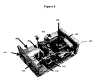
- a laser emits optical signals through a collimator 410 which collimates the beam for subsequent transmission through a laser aperture 405.
- Power is supplied to the unit by battery 480.
- the system further comprises a HV supply 430, an analog board 440, an APD receiver module 450, a receiver lens and filter assembly 460 and a receiver aperture 470 into which reflected optical signals are received.
- the resulting range is depicted on a range display 420.
- Laser system 100 of Figure 1 may be built as stand alone hand held units or embodied in larger systems.
- the laser system may be incorporated into tanks, planes, vehicles, armored trucks, carrying cases, backpacks, hand-held weapons, guns, and other devices.
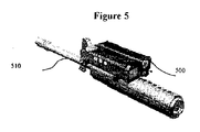
- Figure 5 shows a MOPA/EDFA based LRF system 500 mounted upon a shotgun barrel 510.
- the transmission pulse sequences s(t), stored in the memory module 155 are read out, using the counter 160, which is acted upon by the clock signal from the clock signal generator 165, and sent to the laser 110 causing the laser 110 to emit a pulse of light at time t0.
- This pulse of light is focused by the transmission optics 120 and travels to a target object 180 where it is reflected by a retroreflector/ obturator (not shown).
- the function of a retroreflector is to receive input electromagnetic energy and to reflect it back along the same or parallel path, preferably with similar general characteristics and preferably with relatively high gain and little spreading of the light beam.
- the receiving optics 130 collects a portion of the reflected light pulses and focuses them onto the light sensitive detector 140.
- the detector 140 converts the received light pulse into an electrical signal output at time t1 and amplifies the electrical signals, if necessary. These electrical signal outputs are supplied to the analog-to-digital converter 170 that generates corresponding sequence of digital values r(t) which are then stored in the memory module 155.
- the digital transmission and reception signals, s(t) and r(t) respectively, are communicated to the processor unit 175 which calculates and displays the range to the target object 180 based upon the time of flight of the laser pulse (t1-t0) and the speed of light c in the intervening medium.
- the counter 160 and the analog-to-digital converter 170 are acted on sychronously by the clock signal such that whenever a digital value s(t) from the memory module 155 is read-out and transmitted by the transmission optics 120, the analog value delivered at the same instant from the detector 140 is converted into a digital value r(t) and stored in the memory module 155. Consequently, after one transmission and reception cycle, signals of substantially the same shape are present in the memory module 155 wherein the received signal r(t) is shifted in time relative to the transmitted signal s(t) by the time of flight (t1-t0) along the path of measurement, corresponding to a specific number of clock cycles.
- the processor unit 175 derives the number of clock cycles corresponding to the time of flight (t1-t0) by calculating a correlation function k(t) between the transmission signals s(t) and the reception signals r(t), stored in the memory module 155.
- the correlation function k(t) values are calculated, in each case, by summing the products of oppositely disposed supporting position values of the two signals, s(t) and r(t) respectively.
- the maximum Kmax k(tmax) of the correlation function k(t) is determined where the tmax represents the time of flight at which the transmission and reception signals, s(t) and r(t), are time shifted relative to one another to an extent that their curves have a minimum spacing from one another or substantially overlap. This shift corresponds to the time of flight or the number of clock cycles that have elapsed between the transmission and reception signals s(t) and r(t) respectively. Since the reception signals r(t) are replicas of the transmission signals s(t) but delayed in time, persons of ordinary skill in the art would appreciate that the correlation operation between the two signals corresponds to a condition of autocorrelation.
- the sequence of digitized transmission pulses s(t), stored in the memory module 155 are of the recurrent pulse type that may be channel-coded using Barker binary codes, pseudo-random codes, Gold or Kasami code or any other suitable code known in the art.
- the transmission pulses s(t) are encoded using a Maximal Length Sequence (MLS), which is a family of pseudo random binary signals typically generated using a digital shift register whose input is generated from appropriate feedback taps.
- MLS Maximal Length Sequence
- the MLS code pulses may be pulse position modulated for data transmission.
- the MLS has suitable autocorrelation properties and since the signal takes values of +1 and -1, the autocorrelation may be computed using additions and subtractions, without the need for multiplications.
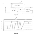
- Figure 2a shows an example of a MLS signal 240a generated by a four-stage shift register 200a that receives clock information from a clock source 210a and data.
- Alternative length sequences can be generated by using longer shift registers with appropriate feedback taps.
- Figure 3 shows a section from the calculated correlation function values k(t) between the transmission and reception signals s(t) and r(t) respectively.
- Five supporting values of the correlation function k(t) have been emphasized in Figure 3 , with the middle one of these five values representing the maximum tmax.
- the distance to the target object can be calculated from the determined t' max ; it is half the speed of light multiplied by the time-of-flight t' max .
- the calculated value of the time-of-flight t' max comprises the sum of the time-of-flight of light pulses transmitted and the signal transit time.
- the signal transit times represent measurement errors that can, for example, be eliminated by the use of a reference signal.
- a reference signal 105 as well as the reception signal r(t) 106 are shown as inputs to the changeover switch 185 for the selective coupling of the reference signal 105 and reception signal 106 to the correlator module 150.
- the changeover switch 185 has two switch positions, of which one is 'reference', associated with the reference signal 105 and the other is 'normal' associated with the reception signal 106.
- the reception signals r(t) 106 are correlated with the original transmission signals s(t) in the correlator module 150 to determine the time-of-flight t' max -However, when the switch position is 'reference', the reference signals 105 are correlated with the transmission signals s(t) in the correlator module 150 thereby determining the signal transit time error t error within the LRF system 100. This transit time error t error can then be subtracted from the time-of-flight value t' max for error correction.
- the present laser range finding system can also be used as an optical communication system.
- laser range finding systems employed lasers, such as YAG solid state lasers, having substantial recharge times, on the order of several milliseconds, in order to achieve the power levels required for effective laser range finding.
- lasers having very high pulse rates such as a MOPA/EDFA laser assembly, can be used to conduct laser range finding. Consequently, the same laser assembly can be used to generate the requisite pulse rate for data communications.
- the laser system as shown in Figure 1 , therefore employs a modulation scheme to modulate the optical signal.
- pulses are pulse position modulated for data transmission.
- a retroflector/obturator capable of rapid modulation is used.
- the present invention is not limited to a specific type of retroreflector/obturator and may employ any useful retroreflector device known in the art, such as, for example, a Tech SpecTM Corner Cube Retroreflector (Trihedral Prisms) available from Edmond Industrial Optics, Barrington, NJ.
- the obturator portion of retroreflector/obturator may include a mechanical shutter device capable of cycling open and closed within a few milliseconds, or more preferably, a liquid crystal device (LCD) disposed over the retroreflector portion, such as the LCD-CDS921 06 available from Cubic Defense Systems, San Diego, California.
- LCD liquid crystal device
- the selection of the retroreflector be tailored to the nature of the use. Specifically, the type of retroreflector used is largely dependent on the speed of the required modulation.
- Solid state devices for steering or high speed modulation of light use acousto-optic beam deflection, non-linear optical crystals, or optically pumped carrier shifting in semiconductors.
- Soft materials are preferably used as they offer the advantages of low power consumption and low cost processing methods such as ink jet deposition, micro contact printing, and self-assembly.
- Soft devices employ electro-optic polymers, liquid crystals, and micro-structured composites such as polymer-dispersed liquid crystals and nematic displays.
- Polymer dispersed liquid crystals operate on the principle of electrically controllable light scattering. These materials are combined application of polymers and liquid crystals, which do not require polarizers for its operation unlike nematic displays, thus making them more transparent with minimum loss of light.
- PDLCs consist of liquid crystal droplets that are dispersed in a solid polymer matrix.
- the resulting material is a polymer matrix with liquid crystal droplets filling in the holes.
- a fluid monomer epoxy resin
- fluid-curing agent hardener
- the mixture hardens (polymerizes) and locks in nearly spherical droplets of liquid crystal within the polymer binder.
- the arrangement of the liquid crystal molecules within these droplets depends primarily on the kind of polymer used and on the size of the droplet. Referring to Figure 6 , a schematic diagram of the polymer-dispersed liquid crystal cell is depicted.
- the polymer-dispersed liquid crystal cell comprises of two or more plates 601 stacked and separated from one another by means of liquid crystal 602 dispersed in a polymer matrix 603.
- the plates 601 can be of any transparent material including plastic and glass.
- the plates are coated with conducting and transparent electrodes 604.
- a closed state may occur when the liquid crystal molecules 702 are anchored with their long axes perpendicular to the droplet walls 703 with the point defect 704 in the centre of the droplet a radial configuration 701).
- a closed state may occur when the molecules are oriented perpendicular to the droplet wall 707, when there is weak surface anchoring (axial configuration 705). This configuration results in a line defect 711 that runs around the equator of the spherical droplet.
- an electric field (not shown) is applied to a radial droplet 701
- the molecules adopt the axial configuration 705.
- the radial configuration 701 is returned when the field is removed.
- a semi-open, semi-closed state may occur with a bipolar configuration 708, which is obtained by tangential anchoring of the liquid crystal molecules. This creates two point defects 709,710 at the poles of the droplet.
- the PDLC comprises of plurality of droplets 801,802,803 with different configurations and orientations i.e. the symmetry axes of these droplets are random. However, when an electric field 804 is applied the molecules within the droplets 801,802,803 align along the field 804 and have corresponding optical properties.
- the lines 805 on the droplet represent the directed orientation.
- Unpolarized light 806 entering the polymer-dispersed liquid crystal at normal incidence to the surface interacts with the droplets 801,802,803 oriented parallel and perpendicular to the incoming light, as well as angles in between. Since the symmetry axes are random, it is not possible for all the index of refractions to be similar. Due to the change in index of refraction as light traverses the crystal, the incoming light is scattered 807 by most droplets and the PDLC appears opaque. This property of polymer-dispersed liquid crystal is put to use while employing it as a shutter/obturator.
- the droplets 801,802,803 in the polymer-dispersed liquid crystal 800 rotate such that their symmetry axes are aligned parallel to the field.
- the ordinary index of refraction is matched to the refractive index of the matrix so that in a field ON state the light signals 806 experience the similar index of refractions that makes the crystal appear transparent and the light 807 is found at the other end of the crystal.
- the droplets 801,802,803 revert back to their random orientation and the display is again opaque.
- FIG. 9 is a functional block diagram of a polymer-dispersed liquid crystal as an obturator/modulator in use.
- the system comprises of a base station 901, a transceiver 902 for transmitting 903 and receiving 904 interrogation pulse, a remote station 905, an electronic driver 906 and a polymer dispersed liquid crystal 907.
- the turn-on or switch-on time is influenced by the applied voltage level and by the thickness of the liquid crystal layer.
- the voltage levels are preferably in the range of CMOS voltages.
- the retroreflector 908 is arranged behind the liquid crystal modulator 907.
- the polymer-dispersed liquid crystal 907 maintains the bistable state of ON and OFF and acts as an obturator for interrogation pulse stream 903 by blocking and allowing laser signals to pass through the crystal 907.
- the shuttering of the polymer-dispersed liquid crystal is controlled by the obturator signal provided by the electronic driver 906 capable of delivering voltages corresponding to the input signal 908.
- the input signal can be any pulse signal preferably pulse position or pulse width pulses.
- the incoming laser signals 903 are scattered strongly. Due to immense scattering the laser signals are not able to reach retroreflector 908 and it does not become effective.
- the cell 907 becomes transparent and the laser signals 903 are able to pass through it. Between the two states a preferably nearly linear section exists, which is used for the modulation of the laser signals 903. Furthermore, if one liquid crystal cell 907 is not sufficient to achieve a high depth of modulation, then a plurality of such cells 907 may be arranged in a row behind one another.
- ferro liquid crystals can be used as obturator/modulator to achieve faster data rates.
- FLCs have faster switching speeds than other types of liquid crystals and are used to make optical shutters and switchers (fast modulation of intensity of transmitted or reflected light as well as the polarization state of light).
- Spatial light modulators are also fabricated from FLCs, which provide the basis for advanced display technologies (high resolution, wide viewing angle, low driving voltage).
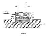
- FIG. 10 a cross-sectional view of the ferroelectric liquid crystal retroreflector to be used in the present invention is depicted.
- This device uses a dynamic memory on a very large scale integration (VLSI) backplane to activate the liquid crystal modulator wherein the FLC layer 1007 is sandwiched between the backplane 1008 and a cover glass 1002.
- VLSI very large scale integration
- a transparent and conductive indium oxide (ITO) layer 1001 is deposited on the undersurface of the cover glass 1002. This surface is then coated with an alignment layer 1003.
- a preferred alignment material is polybutylene teraphthalate (PBT).
- PBT polybutylene teraphthalate
- a metallic electrode 1005 with an electrode wire 1004 is mechanically bonded to the cover glass 1002. This metallic electrode 1005 is also electrically connected to the ITO layer 1001 to produce a transparent top electrode.
- the ferroelectric liquid crystal (FLC) layer 1007 is placed within a SiO spacer 1006 between the top electrode and the VLSI chip 1008.
- the VLSI backplane consists of a two-dimensional array of conductive pads acting as electrodes to apply voltage across the FLC layer.
- the conductive pads also serve as mirrors that output the modulated signal by reflection, since the VLSI backplane is non-transmissive.
- Each pad is electrically connected to an independent dynamic memory cell within the VLSI chip.
- Each memory cell stores a binary bit of data (i.e., 1 or 0) received from the obturator driver (not shown) in the form of voltages.
- a nonlinear FLC material acts as a half- wave retarder.
- a half-wave retarder rotates the light's polarization by 2[phgr], where [phgr] is the angle between the light's polarization and the waveplate's optic axis.
- the polarization of the incident/interrogation beam 1009 is rotated by twice the tilt angle ([PSgr]) of the optic axis. For example, if the FLC's optic axis tilts .+-.22 degrees about the smectic layer normal orientation, the net change of 4.4 degrees in the optic axis will rotate the light's polarization by 88 degrees.
- Rotation of the FLC material's optic axis (which is controlled by the direction of the electric field) produces a change in the light's polarization.
- This change in polarization can be converted to amplitude or phase modulation depending on the orientation of the FLC layer with respect to the polarization of the incident/ interrogation beam 1009.
- the modulated beam 1010 is then received by the interrogating device for identification and range finding.
- a micro-electro-mechanical system (MEMS) device is used as obturator/modulator.
- the Micro-Electro-Mechanical System integrates mechanical elements, sensors, actuators, and electronics on a common silicon substrate through microfabrication technology. While the electronic devices are fabricated using integrated circuit (IC) process sequences (e.g., CMOS, Bipolar, or BICMOS processes), the micromechanical components are fabricated using compatible "micromachining” processes that selectively etch away parts of the silicon wafer or add new structural layers to form the mechanical and electromechanical devices.
- IC integrated circuit
- Figure 11 depicts an arrangement of a MEMS device. It comprises of a base 1101, electrodes 1102, micromirrors 1103, and an insulator 1104.
- the base is preferably made of silicon. Between each electrode is a piece of silicon oxide, which serves as an insulator 1104 and the base for micromirror 1103.
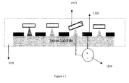
- Figure 12 depicts an arrangement of the above MEMS device when an electric field is applied.
- the electrodes 1202 direct the micromirrors 1203.
- a voltage 1204 is applied to the electrode 1202
- the electric field developed between the micromirror 1203 and electrode 1202 results in the movement of the micromirror 1203.
- the deflection of mirrors is a few degrees.
- the micromirror 1203 reflects incident light into or out of the MEMS device 1201.
- each micromirror 1203 can modify an optical beam into a modulated light stream, each micromirror 1203 forming obturators capable of selective activation or deactivation.
- the micromirrors 1203 are attached by the means of any elastic fastening known to those of ordinary skill in the art to enable resisting rotation away from a predetermined rest position and to selectively control the rotation thereof away from rest position.
- Micromirrors 1203 are generally placed in the optical paths of light pulses (not shown) in order to interrupt or modify light paths in accordance with their positions.
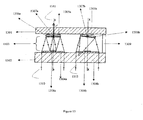
- FIG. 13 shows an exemplary embodiment of MEMS working as an obturator/modulator.
- the MEMS consists of input 1301 and output 1302 transparent plates and a wafer 1303 forming a substrate between the plates.
- Convergent focusing lenses 1304a and 1304b, electrodes 1305a and 1305b, micromirrors 1306a and 1306b, diaphragm 1307a and 1307b, and supplementary reflecting surface 1308a and 1308b are micro machined units of the wafer 1303.
- Frame 1309 forms a spacer surrounding the network of micromirrrors 1306 and maintains a defined distance between the output plate 1302 and wafer 1303.
- the MEMS In operation, when no voltage is applied the MEMS is in non-activated state.
- the incident light 1310 being initially focused by convergent focusing lens 1304a, is sent backwards by the reflecting surface of the micromirror 1306a, then reflected forwardly by the supplementary reflecting surface 1308a and finally sent towards the exterior through the diaphragm 1307a to act as modulated light beam 1311.
- the MEMS device when voltage is applied, the MEMS device is in activated state. Due to application of voltage the micromirror 1306b is turned through a small angle. The activated configuration leads to a deflection in the light beam 1312, initially focused by the convergent focusing lens 1304b and sent back by the reflecting surface present on the micromirror 1306b, outside the field associated with the supplementary reflecting surface 1308b. The latter is thus not in a position to cause the passage of the light through the diaphragm 1307b, and, as a result, shuttering takes place.
- the present optical communication system uses pulse position or pulse width modulation to control the operation of the electronic driver connected to MEMS.
- Each data bit in the obturator driver results in the obturator signal/voltage to provide the activation-deactivation voltages.
- the control voltages make the MEMS to shutter the interrogation pulse stream passing through it.
- the mirror is turned ON during the bit period and light in the form of interrogation pulse stream is shuttered during this period. If the bit is not active the mirror is turned OFF and the light enters the MEMS to produce the modulated response pulse stream to the source for identification and range finding.
- multiple quantum wells can also be used as retro reflectors wherever there is need for fast data rates.
- Multiple quantum wells are semiconductor structures composed of alternating thin layers of two or more different semiconductor materials and, in particular, of semiconductor materials having differing bandgaps for example, GaAs, AlGaAs, and InGaAs among others.
- MQW structures are usually produced using well-known epitaxy techniques, such as molecular beam epitaxy or metal-organic chemical vapor deposition sometimes known as organometallic vapor phase epitaxy.
- layer thickness is of the order 100 Angstroms and a typical structure might comprise 100 such layers, resulting in a total thickness of about 1 micrometer.
- the advantage of the MQW device technology for an optical communication system is that it operates on low power and can provide fast modulation rates.
- the maximum speed of a MQW modulator is determined, up to THz rate, by the RC time constant of the device and its driver.
- speed of about 10 MHz is possible with a square centimeter aperture device.
- the optical modulators using MQW can be designed to be rugged and lightweight.
- MQW technology By coupling MQW technology with optical communications system, optical transceiver for secure, high speed data transmission can be produced. These devices require very low power and are less likely to interfere with the surrounding equipment than other devices. MQW devices are generally compact, low mass, rugged and environmentally stable. Conventional electronic circuit, such as TTL logic, can power these devices. These characteristics make these devices suitable for remote data transmission from sensitive or high value platforms, such as satellites and unpiloted airborne vehicles.
- the Base station transmitter 1401 transmits an interrogation signal 1403 to a remote object 1402.
- the interrogation signal 1403 passes through MQW modulator 1404 controlled by an electronic driver 1405, which impart voltages across MQW modulator 1404 corresponding to input signal 1406. These voltages cause MQW modulator 1404 to shutter the interrogation light passing through it, resulting in a modulated interrogation beam 1407 and is then reflected back.
- the selection of the retroreflector is largely dependent on the nature of use and rate of modulation required. For example, as we move from PDLC to FLC to MEMS to Quantum Well, the modulation rate keeps on increasing and it ranges from 1 KHz in case of PDLC to 1GHz in Quantum Wells.
- the optical retroreflectors may be temperature stabilized with a thermoelectric cooler and/or a resistive heater to optimize the contrast ratio for a given operating environment.
- a bias voltage may be applied to the device and adjusted to compensate for temperature changes by a small battery delivering the required power.
- the time taken to heat the crystal is approximately 0 .9 milliseconds.
- a PDLC is used in an environment having an ambient temperature at or below 20 degrees Celsius.
- the heating is preferably done only when the device, or the user operating the device, recognizes that an incoming communication signal has been recognized and a communication channel needs to be established. For example, in a secure covert operation, as described below, the heating element will activate after an initial transmit signal is positively identified by a response unit. Upon such recognition, the optical retroreflector will activate the PDLC heater in order to warm the PDLC unit up, if the temperature is below 20 degrees Celsius.
- the heater can take 10 to 60 ms to bring the temperature of the PDLC up to the point that it can effectively operate in the required response time, it is preferred to have the transmit signal repeat several times, thereby being ready to correctly modulate the response pulses in subsequent transmissions.
- a heating element is integrated with retroreflectors of the present invention.
- a user activates the heating element, to prepare for a known optical transmission.
- an optical transmission can include an initial interrogator message acting as a wakeup message.
- the wakeup message causes the heating element to be activated, i.e. a voltage source, and for heat to be applied to the retroreflector, i.e. by subjecting it to a bias voltage.
- the rapid heating process preferably taking less than a few milliseconds, enables improved operational performance, thereby allowing the system to work substantially optimally even if the temperature drops below a certain threshold level.
- the retroreflector and range finding system can be exploited in an assortment of applications including, ground to air, ground to space, air to air, air to space and space to space data transmission, and, more specifically but not limited to, secure covert operations, microsatellites, dynamic optical tags (DOTs), and tetra hertz operational reachback (THOR).
- DOTs dynamic optical tags
- THOR tetra hertz operational reachback
- One embodiment of the present invention is directed toward a secure covert operation for combat comprising a combat response unit having a helmet-mounted challenge receiver and a retroreflector/obturator, including the steps of projecting a high pulse laser signal and a transmitted code of the day (TCOD) onto the combat response unit from a combat interrogatory unit, receiving the laser transmit signal and TCOD at the challenge receiver, selectively reflecting the laser transmit signal by opening and closing the retroreflector/obturator according to a response code of the day (RCOD), receiving the reflected laser transmit signal and RCOD at the combat interrogatory unit, and combining the received RCOD with the TCOD to identify the combat response unit and its position.
- the present invention can be used, therefore, to conduct laser range finding, perform code transmissions, and conduct voice communications.
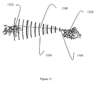
- FIG. 15 illustrates the operation of the combat identification system of this invention.
- the combat interrogatory unit 1520 of this invention is shown in a preferred weapon-mounted disposition where the challenging soldier may target the helmet-mounted combat response unit 1522 of this invention worn by a soldier in a combat simulation exercise or in actual combat.
- the response unit 1522 could be mounted in any location proximate to or on the soldier, including a vest, belt harness, or other device. Further one of ordinary skill in the art would appreciate that the response unit 1522 could be mounted to an object, such as a tank, building, conventional transceiver, vehicle, plane, or other structure.
- An infrared (IR) transmit signal 1524 is projected by unit 1520 upon operator command. Transmit signal 1520 radiates outward along a narrow beam, eventually illuminating response unit 1522.
- transmit signal 1524 may be embodied as a 6 milliradian beam of 1540 nm IR light, which then illuminates an area of about 6 meters on a side at a typical weapon range limit of 1000 meters.
- transmit signal 1524 is then retroreflected back to interrogatory unit 1520 as the response signal 1526.
- response signal 1526 includes a reflection of, for example, a 1.5 centimeter portion of the 6 meter transmit beam 24.
- This 1.5 cm reflected portion includes about 0.002 percent (-47 dB) of the initial energy of transmit signal 24, which is generally reflected back to interrogatory unit 20 by a precision retroreflector.
- Response signal 1526 is received at interrogatory unit 1520 reduced by an additional -8 dB, which leaves sufficient power for combat personnel detection and processing at interrogatory unit 1520.
- the 1540 nm signal wavelength is preferred because it is eye-safe and has relatively low absorption and scattering loss in the usual battlefield smoke and haze.
- the user can choose to use the signal in order to determine the range of a combatant, tank, building, truck, vehicle, or other object, as previously discussed, or as a mechanism to communicate important information, including but not limited to, code identifications, such as whether the individual is a "friend” or "foe, and audio communications.
- transmit signal 24 includes a transmit code of the day (TCOD) including a frame-synchronization preamble (not shown) followed by a TCOD 24(a) followed by a TCOD interrogation pulse stream 24(b).
- TCOD 24(a) is received by one or more of the plurality of IR sensors 30 and presented to the challenge receiver 46 for verification.
- challenge receiver 46 produces a response code of the day (RCOD) signal 48, which includes a logical combination of selected information from TCOD 24(a) and from the local memory of challenge receiver 46 (not showm) that is described in detail hereinbelow.
- RCOD signal 48 is presented to the obturator driver 50, which produces an obturator signal 52 for opening and closing (making translucent and opaque) the obturator 54 in each of the plurality of retroreflector/ obturators 32.
- the present invention is not operable, nor are the related algorithms or source codes available, through reverse engineering in an instrumented lab. If an embodiment of the present invention could be made operable by an individual who is not authorized to operate the device or if that unauthorized individual could access the methods and/or codes used to drive the device, the security of the system would be compromised.
- the system uses narrow laser beams for bi-directional communications; a secret rolling code of the day that changes over a pre-designated time period and is only known to authorized persons; a randomly generated number that is known to the interrogator and receiver; processes that utilize encryption of the COD by the RGN in both directions; identification methods, such as fingerprints, voice, or manual keying, to determine if an authorized person is using the weapon; hardware with a secure area; and self-destruct mechanisms to destroy software and codes upon deconstruction of the device.
- a biometric identification (ID) signal 56 is also presented to obturator driver 50 to enable or disable operation thereof based on the verification of a scanned thumbprint input by the dismounted soldier in possession of helmet-mounted response unit 22, which is further described hereinbelow in connection with Figs. 17 and 20 (a) - (d) .
- RCOD signal 48 includes a delay and a response pulse stream 26(a). The RCOD delay is sufficient to permit TCOD interrogation pulse stream 24 (b) to arrive at reflector/obturator 32.
- Obturator 54 is then cycled open and closed in accordance with obturator signal 52 to produce response pulse stream 26(a) by reflecting selected elements of interrogation pulse stream 24(b) from the retroreflector 58 in at least one of the plurality of retroreflector/obturators 32.
- identification measures could be used to insure the operator of the response unit or interrogator unit are authorized users, including the user's voice pattern, or a keyed in verification input, i.e. a password.
- a transceiver integrated with a memory and processor could be used to recognize an authorized voice pattern. If a received audio input matches a stored pattern, the processor communicates a positive signal 58 back to the to obturator driver 50.
- a keypad in data communication with a memory and processor could be used to receive a data input from a user. If the data input matches an authorization code stored in the memory, the processor communicates a positive signal 58 back to the to obturator driver 50.
- the identification measures could optionally be subject to a timer that requires the user to periodically demonstrate that he or she is, in fact, an authorized user.
- the timer is programmed to activate a verification process on a periodic basis, such as once every 24 hours.
- the verification process requires a user to input identification data, such as biometric or personal data, into the unit or indicate activity, i.e. through motion, via motion sensors. Entering this verification information in time will ensure the unit retains the codes used to generate the transmit signal. Failure to enter this information in time will cause the unit to turn off the use of codes or possibly destroy the existence of codes under the assumption that the unit has fallen outside of the possession of an authorized user and must therefore be stripped of its codes.
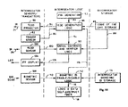
- Fig. 17 is a schematic diagram illustrating the logical operation of a response unit.
- the elements of Fig. 17 are arranged in three functional categories for clarity; (a) helmet sensors, (b) helmet logic and (c) helmet memory.
- helmet-mounted response unit is first programmed with certain biometric data unique to the user and with a code of the day (COD), which includes a challenge code (CC) followed by a response code (RC).
- COD code of the day
- RC response code
- the helmet is then donned by the user according to a predetermined anti-spoofing protocol.
- the donning soldier first passes his/her thumb over a biometric thumbprint sensor 60 in a manner (known only to the soldier) for which response unit 22 has previously been programmed.
- Biometric thumbprint sensor 60 produces the coded biometric data stream 62, which is immediately evaluated by the biometric identification logic 64. This evaluation involves comparing data stream 62 to the earlier-stored thumbprint scan data 66 for the donning soldier to produce an enable/disable decision. If logic 64 decides that the thumbprint scan fails, the soldier may be afforded, for example, two additional opportunities to enable the helmet-mounted response unit by means of an audible or visual indicator (not shown). After two additional attempts, logic 64 decides that the biometric ID is invalid, and sets biometric ID signal 56 to "disable" obturator driver 50, permanently shutting obturator 54 to prevent any retroreflection.
- biometric ID signal 56 may also be presented to a self-destruct timer 67, which begins a logic and memory self-destruction count-down. When completed, this countdown triggers the erasure of all logic and data stored in the helmet memory, thereby making a captured helmet-mounted response unit worthless to an enemy.
- the helmet electronics may easily be reprogrammed by the friendly forces for use in another combat exercise or the like.
- biometric ID signal 56 is set to "enable” and obturator driver 50 is enabled so the soldier is thereafter equipped to passively respond to valid incoming interrogatory signals in the manner now described.
- the helmet-doffing sensor 68 immediately signals logic 64, which resets biometric ID signal 56 to "disable” and obturator driver 50 is again disabled, permanently shutting obturator 54 to prevent any retroreflection.
- a response unit first begins the secure covert communication upon the arrival of IR transmit signal 24 from interrogatory unit 20.
- TCOD 24(a) is received by at least one IR sensor 30, which produces a signal 70 that is presented to the signal verification and decoding logic 72.
- the relative location on the helmet of the particular IR sensor 30 receiving the signal is identified in logic 72 to determine the arrival quadrant (Front, Right, Rear, or Left) of IR transmit signal 24.
- This arrival quadrant information may be used in logic 72, for example, to bias other processing parameters or to signal the helmeted soldier, by audible or visual means, of the arrival quadrant so that appropriate action may be undertaken (such as, for example, ashamed evasion of interrogatories arriving from behind enemy lines).
- TCOD 24 (a) is validated by examining it to verify that it includes a valid CC followed by a randomly generated number (RGN). This is accomplished by comparing the received CC with the CC portion of the COD 74 stored in the helmet and accepting the RGN if the incoming CC matches the stored Cc. The entire stored COD 74 and the incoming RGN are then passed as a data signal 76 to the response code of the day (RCOD) generation logic 78, which creates the RCOD 80 by combining the CC and RC portions of the stored COD with the PRN in a predetermined manner. After generation, RCOD 80 is passed to obturator driver 50 for use in opening and shutting obturator 54 accordingly.
- RGN randomly generated number
- the first portion of RCOD 80 is a closed shutter interval that is computed as a combination of the stored RC and the incoming RGN.
- the second portion of RCOD 80 is an open-shutter interval that is determined by some portion of the CC.
- RCOD 80 is synchronized to begin at a predetermined interval (such as 10 ms) after the end of the incoming TCOD so that the interrogator may evaluate RCOD 80 to verify that the reflecting response unit is a mend and not a foe, thereby completing the IFF transaction.
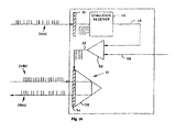
- Fig. 18 is a schematic diagram illustrating the logical operation of interrogatory unit.
- the elements of Fig. 18 are arranged in three functional categories for clarity; (a) interrogator sensors/emitters, (b) interrogator logic and (c) interrogator memory.
- an interrogatory unit first begins the secure covert communication when the trigger sensor 82 detects a command from the operator to interrogate a target.
- Trigger sensor 82 produces a signal 84 that is presented to the TCOD generation logic 86, which responsively retrieves a locally-stored copy of the COD 88 and a RGN 90 from a pseudorandom number (PRN) generator 92.
- PRN pseudorandom number
- TCOD generation logic 86 then combines the CC portion of COD 88 with RGN 90 to produce the TCOD portion of TCOD 94, which is then followed by the TCOD interrogation pulse stream.
- TCOD 94 is then amplified as necessary to drive the TCOD projector 96, which produces the IR transmit signal 24, initiated with the frame-synchronization preamble (not shown), and directs it to the target.
- TCOD is also presented to the signal decoder and verifier logic 98 for use in processing any incoming IR signals received at the IR sensor 100.
- logic 86 notifies logic 98 of the start of the response interval. Any incoming response signal 26 at RCOD sensor 100 produces a RCOD signal 102 that is presented to logic 98 for evaluation.
- Logic 98 reverses the encoding process discussed above in connection with Fig. 17 and below in connection with Fig. 19 .
- RGN 90 and the RC from COD 88 are used to compute the proper closed-shutter interval, which is compared to the delay interval between completion of the transmission of TCOD 94 and the beginning of response pulse stream 26(a).
- the appropriate elements of COD 88 are then used to compute the proper open shutter interval, which is then compared to the actual length of the incoming response pulse stream 26(a). If the two comparisons are not successful, logic 98 does nothing; leaving the display 104 inactive. When the comparisons are both successful, logic 98 produces an indicator signal 106, which activates display 104, thereby completing the transaction.
- Display 104 may be a simple light-emitting diode (LED) indicator or an audible signal or any other useful indicator consistent with requirements for security and covertness.
- an interrogatory unit may also include anti-spoofing means to prevent use by an enemy of a captured interrogatory unit.
- a biometric sensor 108 may be used to accept thumbprint or fingerprint input or retinal image input or any other useful biometric data unique to the authorized operator. Upon activation, biometric sensor 108 presents the incoming biometric data 110 to the biometric ID logic 112 for comparison to the biometric ID data 114 stored previously by the same soldier. If, at some point, logic 112 decides that the biometric ID is invalid, a biometric ID signal 116 is set to "disable" and TCOD generator logic 86 is disabled, permanently shutting down TCOD projector 96.
- biometric ID signal 116 may also be presented to a self-destruct timer 118, which begins a logic and memory self-destruction countdown. When completed, this countdown triggers the erasure of all logic and data stored in the interrogator memory, thereby making a captured weapon-mounted interrogatory unit worthless to an enemy.
- the interrogator electronics may easily be reprogrammed by friendly forces for use in another combat exercise or the like.
- biometric ID signal 116 is set to "enable” and TCOD generator logic 86 is enabled so the soldier is thereafter equipped to actively interrogate targets in the manner described above.
- TCOD generator logic 86 After a predetermined period of inactivity, established by, for example, a simple timer (not shown), logic 116 resets biometric ID signal 116 to "disable” and TCOD generator logic 86 is again disabled, permanently shutting down TCOD projector 96.
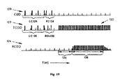
- Fig. 19 is a chart illustrating the relationship between exemplary embodiments of the COD 120, the TCOD 122 and the RCOD 124 of this invention.
- Each of the six symbols of COD 120 and TCOD 122 are 7-bit values (ranging from 0-127) encoded as pulse positions within a 36 microsecond frame interval, which is established and synchronized for each transaction by a three-pulse TCOD frame-synchronization preamble (not shown).
- Each pulse is 66.67 ns in duration, which allows the use of an inexpensive microprocessor (not shown) for implementing the various logic described herein.
- COD 120 is changed daily and all interrogatory units and response units in a system are updated daily with the new COD 120.
- COD 120 includes a 4-symbol CC 126 and a 2 symbol RC 128.
- TCOD 122 includes CC 126 and a 2 symbol RGN 130 followed by a 10-ms buffer interval followed by TCOD interrogation pulse stream 132 consisting of a 50 ms stream of I-ms spaced pulses.
- RCOD 124 includes a delay 134 during the closed-shutter interval followed by a response pulse stream 136 during the open shutter interval.
- Delay 134 is computed by dividing the absolute value of the difference between RGN 130 and RC 128 by ten and adding 10 ms, providing a range of values from 10-20 ms in 1 ms steps.
- This coding method is both secure and covert because RGN 130 is shared only by the interrogator and target even though COD 120 is known by all friendlies.
- interception of RGN 130 is unlikely because of the narrow TCOD beam (3 milliradians), any such interception is useless without prior knowledge of COD 120 because RC 128 is not transmitted and both RC 128 and RGN 130 are required to compute delay 134.
- the open shutter interval that reflects response pulse stream 136 is computed in milliseconds by adding three times the fourth digit of CC to five, giving a range of values from 5 to 32 ms in 3 ms steps.
- the duration of response pulse stream 136 cannot be spoofed without prior knowledge of COD 120 or interception of TCOD 122 and the duration of delay 134 cannot be spoofed without having both the prior knowledge of COD 120 and the successful interception of TCCD 122.
- Such spoofing also presumes prior knowledge of the decoding algorithms described above.
- Each transaction is completed within 60 ms.
- An interrogator may repeat an interrogation as desired to reduce the probability of false negatives. Assuming that interrogation is repeated up to four times before accepting a negative (partial response) result, the entire transaction is completed within 250 ms. This method of obtaining a response is necessary only under extreme scintillation and range conditions, at the limits of link performance.
- Figs. 20(a)-(d) show several examples of suitable means for accepting biometric data for helmet-mounted response unit.
- One suitable device for accepting biometric fingerprint or thumbprint data is the FCD4B14 FingerChipTM available From AtMel Corporation, San Jose, CA.
- the print sensor 138 is disposed such that a finger 140 may be drawn across print sensor 138 while in continuous contact therewith. Continuous contact is important and is facilitated by providing a curved surface 142 generally as shown.
- a stream of digital biometric data is produced by print sensor 138 and presented on a data bus (not shown) for manipulation by microprocessor-controlled logic (not shown).
- biometric data stream depends not only on the fingerprint but on the direction and manner in which finger 140 is drawn across print sensor 138. This is an important feature of this invention because it adds considerable security to helmet-mounted response unit in that the availability of the proper finger or thumb alone is insufficient to satisfy the biometric security requirement; the user must also recall and repeat with reasonable accuracy the exact manner in which the thumb or finger was drawn across print sensor 138 when first storing the user's biometric ID data in response unit.
- Fig. 20(b) shows another mounting arrangement suitable for print sensor 138, although the curved surface 142 is preferable.
- Fig. 20(c) shows yet another example employing the curved surface 144, which importantly permits continuous contact between finger 140 and print sensor 138 while moving thereover.
- Fig. 20(d) demonstrates an exemplary arrangement for placing print sensor 138 within helmet-mounted response unit so that the user may draw the thumb 146 over print sensor 138 while grasping helmet-mounted response unit 22 preparatory to donning same.
- Any useful audio and/or visual indicator means may be provided to inform the user that helmet-mounted response unit has been successfully activated, thereby affording the opportunity to retry activation by repeating the movement of thumb 146 across print sensor 138. If desired, repeated attempts may be accumulated against a limited number followed by self-destruction of all logic and data stored in helmet-mounted response unit.
- biometric data necessary to identify several members of a combat unit may be stored in biometric ID storage 66 so that any combat unit member may activate a helmet-mounted response unit.
- biometric ID storage 66 This permits a member of the combat unit to "borrow" the helmet and its response unit from another member of the same combat unit and successfully activate it for use in the battlefield.
- the size of the group of authorized users is limited only by the memory available in biometric ID storage 66, which may be loaded by mass-transfer of digital data collected from the thumb-scans of all members of the combat unit.
- biometric data necessary to identify several members of a combat unit maybe stored in biometric ID storage 114 thereby permitting a member of the combat unit to "borrow" the weapon and response unit from another member of the same combat unit and successfully activate it for use in the battlefield.
- Fig. 21 is a block diagram showing a flow chart exemplifying the covert communication transaction method of this invention.
- This process begins with the step 148 where the interrogating soldier triggers an interrogation command at an interrogatory unit.
- a TCOD is created by accepting the RGN produced in the step 152 and the COD retrieved from local memory in the step 154.
- an IR transmit signal encoding the TCOD is projected to the targeted response unit.
- the TCOD is received at the targeted helmet-mounted response unit.
- step 158 the 3-pulse frame-synch preamble and the first six symbols of the TCOD are first received and decoded in step 158, which may also include an arrival quadrant indication step (not shown) to notify the helmet wearer by some useful means of the quadrant (Front, Right, Rear, or Left) from which the received TCOD has arrived.
- arrival quadrant indication step not shown
- the received TCOD is validated by first verifying that the biometric security has been satisfied in the step 162 and then retrieving from local storage the COD in the step 164.
- the CC (the first four symbols from the COD) is compared with the CC from the received TCOD and, if matched, the next two symbols of the received TCOD are decoded as the RGN in the step 166.
- the RGN From step 166 and the RC (the fifth and sixth symbols of the COD) are used to compute the closed shutter interval (the delay interval) of the RCOD and the fourth symbol of the COD is used to compute the open shutter interval (the response pulse stream) of the RCOD.
- the RCOD from step 168 is used to cycle the obturator, thereby retroreflecting the interrogatory pulse stream portion of the TCOD according to the RCOD.
- the RCOD is received and decoded at the interrogatory unit and validated in the step 174, which uses the locally-stored RGN and COD retrieved in the step 176 to duplicate thy computations used to create the RCOD at the response unit and to compare the received RCOD with the locally-computed RCOD.
- the results of step 174 are evaluated to make a friend or foe decision, completing the transaction initiated in step 148. If Friend, then the step 180 signals the interrogatory unit user in some useful manner, such as lighting up an LED for a short time. If Foe, then the step 182 initiates a repetition of the transaction (with a new RGN) or does nothing, thereby indicating that the transaction has failed to identify a friend.
- Such data can include, but is not limited to, audio, text, and/or images.
- DOT dynamic optical tags
- DAS dynamic optical tags
- a DOT is preferably a small, thin, environmentally robust, long lived, modulated optical retro-reflecting tag working in conjunction with a long range interrogation system.
- DOTs are passive (i.e. in the sleep mode) and are only activated when interrogated.
- a DOT modulates an illuminating beam to transmit coded information onto a retro-reflecting path.
- a DOT is non-RF to avoid depending upon radio frequencies that can be detected by the tagged target or by third parties in the area of the emitter.
- a DOT When affixed to an object, a DOT provides a tracking entity the ability to uniquely identify and locate the object. As the object on which the tag is mounted moves through a region, the DOT can record location information (via a global positioning satellite receiver), imagery, temperature, pressure, audio, and other data that can provide information about the object, the conditions under which it was subjected, its location and its state.
- a DOT is a retroflector/obturator capable of rapid modulation is used, such as a Tech SpecTM Corner Cube Retroreflector (Trihedral Prisms) available from Edmond Industrial Optics, Barrington, NJ.
- the obturator portion of retroreflector/obturator may include a mechanical shutter device capable of cycling open and closed within a few milliseconds, or more preferably, a liquid crystal device (LCD) disposed over the retroreflector portion, such as the LCD-CDS921 06 available from Cubic Defense Systems, San Diego, California.
- LCD liquid crystal device
- a DOT can comprise of a base station 901, a transceiver 902 for transmitting 903 and receiving 904 interrogation pulse, a remote station 905, an electronic driver 906 and a polymer dispersed liquid crystal 907.
- the turn-on or switch-on time is influenced by the applied voltage level and by the thickness of the liquid crystal layer.
- the voltage levels are preferably in the range of CMOS voltages.
- the retroreflector 908 is arranged behind the liquid crystal modulator 907.
- the polymer-dispersed liquid crystal 907 as mentioned above maintains the bistable state of ON and OFF and acts as an obturator for interrogation pulse stream 903 by blocking and allowing laser signals to pass through the crystal 907.
- the shuttering of the polymer-dispersed liquid crystal is controlled by the obturator signal provided by the electronic driver 906 capable of delivering voltages corresponding to the input signal 908.
- the input signal can be any pulse signal preferably pulse position or pulse width pulses.
- a DOT used in the present invention is not larger than 25mm x 25mm x 5mm; operates in an environment ranging from minus 70 Celsius to 45 degrees Celsius; has an angle of regard of plus or minus 60 degees or greater; and modulates at least 100 kbits/sec.
- a heating element as previously described, could be incorporated to enable effective operation of the liquid-crystal system.
- the system 100 comprises a laser 110, an optical transmitter 120, an optical receiver 130, a light sensitive detector 140, a change-over and a correlator module 150.
- the correlator module 150 further comprises a clock signal generator 165 that provides working clock signals to an analog-to-digital converter 170, a counter 160 for addressing and sequencing a memory module 155 and a processing unit 175.
- the memory module 155 stores digitized values of a sequence of transmission pulses s(t), for triggering the laser 110, as well as reception pulses r(t) outputted from the detector 140 and digitized by the analog-to-digital converter 170.
- a laser emits optical signals through a collimator 410 which collimates the beam for subsequent transmission through a laser aperture 405.
- Power is supplied to the unit by battery 480.
- the system further comprises a HV supply 430, an analog board 440, an APD receiver module 450, a receiver lens and filter assembly 460 and a receiver aperture 470 into which reflected optical signals are received.
- the resulting range is depicted on a range display 420.
- an aircraft is tracking a tagged cargo container and a tagged tank.
- a tag is placed on both the container and tank.
- the tag is a modulating dynamic optical tag that is small, thin and retroreflecting.
- the tag remains in passive mode (sleep mode) for most of its operation and it is activated when interrogated by a high pulse laser beam, preferably emitted from the tracking aircraft.
- the tag then starts modulating the illuminating beam to transmit coded information, such as stored data detailing temperature, time, pressure, movement, location, and other characteristics, on the retro-reflecting path for identification and range finding in accordance with the principles of the present invention.
- the interrogator system then further transmits and/or displays acquired data, including range from the object, temperature, time, pressure, movement, location, and other characteristics.
- the interrogator system supports a communication range of 1 kilometer or greater, uses less than 800 watts of prime power, and weighs less than 25 kilograms. More preferably, an airborne interrogator supports greater than 10 Km range at communication rates greater than 100 Kbps.
- Dynamic Optical Tag enabled optical communication system of the present invention results in a small, thin, environmentally robust, modulated optical retro-reflecting tag and a long-range interrogation system. In addition, this enables highly precise tag location along with reliable and efficient information flow between the tags and the interrogation device operating in non-RF and visually non-alerting mode.
- Another embodiment of the present optical communications system may be applied to achieving the objectives of DARPA's Terra Hertz Operational Reachback, THOR, program, thereby overcoming the disadvantages of conventional communication systems.
- THOR attempts to create a mobile, free space, optical network having data transfer rates of 10 gigabits per second and an aircraft to aircraft link distance of approximately 400 kilometers.
- An optical communications system implementing THOR uses aerial optical transmissions to establish a link that extends from a terrestrial point of presence to an underwater vehicle via an aircraft or spacecraft surrogate with an air to air relay link so as to track target objects such as tanks, aircrafts, forces, ships, subsurface vehicles etc.
- target objects have the retroreflectors attached therewith.
- Interrogation signals from aircraft, preferably high pulse rate laser signals, are modulated-reflected by the retroreflector back to the aircraft for identification and range finding in accordance with the principle of the present invention.
- THOR unlike GPS systems, does not get jammed during warfare, clouds or turbulences.
Landscapes
- Physics & Mathematics (AREA)
- Engineering & Computer Science (AREA)
- Computer Networks & Wireless Communication (AREA)
- General Physics & Mathematics (AREA)
- Radar, Positioning & Navigation (AREA)
- Remote Sensing (AREA)
- Electromagnetism (AREA)
- Optics & Photonics (AREA)
- Signal Processing (AREA)
- Optical Radar Systems And Details Thereof (AREA)
- Optical Communication System (AREA)
Claims (30)
- Lasersystem (100) zum Ermitteln von Bereichswerten und Ermöglichen von Kommunikationen zwischen mehreren Parteien, welches umfasst:einen Laser (110) zum Erzeugen mehrerer Übertragungspulse als Reaktion auf eine von einem Datensignal modulierte Überträgungspulssequenz, wobei der Laser durch eine erste Partei aktiviert wird;ein optisches Übertragungssystem (120) zum Leiten der von dem Laser (110) emittierten Übertragungspulse weiter zu einem Zielobjekt (180), wobei die Übertragungspulse von dem Zielobjekt reflektiert werden, um reflektierte Signale zu erzeugen,ein optisches Empfangssystem (130) zum Empfangen der reflektierten Signale; und einen Prozessor (175) zum Ableiten von auf den reflektierten Signalen modulierten Bereichsdaten und Kommunikationsdaten aus den reflektierten Signalen, dadurch gekennzeichnet, dass:der Laser (110) so konfiguriert ist, dass er mehrere Übertragungspulse als Reaktion auf eine von dem Datensignal modulierte pseudozufällige kodierte Übertragungspulssequenz erzeugt.
- Lasersystem nach Anspruch 1, dadurch gekennzeichnet, dass die Kommunikationsdaten beliebige von: Audio-, Video-, Text- oder Bilddaten umfassen.
- Lasersystem nach Anspruch 1, dadurch gekennzeichnet, dass die optische Übertragung weiterhin einen Kollimator (410) umfasst.
- Lasersystem nach Anspruch 1, dadurch gekennzeichnet, dass der Laser (110) ein schnell gepulster Laser ist.
- Lasersystem nach Anspruch 4, dadurch gekennzeichnet, dass der Laser (110) ein beliebiger von: modengekoppelter titandotierter Saphirlaser für den sichtbaren Bereich, modengekoppelter Kerr-Linsen-Laser, polarisationsempfindlicher modengekoppelter Faserlaser oder aktiv modengekoppelter Laser ist.
- Lasersystem nach Anspruch 4, dadurch gekennzeichnet, dass die Laserquelle (110) eine Mutteroszillator-Leistungsverstärkervorrichtung ist.
- Lasersystem nach Anspruch 6, dadurch gekennzeichnet, dass die Laserquelle (110) weiterhin ein optisches Verstärkermedium umfasst.
- Lasersystem nach Anspruch 7, dadurch gekennzeichnet, dass das optische Verstärkermedium ein erbiumdotierter Faserverstärker ist.
- Läsersystem nach Anspruch 1, dadurch gekennzeichnet, dass das optische Empfangssystem weiterhin eine analoge Platte (440), ein APD-Empfängermodul (450), eine Empfangslinse, eine Filteranordnung (460) und eine Empfängeröffnung (470) umfasst, in die die reflektierten Signale empfangen werden.
- Lasersystem nach Anspruch 1, dadurch gekennzeichnet, dass Bereichsdaten auf einer Bereichsanzeige (420) angezeigt werden.
- Lasersystem nach Anspruch 1, welches weiterhin umfasst:einen lichtempfindlichen Detektor (140);ein Umschaltmodul (150); undein Korrelatormodul.
- Lasersystem nach Anspruch 11, dadurch gekennzeichnet, dass das Korrelatormodul (150) umfasst:einen Speicher (155) zum Speichern mehrerer kodierter Pulssequenzen zum Triggern des Lasers (110) und zum Speichern der reflektierten Signale, wobei die reflektierten Signale von einem mit dem Empfangssystem gekoppelten Analog-Digital-Wandler (170) digitalisiert werden; undeinen Prozessor (175) zum Berechnen eines Bereichs des Zielobjekts (180) durch Korrelieren der reflektieren Signale mit den übertragenen Pulsen und Schätzen einer Zeitverzögerung der reflektierten Signale, bei der die Korrelation zwischen den übertragenen Pulsen und reflektierten Signalen maximal ist.
- Lasersystem nach Anspruch 12, dadurch gekennzeichnet, dass der Prozessor (175) weiterhin die besten Ausgleichsgeraden für eine vorbestimmte Zahl von Abtastpunkten vor und nach einem maximalen Korrelationspunkt berechnet, um ein revidiertes Maximum zu berechnen.
- Lasersystem nach Anspruch 1, dadurch gekennzeichnet, dass der Laser (110) mehrere Übertragungspulse bei schnellen Raten erzeugt und dass der Laser durch kodierte Pulssequenzen, die aus einem Speicher bei einer vorbestimmten Taktfrequenz ausgelesen werden, getriggert wird.
- Lasersystem nach Anspruch 14, dadurch gekennzeichnet, dass die kodierte Pulssequenz zum Triggern des Lasers pseudozufälliger binärer Art ist.
- Lasersystem nach Anspruch 14, dadurch gekennzeichnet, dass die kodierte Pulssequenz zum Triggern des Lasers mit Hilfe einer Maximallängensequenz kodiert ist.
- Lasersystem nach Anspruch 1, dadurch gekennzeichnet, dass die reflektierten Signale einer Autokorrelationsfunktion unterzogen werden.
- Lasersystem nach Anspruch 1, dadurch gekennzeichnet, dass die pseudozufällig kodierte Obertragungspulssequenz die von dem Datensignal modulierte Pulsposition ist.
- Verfahren zum Ermitteln von Bereichswerten und Ermöglichen von Kommunikationen zwischen mehreren Parteien, welches umfasst:Erzeugen mehrerer Übertragungspulse basierend auf einer Übertragungspulssequenz, die von einem Datensignal moduliert wird, mit Hilfe eines schnell gepulsten Lasers;Leiten der von dem Laser emittierten Übertragungspulse weiter zu einem Retroreflektor, wobei die Übertragungspulse von dem Retroreflektor reflektiert werden, um reflektierte Signale zu erzeugen;Empfangen der reflektierten Signale; undVerarbeiten von Bereichsdaten und Kommunikationsdaten von den reflektierten Signalen, die basierend auf den reflektierten Signalen extrahiert werden, wobei die reflektierten Signale einer Autokorrelationsfunktion unterzogen werden, dadurch gekennzeichnet ist, dass:die mehreren Übertragungspulse basierend auf einer von dem Datensignal modulierten pseudozufällig kodierten Übertragungspulssequenz erzeugt werden.
- Verfahren nach Anspruch 19, dadurch gekennzeichnet, dass die Kommunikationsdaten beliebige von: Audio-, Video-, Text- oder Bilddaten umfassen.
- Verfahren nach Anspruch 19, dadurch gekennzeichnet, dass der Laser ein beliebiger von: modengekoppelter titandotierter Saphirlaser für den sichtbaren Bereich, modengekoppelter Kerr-Linsen-Laser, polarisationsempfindlicher modengekoppelter Faserlaser oder aktiv modengekoppelter Laser ist.
- Verfahren nach Anspruch 19, dadurch gekennzeichnet, dass die Laserquelle eine Mufteroszillator-Leistungsverstärkervorrichtung ist.
- Verfahren nach Anspruch 19, dadurch gekennzeichnet, dass die Laserquelle weiterhin ein optisches Verstärkermedium umfasst.
- Verfahren nach Anspruch 23, dadurch gekennzeichnet, dass das optische Verstärkermedium ein erbiumdotierter Faserverstärker ist.
- Verfahren nach Anspruch 19, dadurch gekennzeichnet, dass der Retroreflektor ein polymerdispergiertes Flüssigkristall umfasst.
- Verfahren nach Anspruch 19, dadurch gekennzeichnet, dass der Retroreflektor ein eisenbasiertes Flüssigkristall umfasst.
- Verfahren nach Anspruch 19, dadurch gekennzeichnet, dass der Retroreflektor ein mikro-elektro-mechanisches System umfasst.
- Verfahren nach Anspruch 19, dadurch gekennzeichnet, dass der Retroreflektor mehrere Quantentöpfe umfasst.
- Verfahren nach Anspruch 19, dadurch gekennzeichnet, dass der Retroreflektor bei Aktivierung von einem Übertragungspuls erwärmt wird.
- Verfahren nach Anspruch 19, dadurch gekennzeichnet, dass die mehreren Übertragungspulse auf der von dem Datensignal modulierten pseudozufällig kodierten Übertragungspulssequenzposition basieren.
Priority Applications (2)
| Application Number | Priority Date | Filing Date | Title |
|---|---|---|---|
| EP08020276A EP2051106A1 (de) | 2003-06-13 | 2004-06-10 | Integriertes optisches Kommunikations- und Entfernungsmessungssystem und Anwendungen damit |
| EP08020275A EP2051105A1 (de) | 2003-06-13 | 2004-06-10 | Integriertes optisches Kommunikations- und Entfernungsmessungssystem und Anwendungen damit |
Applications Claiming Priority (2)
| Application Number | Priority Date | Filing Date | Title |
|---|---|---|---|
| US10/462,006 US7489865B2 (en) | 2002-02-01 | 2003-06-13 | Integrated optical communication and range finding system and applications thereof |
| PCT/US2004/018741 WO2005001511A1 (en) | 2003-06-13 | 2004-06-10 | Integrated optical communication and range finding system and applications thereof |
Related Child Applications (2)
| Application Number | Title | Priority Date | Filing Date |
|---|---|---|---|
| EP08020276A Division EP2051106A1 (de) | 2003-06-13 | 2004-06-10 | Integriertes optisches Kommunikations- und Entfernungsmessungssystem und Anwendungen damit |
| EP08020275A Division EP2051105A1 (de) | 2003-06-13 | 2004-06-10 | Integriertes optisches Kommunikations- und Entfernungsmessungssystem und Anwendungen damit |
Publications (2)
| Publication Number | Publication Date |
|---|---|
| EP1634102A1 EP1634102A1 (de) | 2006-03-15 |
| EP1634102B1 true EP1634102B1 (de) | 2008-12-31 |
Family
ID=33551364
Family Applications (3)
| Application Number | Title | Priority Date | Filing Date |
|---|---|---|---|
| EP08020275A Withdrawn EP2051105A1 (de) | 2003-06-13 | 2004-06-10 | Integriertes optisches Kommunikations- und Entfernungsmessungssystem und Anwendungen damit |
| EP04755108A Expired - Lifetime EP1634102B1 (de) | 2003-06-13 | 2004-06-10 | Integriertes optisches nachrichtenübertragungs- und entfernungsmessungs-system und dessen anwendungen |
| EP08020276A Withdrawn EP2051106A1 (de) | 2003-06-13 | 2004-06-10 | Integriertes optisches Kommunikations- und Entfernungsmessungssystem und Anwendungen damit |
Family Applications Before (1)
| Application Number | Title | Priority Date | Filing Date |
|---|---|---|---|
| EP08020275A Withdrawn EP2051105A1 (de) | 2003-06-13 | 2004-06-10 | Integriertes optisches Kommunikations- und Entfernungsmessungssystem und Anwendungen damit |
Family Applications After (1)
| Application Number | Title | Priority Date | Filing Date |
|---|---|---|---|
| EP08020276A Withdrawn EP2051106A1 (de) | 2003-06-13 | 2004-06-10 | Integriertes optisches Kommunikations- und Entfernungsmessungssystem und Anwendungen damit |
Country Status (8)
| Country | Link |
|---|---|
| US (3) | US7489865B2 (de) |
| EP (3) | EP2051105A1 (de) |
| AT (1) | ATE419548T1 (de) |
| AU (1) | AU2004252884B2 (de) |
| CA (1) | CA2527895C (de) |
| DE (1) | DE602004018769D1 (de) |
| DK (1) | DK1634102T3 (de) |
| WO (1) | WO2005001511A1 (de) |
Families Citing this family (185)
| Publication number | Priority date | Publication date | Assignee | Title |
|---|---|---|---|---|
| US7489865B2 (en) | 2002-02-01 | 2009-02-10 | Cubic Corporation | Integrated optical communication and range finding system and applications thereof |
| GB2415560A (en) * | 2004-06-25 | 2005-12-28 | Instro Prec Ltd | Vehicle safety system having a combined range finding means and a communication means |
| US8000607B2 (en) * | 2005-01-25 | 2011-08-16 | Finisar Corporation | Optical transceivers with closed-loop digital diagnostics |
| US9705606B2 (en) * | 2005-09-27 | 2017-07-11 | Wi-Charge, Ltd. | Directional light transmitter and receiver |
| US20070236384A1 (en) * | 2006-02-12 | 2007-10-11 | Gennadii Ivtsenkov | Cost-effective friend-or-foe (IFF) combat infrared alert and identification system (CID) |
| US20070195405A1 (en) * | 2006-02-22 | 2007-08-23 | Honeywell International Inc. | Actively controlled night vision imaging system filter |
| USRE46672E1 (en) | 2006-07-13 | 2018-01-16 | Velodyne Lidar, Inc. | High definition LiDAR system |
| WO2008089480A2 (en) * | 2007-01-19 | 2008-07-24 | Associated Universities, Inc. | Fiber optically coupled, multiplexed, and chopped laser rangefinder |
| DE102007006097A1 (de) * | 2007-02-02 | 2008-08-07 | Kwasny Gmbh | Zweikomponentendruckdose mit abgedichtetem Auslösemechanismus |
| WO2008109978A1 (en) * | 2007-03-13 | 2008-09-18 | Gennadii Ivtsenkov | Cost-effective friend-or-foe (iff) battlefield infrared alarm and identification system |
| US8051597B1 (en) | 2007-06-14 | 2011-11-08 | Cubic Corporation | Scout sniper observation scope |
| US8929741B2 (en) * | 2007-07-30 | 2015-01-06 | Hewlett-Packard Development Company, L.P. | Optical interconnect |
| US8750517B2 (en) * | 2007-10-09 | 2014-06-10 | The Trustees Of Columbia University In The City Of New York | Friend or foe detection |
| US8027591B2 (en) * | 2007-10-29 | 2011-09-27 | Cubic Corporation | Resonant quantum well modulator driver |
| EP3206046B1 (de) * | 2007-12-21 | 2021-08-25 | Leddartech Inc. | Erkennungs- und bereichsverfahren und systeme |
| US8525097B2 (en) * | 2008-01-03 | 2013-09-03 | Wi-Charge Ltd. | Wireless laser system for power transmission utilizing a gain medium between retroreflectors |
| US8301032B2 (en) * | 2008-02-12 | 2012-10-30 | Arun Kumar Majumdar | Wide field-of-view amplified fiber-retro for secure high data rate communications and remote data transfer |
| US9203513B2 (en) * | 2008-05-15 | 2015-12-01 | Teledyne Scientific & Imaging, Llc | SNR enhancement in modulating retroreflector optical communication links |
| KR101479783B1 (ko) * | 2008-09-01 | 2015-01-08 | 삼성전자주식회사 | 가시광 통신에서 역반사기를 이용한 통신 링크 정렬 방법 및 장치 |
| US8204384B2 (en) * | 2008-11-21 | 2012-06-19 | Cubic Corporation | Phase-modulating communication device |
| US8259759B2 (en) * | 2009-04-13 | 2012-09-04 | The Johns Hopkins University | System and method for frame synchronization |
| US8425059B2 (en) * | 2009-12-01 | 2013-04-23 | The Boeing Company | Low power retro-reflective communications system and method |
| US11609336B1 (en) | 2018-08-21 | 2023-03-21 | Innovusion, Inc. | Refraction compensation for use in LiDAR systems |
| SE535097C2 (sv) * | 2010-03-17 | 2012-04-17 | Bae Systems Haegglunds Ab | System och förfarande för att bedöma ett potentiellt mål |
| US8655189B2 (en) | 2010-06-18 | 2014-02-18 | Exelis, Inc. | Optical modulation utilizing structures including metamaterials |
| US8585222B1 (en) | 2010-06-22 | 2013-11-19 | TIA Systems, Inc. | Method of coating a retroreflector to avoid reflecting visible light |
| US9068798B2 (en) | 2010-07-19 | 2015-06-30 | Cubic Corporation | Integrated multifunction scope for optical combat identification and other uses |
| US8686371B1 (en) * | 2010-09-22 | 2014-04-01 | TIA Systems, Inc. | Using of enhanced retroreflectors for non-visible light |
| FR2968771B1 (fr) | 2010-12-10 | 2012-12-28 | Thales Sa | Equipement et procede optique de telemetrie et de communication haut debit |
| US9035776B2 (en) * | 2011-01-20 | 2015-05-19 | At&T Intellectual Property I, L.P. | Wireless monitoring of safety helmets |
| TW201243287A (en) * | 2011-04-28 | 2012-11-01 | Hon Hai Prec Ind Co Ltd | Laser range finder |
| US8860056B2 (en) | 2011-12-01 | 2014-10-14 | Tsmc Solid State Lighting Ltd. | Structure and method for LED with phosphor coating |
| US8842015B2 (en) * | 2011-07-13 | 2014-09-23 | Safety Lab Holdings Limited | System for preventing friendly fire accidents |
| US9069061B1 (en) | 2011-07-19 | 2015-06-30 | Ball Aerospace & Technologies Corp. | LIDAR with analog memory |
| WO2013016439A1 (en) * | 2011-07-26 | 2013-01-31 | ByteLight, Inc. | Self identifying modulater light source |
| US9287976B2 (en) | 2011-07-26 | 2016-03-15 | Abl Ip Holding Llc | Independent beacon based light position system |
| US9787397B2 (en) | 2011-07-26 | 2017-10-10 | Abl Ip Holding Llc | Self identifying modulated light source |
| US8416290B2 (en) | 2011-07-26 | 2013-04-09 | ByteLight, Inc. | Method and system for digital pulse recognition demodulation |
| US8334898B1 (en) | 2011-07-26 | 2012-12-18 | ByteLight, Inc. | Method and system for configuring an imaging device for the reception of digital pulse recognition information |
| US8436896B2 (en) | 2011-07-26 | 2013-05-07 | ByteLight, Inc. | Method and system for demodulating a digital pulse recognition signal in a light based positioning system using a Fourier transform |
| US8520065B2 (en) | 2011-07-26 | 2013-08-27 | ByteLight, Inc. | Method and system for video processing to determine digital pulse recognition tones |
| US8866391B2 (en) | 2011-07-26 | 2014-10-21 | ByteLight, Inc. | Self identifying modulated light source |
| US9723676B2 (en) | 2011-07-26 | 2017-08-01 | Abl Ip Holding Llc | Method and system for modifying a beacon light source for use in a light based positioning system |
| US9418115B2 (en) | 2011-07-26 | 2016-08-16 | Abl Ip Holding Llc | Location-based mobile services and applications |
| US9444547B2 (en) | 2011-07-26 | 2016-09-13 | Abl Ip Holding Llc | Self-identifying one-way authentication method using optical signals |
| US8994799B2 (en) | 2011-07-26 | 2015-03-31 | ByteLight, Inc. | Method and system for determining the position of a device in a light based positioning system using locally stored maps |
| US9485020B2 (en) | 2012-07-10 | 2016-11-01 | Trw Limited | Remote sensing device and monitoring apparatus |
| US9383753B1 (en) * | 2012-09-26 | 2016-07-05 | Google Inc. | Wide-view LIDAR with areas of special attention |
| US10637574B2 (en) * | 2013-03-05 | 2020-04-28 | Shilat Optronics Ltd. | Free space optical communication system |
| US9304203B1 (en) | 2013-03-13 | 2016-04-05 | Google Inc. | Methods, devices, and systems for improving dynamic range of signal receiver |
| US11726384B1 (en) * | 2013-03-15 | 2023-08-15 | Wavefront Research, Inc. | Low power compact optical communication and collision avoidance systems |
| US11194224B2 (en) * | 2013-03-15 | 2021-12-07 | Wavefront Research, Inc. | Low power compact optical communication and collision avoidance systems |
| US9705600B1 (en) | 2013-06-05 | 2017-07-11 | Abl Ip Holding Llc | Method and system for optical communication |
| US9002112B2 (en) * | 2013-08-27 | 2015-04-07 | Trimble Navigation Limited | Video alignment system |
| DK2866051T3 (en) * | 2013-10-23 | 2019-01-14 | Ladar Ltd | LASER DETECTION AND DISTANCE MEASURING DEVICE FOR DETECTING AN OBJECT UNDER A WATER SURFACE |
| US9519853B2 (en) | 2013-11-01 | 2016-12-13 | James P Tolle | Wearable, non-visible identification device for friendly force identification and intruder detection |
| EP3075106A4 (de) | 2013-11-25 | 2017-06-14 | ABL IP Holding LLC | System und verfahren zur kommunikation mit einer mobilen vorrichtung über ein positionierungssystem mit hf-kommunikationsvorrichtungen und lichtquellen mit modulierter bake |
| US10291329B2 (en) * | 2013-12-20 | 2019-05-14 | Infineon Technologies Ag | Exchanging information between time-of-flight ranging devices |
| US9933521B2 (en) * | 2014-04-14 | 2018-04-03 | The Boeing Company | Aerial positioning systems and methods |
| RU2560011C1 (ru) * | 2014-06-09 | 2015-08-20 | Открытое акционерное общество "Научно-исследовательский институт "Полюс" им. М.Ф. Стельмаха" | Лазерный дальномер |
| FR3022358A1 (fr) * | 2014-06-12 | 2015-12-18 | Terabee Sas | Systeme de reperage dynamique et procede de guidage automatique |
| US20150369910A1 (en) * | 2014-06-18 | 2015-12-24 | Elmer Griebeler | Electromagnetic pulse device |
| US9658325B2 (en) * | 2014-07-31 | 2017-05-23 | James Francis Harvey | Secondary surveillance radar signals as primary surveillance radar |
| US9937124B2 (en) | 2014-09-11 | 2018-04-10 | International Business Machines Corporation | Microchip substance delivery devices having low-power electromechanical release mechanisms |
| US10122449B2 (en) | 2014-12-01 | 2018-11-06 | Infineon Technologies Ag | Access control devices and a transceiver device |
| US10177846B2 (en) * | 2014-12-01 | 2019-01-08 | Infineon Technologies Ag | Transceiver device, access control devices, a transmitter device and a receiver device |
| US9831724B2 (en) | 2014-12-02 | 2017-11-28 | Tyco Fire & Security Gmbh | Access control system using a wearable access sensory implementing an energy harvesting technique |
| DE102014118055A1 (de) * | 2014-12-08 | 2016-06-09 | Valeo Schalter Und Sensoren Gmbh | Sendeeinrichtung, Empfangseinrichtung und Objekterfassungsvorrichtung für ein Kraftfahrzeug sowie Verfahren dafür |
| WO2016190921A1 (en) | 2015-02-05 | 2016-12-01 | Associated Universities, Inc. | Fiber optic based laser range finder |
| US9734371B2 (en) * | 2015-03-31 | 2017-08-15 | International Business Machines Corporation | Hybrid tag for radio frequency identification system |
| CN104730538B (zh) * | 2015-04-07 | 2017-05-03 | 中国科学技术大学 | 一种基于时分‑波分复用的瑞利‑钠激光雷达集成方法和系统 |
| TWI598827B (zh) * | 2015-04-24 | 2017-09-11 | 速博思股份有限公司 | 生物特徵辨識裝置及方法 |
| EP3353711A1 (de) | 2015-09-23 | 2018-08-01 | Datalogic USA, Inc. | Abbildungssysteme und verfahren zur verfolgung von objekten |
| US10881788B2 (en) | 2015-10-30 | 2021-01-05 | International Business Machines Corporation | Delivery device including reactive material for programmable discrete delivery of a substance |
| US10591600B2 (en) | 2015-11-30 | 2020-03-17 | Luminar Technologies, Inc. | Lidar system with distributed laser and multiple sensor heads |
| US10627490B2 (en) | 2016-01-31 | 2020-04-21 | Velodyne Lidar, Inc. | Multiple pulse, LIDAR based 3-D imaging |
| US9710978B1 (en) * | 2016-03-15 | 2017-07-18 | Tyco Fire & Security Gmbh | Access control system using optical communication protocol |
| CA3017735C (en) | 2016-03-19 | 2023-03-14 | Velodyne Lidar, Inc. | Integrated illumination and detection for lidar based 3-d imaging |
| TWI595253B (zh) * | 2016-08-16 | 2017-08-11 | 原相科技股份有限公司 | 可用來判斷參考物件或光源相對位置的光學偵測裝置 |
| US9824559B2 (en) | 2016-04-07 | 2017-11-21 | Tyco Fire & Security Gmbh | Security sensing method and apparatus |
| EP3705914B1 (de) * | 2016-04-11 | 2023-11-08 | Leuze electronic GmbH + Co. KG | Sensoranordnung |
| US10416292B2 (en) | 2016-05-24 | 2019-09-17 | Veoneer Us, Inc. | Direct detection LiDAR system and method with frequency modulation (FM) transmitter and quadrature receiver |
| US10473784B2 (en) | 2016-05-24 | 2019-11-12 | Veoneer Us, Inc. | Direct detection LiDAR system and method with step frequency modulation (FM) pulse-burst envelope modulation transmission and quadrature demodulation |
| US10838062B2 (en) * | 2016-05-24 | 2020-11-17 | Veoneer Us, Inc. | Direct detection LiDAR system and method with pulse amplitude modulation (AM) transmitter and quadrature receiver |
| WO2017210418A1 (en) | 2016-06-01 | 2017-12-07 | Velodyne Lidar, Inc. | Multiple pixel scanning lidar |
| DE102016111225A1 (de) * | 2016-06-20 | 2017-12-21 | Sick Ag | Entfernungsmessender optoelektronischer Sensor und Verfahren zur Erfassung und Abstandsbestimmung eines Objekts |
| JP6407937B2 (ja) * | 2016-10-20 | 2018-10-17 | ファナック株式会社 | ビーム分配器 |
| WO2018107237A1 (en) | 2016-12-16 | 2018-06-21 | Baraja Pty Ltd | Estimation of spatial profile of environment |
| US10825010B2 (en) | 2016-12-30 | 2020-11-03 | Datalogic Usa, Inc. | Self-checkout with three dimensional scanning |
| KR102580275B1 (ko) | 2016-12-30 | 2023-09-18 | 이노뷰전, 인크. | 다중파장 라이다 설계 |
| US10942257B2 (en) | 2016-12-31 | 2021-03-09 | Innovusion Ireland Limited | 2D scanning high precision LiDAR using combination of rotating concave mirror and beam steering devices |
| CN110573900A (zh) | 2017-01-05 | 2019-12-13 | 图达通爱尔兰有限公司 | 用于编码和译码LiDAR的方法和系统 |
| US11054508B2 (en) | 2017-01-05 | 2021-07-06 | Innovusion Ireland Limited | High resolution LiDAR using high frequency pulse firing |
| US11009605B2 (en) | 2017-01-05 | 2021-05-18 | Innovusion Ireland Limited | MEMS beam steering and fisheye receiving lens for LiDAR system |
| DE102017101945B4 (de) * | 2017-02-01 | 2026-02-12 | OSRAM Opto Semiconductors Gesellschaft mit beschränkter Haftung | Messanordnung mit einem optischen Sender und einem optischen Empfänger |
| US10365351B2 (en) | 2017-03-17 | 2019-07-30 | Waymo Llc | Variable beam spacing, timing, and power for vehicle sensors |
| WO2018175990A1 (en) * | 2017-03-23 | 2018-09-27 | Innovusion Ireland Limited | High resolution lidar using multi-stage multi-phase signal modulation, integration, sampling, and analysis |
| WO2018183715A1 (en) * | 2017-03-29 | 2018-10-04 | Luminar Technologies, Inc. | Method for controlling peak and average power through laser receiver |
| JP7290571B2 (ja) | 2017-03-31 | 2023-06-13 | ベロダイン ライダー ユーエスエー,インコーポレイテッド | 統合化されたlidar照明出力制御 |
| US10250332B2 (en) * | 2017-04-04 | 2019-04-02 | International Business Machines Corporation | VCSEL based optical links in burst mode |
| JP2020519881A (ja) | 2017-05-08 | 2020-07-02 | ベロダイン ライダー, インク. | Lidarデータ収集及び制御 |
| US10754033B2 (en) | 2017-06-30 | 2020-08-25 | Waymo Llc | Light detection and ranging (LIDAR) device range aliasing resilience by multiple hypotheses |
| KR102434702B1 (ko) * | 2017-07-24 | 2022-08-22 | 삼성전자주식회사 | 라이다 시스템 및 이의 구동 방법 |
| EP3673288A4 (de) * | 2017-08-25 | 2021-04-28 | Baraja Pty Ltd | Schätzung des räumlichen profils einer umgebung |
| CA3074245A1 (en) | 2017-09-06 | 2019-03-14 | Baraja Pty Ltd | An optical beam director |
| US11460550B2 (en) | 2017-09-19 | 2022-10-04 | Veoneer Us, Llc | Direct detection LiDAR system and method with synthetic doppler processing |
| US10613200B2 (en) | 2017-09-19 | 2020-04-07 | Veoneer, Inc. | Scanning lidar system and method |
| US10838043B2 (en) | 2017-11-15 | 2020-11-17 | Veoneer Us, Inc. | Scanning LiDAR system and method with spatial filtering for reduction of ambient light |
| US10684370B2 (en) | 2017-09-29 | 2020-06-16 | Veoneer Us, Inc. | Multifunction vehicle detection system |
| US11194022B2 (en) | 2017-09-29 | 2021-12-07 | Veoneer Us, Inc. | Detection system with reflection member and offset detection array |
| WO2019079642A1 (en) | 2017-10-19 | 2019-04-25 | Innovusion Ireland Limited | LIDAR WITH EXTENDED DYNAMIC RANGE |
| KR102030458B1 (ko) * | 2017-10-25 | 2019-11-08 | 현대오트론 주식회사 | 라이다 신호 처리 장치 및 처리 방법 |
| RU2678918C1 (ru) * | 2017-11-02 | 2019-02-04 | ООО "Ботлихский радиозавод" | Способ модуляции лазерного луча кварцевым резонатором с уголковыми отражателями |
| US11585901B2 (en) | 2017-11-15 | 2023-02-21 | Veoneer Us, Llc | Scanning lidar system and method with spatial filtering for reduction of ambient light |
| DE102017128369A1 (de) | 2017-11-30 | 2019-06-06 | Infineon Technologies Ag | Vorrichtung und verfahren zum lokalisieren eines ersten bauelements, lokalisierungsvorrichtung und verfahren zur lokalisierung |
| US11294041B2 (en) * | 2017-12-08 | 2022-04-05 | Velodyne Lidar Usa, Inc. | Systems and methods for improving detection of a return signal in a light ranging and detection system |
| US11493601B2 (en) | 2017-12-22 | 2022-11-08 | Innovusion, Inc. | High density LIDAR scanning |
| US12055618B2 (en) * | 2017-12-29 | 2024-08-06 | Sonitor Technologies As | Location determination system having rotating identifiers for distinguishing transmitters |
| CN108279671B (zh) * | 2018-01-08 | 2021-12-14 | 深圳市易成自动驾驶技术有限公司 | 基于太赫兹的环境感知方法、装置及计算机可读存储介质 |
| US11675050B2 (en) | 2018-01-09 | 2023-06-13 | Innovusion, Inc. | LiDAR detection systems and methods |
| WO2019139895A1 (en) | 2018-01-09 | 2019-07-18 | Innovusion Ireland Limited | Lidar detection systems and methods that use multi-plane mirrors |
| WO2019165130A1 (en) | 2018-02-21 | 2019-08-29 | Innovusion Ireland Limited | Lidar detection systems and methods with high repetition rate to observe far objects |
| US11927696B2 (en) | 2018-02-21 | 2024-03-12 | Innovusion, Inc. | LiDAR systems with fiber optic coupling |
| US12298399B2 (en) | 2018-02-22 | 2025-05-13 | Seyond, Inc. | Receive path for LiDAR system |
| US11422234B2 (en) | 2018-02-23 | 2022-08-23 | Innovusion, Inc. | Distributed lidar systems |
| WO2020013890A2 (en) | 2018-02-23 | 2020-01-16 | Innovusion Ireland Limited | Multi-wavelength pulse steering in lidar systems |
| WO2019165294A1 (en) | 2018-02-23 | 2019-08-29 | Innovusion Ireland Limited | 2-dimensional steering system for lidar systems |
| US11567182B2 (en) | 2018-03-09 | 2023-01-31 | Innovusion, Inc. | LiDAR safety systems and methods |
| US11289873B2 (en) | 2018-04-09 | 2022-03-29 | Innovusion Ireland Limited | LiDAR systems and methods for exercising precise control of a fiber laser |
| US11789132B2 (en) | 2018-04-09 | 2023-10-17 | Innovusion, Inc. | Compensation circuitry for lidar receiver systems and method of use thereof |
| CN108983206B (zh) * | 2018-06-06 | 2025-01-21 | 成都昊图新创科技有限公司 | 带通讯功能的激光测距装置及定位系统 |
| CN114114295B (zh) | 2018-06-15 | 2025-06-06 | 图达通智能美国有限公司 | 用于聚焦感兴趣的范围的lidar系统和方法 |
| CN109152087B (zh) * | 2018-07-26 | 2022-02-11 | 同方电子科技有限公司 | 一种基于电台的敌我识别功能扩展方法 |
| US11860316B1 (en) | 2018-08-21 | 2024-01-02 | Innovusion, Inc. | Systems and method for debris and water obfuscation compensation for use in LiDAR systems |
| US11579300B1 (en) | 2018-08-21 | 2023-02-14 | Innovusion, Inc. | Dual lens receive path for LiDAR system |
| US11971507B2 (en) | 2018-08-24 | 2024-04-30 | Velodyne Lidar Usa, Inc. | Systems and methods for mitigating optical crosstalk in a light ranging and detection system |
| US11614526B1 (en) | 2018-08-24 | 2023-03-28 | Innovusion, Inc. | Virtual windows for LIDAR safety systems and methods |
| US12625240B2 (en) | 2018-08-24 | 2026-05-12 | Seyond, Inc. | Systems and methods for tuning filters for use in LiDAR systems |
| US11796645B1 (en) | 2018-08-24 | 2023-10-24 | Innovusion, Inc. | Systems and methods for tuning filters for use in lidar systems |
| US11579258B1 (en) | 2018-08-30 | 2023-02-14 | Innovusion, Inc. | Solid state pulse steering in lidar systems |
| US10712434B2 (en) | 2018-09-18 | 2020-07-14 | Velodyne Lidar, Inc. | Multi-channel LIDAR illumination driver |
| US12313788B1 (en) | 2018-10-09 | 2025-05-27 | Seyond, Inc. | Ultrashort pulses in LiDAR systems |
| US11082010B2 (en) | 2018-11-06 | 2021-08-03 | Velodyne Lidar Usa, Inc. | Systems and methods for TIA base current detection and compensation |
| US11686824B2 (en) | 2018-11-14 | 2023-06-27 | Innovusion, Inc. | LiDAR systems that use a multi-facet mirror |
| WO2020122777A1 (en) * | 2018-12-13 | 2020-06-18 | Saab Ab (Publ) | A reflector device and system for selective reflection of electromagnetic radiation |
| US11885958B2 (en) | 2019-01-07 | 2024-01-30 | Velodyne Lidar Usa, Inc. | Systems and methods for a dual axis resonant scanning mirror |
| US12061263B2 (en) | 2019-01-07 | 2024-08-13 | Velodyne Lidar Usa, Inc. | Systems and methods for a configurable sensor system |
| CN113302515B (zh) | 2019-01-10 | 2024-09-24 | 图达通智能美国有限公司 | 具有光束转向和广角信号检测的lidar系统和方法 |
| US11486970B1 (en) | 2019-02-11 | 2022-11-01 | Innovusion, Inc. | Multiple beam generation from a single source beam for use with a LiDAR system |
| US11977185B1 (en) | 2019-04-04 | 2024-05-07 | Seyond, Inc. | Variable angle polygon for use with a LiDAR system |
| US10613203B1 (en) | 2019-07-01 | 2020-04-07 | Velodyne Lidar, Inc. | Interference mitigation for light detection and ranging |
| US11579257B2 (en) | 2019-07-15 | 2023-02-14 | Veoneer Us, Llc | Scanning LiDAR system and method with unitary optical element |
| US11474218B2 (en) | 2019-07-15 | 2022-10-18 | Veoneer Us, Llc | Scanning LiDAR system and method with unitary optical element |
| US11313969B2 (en) | 2019-10-28 | 2022-04-26 | Veoneer Us, Inc. | LiDAR homodyne transceiver using pulse-position modulation |
| US11159247B1 (en) * | 2020-01-31 | 2021-10-26 | United States of Americas as represented by the Administrator of NASA | Optical communication system and method using laser arrays |
| EP3913417B1 (de) * | 2020-05-19 | 2022-07-06 | Universidad Miguel Hernández de Elche | Verfahren zum ausrichten eines von einem optischen kommunikationssender emittierten laserstrahls auf eine empfangsstation |
| US12044800B2 (en) | 2021-01-14 | 2024-07-23 | Magna Electronics, Llc | Scanning LiDAR system and method with compensation for transmit laser pulse effects |
| US12061289B2 (en) | 2021-02-16 | 2024-08-13 | Innovusion, Inc. | Attaching a glass mirror to a rotating metal motor frame |
| US11422267B1 (en) | 2021-02-18 | 2022-08-23 | Innovusion, Inc. | Dual shaft axial flux motor for optical scanners |
| US11789128B2 (en) | 2021-03-01 | 2023-10-17 | Innovusion, Inc. | Fiber-based transmitter and receiver channels of light detection and ranging systems |
| US11326758B1 (en) | 2021-03-12 | 2022-05-10 | Veoneer Us, Inc. | Spotlight illumination system using optical element |
| WO2022217077A1 (en) * | 2021-04-09 | 2022-10-13 | Raytheon Company | Method for non-line-of-sight detection of complex optical signals |
| US11555895B2 (en) | 2021-04-20 | 2023-01-17 | Innovusion, Inc. | Dynamic compensation to polygon and motor tolerance using galvo control profile |
| US11614521B2 (en) | 2021-04-21 | 2023-03-28 | Innovusion, Inc. | LiDAR scanner with pivot prism and mirror |
| EP4305450A1 (de) | 2021-04-22 | 2024-01-17 | Innovusion, Inc. | Kompaktes lidar-design mit hoher auflösung und ultrabreitem sichtfeld |
| WO2022225859A1 (en) | 2021-04-22 | 2022-10-27 | Innovusion, Inc. | A compact lidar design with high resolution and ultra-wide field of view |
| EP4314885A1 (de) | 2021-05-12 | 2024-02-07 | Innovusion, Inc. | Systeme und vorrichtungen zur minderung von lidar-rauschen, -vibration und -schärfe |
| US11662440B2 (en) | 2021-05-21 | 2023-05-30 | Innovusion, Inc. | Movement profiles for smart scanning using galvonometer mirror inside LiDAR scanner |
| US11732858B2 (en) | 2021-06-18 | 2023-08-22 | Veoneer Us, Llc | Headlight illumination system using optical element |
| CN113376646B (zh) * | 2021-06-22 | 2023-03-28 | 中国科学院光电技术研究所 | 一种激光测距与通信一体化激光雷达 |
| US11768294B2 (en) | 2021-07-09 | 2023-09-26 | Innovusion, Inc. | Compact lidar systems for vehicle contour fitting |
| KR102506809B1 (ko) * | 2021-08-25 | 2023-03-06 | 고려대학교 산학협력단 | 무선 광통신 기반 장치 |
| US12468017B2 (en) | 2021-10-15 | 2025-11-11 | Seyond, Inc. | Integrated mirror motor galvanometer |
| CN216356147U (zh) | 2021-11-24 | 2022-04-19 | 图达通智能科技(苏州)有限公司 | 一种车载激光雷达电机、车载激光雷达及车辆 |
| US12204033B2 (en) | 2022-03-25 | 2025-01-21 | Seyond, Inc. | Multimodal detection with integrated sensors |
| US11871130B2 (en) | 2022-03-25 | 2024-01-09 | Innovusion, Inc. | Compact perception device |
| CN115379065B (zh) * | 2022-07-26 | 2023-07-28 | 电子科技大学 | 一种实现信息隐藏的自激发热的电路架构 |
| US12392862B2 (en) | 2022-09-19 | 2025-08-19 | Bae Systems Information And Electronic Systems Integration Inc. | Radio frequency (RF) environment monitor and response system |
| US12092278B2 (en) | 2022-10-07 | 2024-09-17 | Magna Electronics, Llc | Generating a spotlight |
| US12228653B2 (en) | 2022-10-07 | 2025-02-18 | Magna Electronics, Llc | Integrating a sensing system into headlight optics |
| CN116224284B (zh) * | 2022-12-22 | 2026-02-24 | 西南技术物理研究所 | 一种具有光通信功能的激光雷达系统 |
| CN116086292B (zh) * | 2023-04-12 | 2023-08-15 | 中国铁建高新装备股份有限公司 | 扣件螺栓位置检测方法和工程车 |
| US12202396B1 (en) | 2023-12-19 | 2025-01-21 | Magna Electronics, Llc | Line-scan-gated imaging for LiDAR headlight |
| WO2025228511A1 (en) * | 2024-04-30 | 2025-11-06 | Telefonaktiebolaget Lm Ericsson (Publ) | Random access of a wireless communication system by a wireless device |
| WO2026050428A1 (en) * | 2024-08-28 | 2026-03-05 | Leupold & Stevens, Inc. | Optical channel communication for laser rangefinders or other mobile optical devices |
Family Cites Families (51)
| Publication number | Priority date | Publication date | Assignee | Title |
|---|---|---|---|---|
| IT1195901B (it) | 1973-11-09 | 1988-11-03 | Siemens Ag | Sistema di interrogazione e risposta con un radar primario |
| DE2453077B2 (de) * | 1974-11-08 | 1976-09-02 | Precitronic Gesellschaft für Feinmechanik und Electronic mbH, 2000 Hamburg | Empfangs-sendeeinrichtung fuer die informationsuebermittlung mittels gebuendelter, modulierter lichtstrahlen |
| US3989942A (en) | 1974-12-13 | 1976-11-02 | International Telephone And Telegraph Corporation | Retro-reflecting laser responser and data modulator |
| US4054794A (en) * | 1975-03-12 | 1977-10-18 | Varo, Inc. | Optical communications link |
| DE2613821C3 (de) * | 1976-03-31 | 1979-04-05 | Precitronic Gesellschaft Fuer Feinmechanik Und Electronic Mbh, 2000 Hamburg | Integrierte Befestigung»- und Justiereinrichtung fur Laser-Einrichtungen in Geschützrohren |
| FR2378404A1 (fr) | 1977-01-25 | 1978-08-18 | Thomson Csf | Dispositif emetteur-recepteur de transmission par voie optique, et systeme comportant un tel dispositif |
| FR2438275A1 (fr) | 1978-10-06 | 1980-04-30 | Telecommunications Sa | Dispositif de reception et d'emission de signaux lumineux codes, et systeme iff comprenant ce dispositif |
| US4866781A (en) | 1983-04-01 | 1989-09-12 | Honeywell Inc. | Method and means of identifying objects with retro-reflected light |
| DE3328335C2 (de) | 1983-08-05 | 1987-01-22 | Messerschmitt-Bölkow-Blohm GmbH, 8012 Ottobrunn | Datenfernüberwachungssystem |
| CA1225451A (en) | 1984-02-27 | 1987-08-11 | Alan Sewards | Remote identification device |
| US4744089A (en) | 1986-05-19 | 1988-05-10 | The Perkin-Elmer Corporation | Monolithic semiconductor laser and optical amplifier |
| FR2602346B1 (fr) | 1986-08-01 | 1988-09-16 | Thomson Csf | Systeme de reperage utilisant un ensemble retroreflecteur et modulateur d'un faisceau laser |
| DE3701296C1 (de) * | 1987-01-17 | 1988-05-11 | Messerschmitt Boelkow Blohm | Anordnung zum Bestimmen der Position eines Laserstrahles in einem streuenden Medium |
| US4937795A (en) | 1987-07-06 | 1990-06-26 | Tokyo Keiki Co., Ltd. | Access alarming method and apparatus for working vehicle |
| US5142288A (en) | 1987-12-11 | 1992-08-25 | Cleveland William C | Electro-optical IFF system |
| CA2038818A1 (en) * | 1990-03-30 | 1991-10-01 | Akio Nagamune | Distance measuring method and apparatus therefor |
| JP2709987B2 (ja) | 1991-07-23 | 1998-02-04 | ローム株式会社 | インデックス信号を発生するfdd |
| US5241314A (en) * | 1991-08-16 | 1993-08-31 | Kaman Aerospace Corporation | Image lidar transmitter downlink for command guidance of underwater vehicle |
| FR2681143B1 (fr) | 1991-09-06 | 1994-03-25 | Thomson Csf | Procede d'identification iff protege contre les intrusions et systeme de mise en óoeuvre. |
| CA2055198A1 (en) * | 1991-11-08 | 1993-05-09 | Raymond Carbonneau | Optical identification friend-or-foe |
| US5166507A (en) * | 1992-01-31 | 1992-11-24 | United Technologies Corporation | Lidar countermeasure using amplitude and phase front modulation and degenerate four-wave mixing |
| US5448045A (en) | 1992-02-26 | 1995-09-05 | Clark; Paul C. | System for protecting computers via intelligent tokens or smart cards |
| WO1993020460A1 (en) | 1992-04-01 | 1993-10-14 | Electronics & Space Corporation | Beam steered laser iff system |
| US6097330A (en) * | 1993-01-19 | 2000-08-01 | Itt Corporation | Optical friendly fire avoidance system |
| US5299227A (en) | 1993-04-13 | 1994-03-29 | American Electronics, Inc. | Individual beacon identification system |
| US5410815A (en) | 1994-04-29 | 1995-05-02 | Cubic Defense Systems, Inc. | Automatic player identification small arms laser alignment system |
| US5426295A (en) | 1994-04-29 | 1995-06-20 | Cubic Defense Systems, Inc. | Multiple integrated laser engagement system employing fiber optic detection signal transmission |
| US5448847A (en) | 1994-07-14 | 1995-09-12 | Teetzel; James W. | Weapon lock and target authenticating apparatus |
| US5648862A (en) | 1994-07-27 | 1997-07-15 | Litton Systems, Inc. | Night vision device with audio communication and identification facility |
| US5645652A (en) * | 1994-12-13 | 1997-07-08 | Toda Kogyo Corporation | Spindle-shaped magnetic iron-based alloy particles containing cobalt and iron as the main ingredients and process for producing the same |
| DE69627959T2 (de) | 1995-10-30 | 2003-11-27 | Nec Corp., Tokio/Tokyo | Verfahren zum Schutz gegen optische Überintensität und System zur Verwendung in einem mit seltenen Erden dotierten Faserschaltkreis |
| US5870215A (en) | 1995-12-22 | 1999-02-09 | Northrop Grumman Corporation | Covert selective acquisition device for identifying friend or foe |
| US5819164A (en) | 1996-01-29 | 1998-10-06 | The United States Of America As Represented By The Secretary Of The Army | Modulated retroreflection system for secure communication and identification |
| US5686722A (en) | 1996-02-28 | 1997-11-11 | Her Majesty The Queen In Right Of Canada, As Represented By The Minister Of National Defence Of Her Majesty's Canadian Government | Selective wavelength identification friend or foe (SWIFF) |
| US5986790A (en) * | 1996-03-05 | 1999-11-16 | Fuji Xerox, Co., Ltd. | Light source for optical communication, optical transceiver and optical communication network |
| US5966226A (en) | 1996-10-11 | 1999-10-12 | Oerlikon-Contraves Ag | Combat communication system |
| CA2189377C (en) | 1996-11-01 | 2004-07-20 | Jacques Dubois | Active cooperative tuned identification friend or foe (actiff) |
| US6219596B1 (en) * | 1997-09-18 | 2001-04-17 | Mitsubishi Denki Kabushiki Kaisha | Automated highway tracking and communication system and method |
| US5978141A (en) | 1997-11-17 | 1999-11-02 | The United States Of America As Represented By The Secretary Of The Navy | Optical mirror particularly suited for a quantum well mirror |
| CA2235788C (en) | 1998-03-09 | 2005-05-24 | Peter Gerber | Identification system |
| US6556330B2 (en) * | 1998-03-10 | 2003-04-29 | Integration Associates, Inc. | Apparatus and method for an integrated photodiode in an infrared receiver |
| JPH11346021A (ja) * | 1998-04-03 | 1999-12-14 | Hewlett Packard Co <Hp> | 発光装置およびその製造方法 |
| US6154299A (en) | 1998-06-15 | 2000-11-28 | The United States Of America As Represented By The Secretary Of The Navy | Modulating retroreflector using multiple quantum well technology |
| EP1128580B1 (de) * | 2000-02-28 | 2010-08-18 | Nippon Telegraph And Telephone Corporation | Optisches Übertragungsverfahren, optischer Sender und optischer Empfänger |
| CA2405274A1 (en) * | 2000-04-07 | 2001-10-18 | The Regents Of The University Of California | Remotely-interrogated high data rate free space laser communications link |
| US6563852B1 (en) | 2000-05-08 | 2003-05-13 | Lucent Technologies Inc. | Self-mode-locking quantum cascade laser |
| US6633599B2 (en) | 2001-08-01 | 2003-10-14 | Lite Cycles, Inc. | Erbium-doped fiber amplifier pump array |
| US6898224B2 (en) | 2001-08-22 | 2005-05-24 | The Furukawa Electric Co., Ltd. | Semiconductor laser device |
| US7489865B2 (en) * | 2002-02-01 | 2009-02-10 | Cubic Corporation | Integrated optical communication and range finding system and applications thereof |
| US7308202B2 (en) | 2002-02-01 | 2007-12-11 | Cubic Corporation | Secure covert combat identification friend-or-foe (IFF) system for the dismounted soldier |
| US7729030B2 (en) | 2002-10-21 | 2010-06-01 | Hrl Laboratories, Llc | Optical retro-reflective apparatus with modulation capability |
-
2003
- 2003-06-13 US US10/462,006 patent/US7489865B2/en not_active Expired - Fee Related
-
2004
- 2004-06-10 EP EP08020275A patent/EP2051105A1/de not_active Withdrawn
- 2004-06-10 AT AT04755108T patent/ATE419548T1/de not_active IP Right Cessation
- 2004-06-10 DE DE602004018769T patent/DE602004018769D1/de not_active Expired - Lifetime
- 2004-06-10 CA CA2527895A patent/CA2527895C/en not_active Expired - Fee Related
- 2004-06-10 EP EP04755108A patent/EP1634102B1/de not_active Expired - Lifetime
- 2004-06-10 EP EP08020276A patent/EP2051106A1/de not_active Withdrawn
- 2004-06-10 DK DK04755108T patent/DK1634102T3/da active
- 2004-06-10 WO PCT/US2004/018741 patent/WO2005001511A1/en not_active Ceased
- 2004-06-10 AU AU2004252884A patent/AU2004252884B2/en not_active Ceased
-
2008
- 2008-12-10 US US12/332,206 patent/US7720388B2/en not_active Expired - Fee Related
- 2008-12-10 US US12/332,200 patent/US7983565B2/en not_active Expired - Fee Related
Also Published As
| Publication number | Publication date |
|---|---|
| AU2004252884B2 (en) | 2009-03-05 |
| EP2051106A1 (de) | 2009-04-22 |
| DE602004018769D1 (de) | 2009-02-12 |
| EP2051105A1 (de) | 2009-04-22 |
| DK1634102T3 (da) | 2009-03-16 |
| US7983565B2 (en) | 2011-07-19 |
| WO2005001511A1 (en) | 2005-01-06 |
| EP1634102A1 (de) | 2006-03-15 |
| US20090245788A1 (en) | 2009-10-01 |
| US7720388B2 (en) | 2010-05-18 |
| AU2004252884A1 (en) | 2005-01-06 |
| US7489865B2 (en) | 2009-02-10 |
| US20090010644A1 (en) | 2009-01-08 |
| CA2527895C (en) | 2014-02-11 |
| CA2527895A1 (en) | 2005-01-06 |
| US20090142053A1 (en) | 2009-06-04 |
| ATE419548T1 (de) | 2009-01-15 |
Similar Documents
| Publication | Publication Date | Title |
|---|---|---|
| US7489865B2 (en) | Integrated optical communication and range finding system and applications thereof | |
| US5966227A (en) | Active cooperative tuned identification friend or foe (ACTIFF) | |
| US8447188B2 (en) | Dynamic optical reflector and interrogation system | |
| US8301032B2 (en) | Wide field-of-view amplified fiber-retro for secure high data rate communications and remote data transfer | |
| US6493123B1 (en) | Modulated-retroreflector based optical identification system | |
| US4777660A (en) | Retroreflective optical communication system | |
| US7427732B2 (en) | Method for targeting a source of an incoming laser | |
| US8228582B1 (en) | Optical retro-reflective apparatus with modulation capability | |
| US8648914B1 (en) | Laser communication system for spatial referencing | |
| US7936448B2 (en) | LIDAR system utilizing SOI-based opto-electronic components | |
| US20040258415A1 (en) | Techniques for secure free space laser communications | |
| US20070127928A1 (en) | Large field of view modulating retro reflector (MRR) for free space optical communication | |
| Carver et al. | Sunflower: Locating underwater robots from the air | |
| WO1993020460A1 (en) | Beam steered laser iff system | |
| US20050105914A1 (en) | Method for identifying an interrogated object using a dynamic optical tag identification system | |
| WO2005086585A2 (en) | Retromodulation-based data communication | |
| CN113777620A (zh) | 一种基于共振光束的同时高精度被动定位与传能系统 | |
| Neo et al. | Free space optics communication for mobile military platforms | |
| US20240329203A1 (en) | Lidar Device | |
| JP2009239800A (ja) | 通信装置及び通信システム | |
| EP0614093B1 (de) | Identifizierungssystem mit hohem Unterscheidungsvermögen | |
| GB2437419A (en) | Dynamic optical interrogation system | |
| EP4318975A1 (de) | Netzwerkknoten für ein nicht-detektierbares laserkommunikationssystem | |
| US20080121826A1 (en) | Laser source detection system and method | |
| He et al. | Underwater modulable hollow retro-reflector in ocean |
Legal Events
| Date | Code | Title | Description |
|---|---|---|---|
| PUAI | Public reference made under article 153(3) epc to a published international application that has entered the european phase |
Free format text: ORIGINAL CODE: 0009012 |
|
| 17P | Request for examination filed |
Effective date: 20060106 |
|
| AK | Designated contracting states |
Kind code of ref document: A1 Designated state(s): AT BE BG CH CY CZ DE DK EE ES FI FR GB GR HU IE IT LI LU MC NL PL PT RO SE SI SK TR |
|
| DAX | Request for extension of the european patent (deleted) | ||
| 17Q | First examination report despatched |
Effective date: 20060313 |
|
| GRAP | Despatch of communication of intention to grant a patent |
Free format text: ORIGINAL CODE: EPIDOSNIGR1 |
|
| GRAS | Grant fee paid |
Free format text: ORIGINAL CODE: EPIDOSNIGR3 |
|
| GRAA | (expected) grant |
Free format text: ORIGINAL CODE: 0009210 |
|
| AK | Designated contracting states |
Kind code of ref document: B1 Designated state(s): AT BE BG CH CY CZ DE DK EE ES FI FR GB GR HU IE IT LI LU MC NL PL PT RO SE SI SK TR |
|
| REG | Reference to a national code |
Ref country code: GB Ref legal event code: FG4D Ref country code: CH Ref legal event code: EP |
|
| REF | Corresponds to: |
Ref document number: 602004018769 Country of ref document: DE Date of ref document: 20090212 Kind code of ref document: P |
|
| REG | Reference to a national code |
Ref country code: IE Ref legal event code: FG4D |
|
| REG | Reference to a national code |
Ref country code: DK Ref legal event code: T3 |
|
| REG | Reference to a national code |
Ref country code: SE Ref legal event code: TRGR |
|
| PG25 | Lapsed in a contracting state [announced via postgrant information from national office to epo] |
Ref country code: SI Free format text: LAPSE BECAUSE OF FAILURE TO SUBMIT A TRANSLATION OF THE DESCRIPTION OR TO PAY THE FEE WITHIN THE PRESCRIBED TIME-LIMIT Effective date: 20081231 Ref country code: PL Free format text: LAPSE BECAUSE OF FAILURE TO SUBMIT A TRANSLATION OF THE DESCRIPTION OR TO PAY THE FEE WITHIN THE PRESCRIBED TIME-LIMIT Effective date: 20081231 Ref country code: FI Free format text: LAPSE BECAUSE OF FAILURE TO SUBMIT A TRANSLATION OF THE DESCRIPTION OR TO PAY THE FEE WITHIN THE PRESCRIBED TIME-LIMIT Effective date: 20081231 Ref country code: NL Free format text: LAPSE BECAUSE OF FAILURE TO SUBMIT A TRANSLATION OF THE DESCRIPTION OR TO PAY THE FEE WITHIN THE PRESCRIBED TIME-LIMIT Effective date: 20081231 |
|
| NLV1 | Nl: lapsed or annulled due to failure to fulfill the requirements of art. 29p and 29m of the patents act | ||
| PG25 | Lapsed in a contracting state [announced via postgrant information from national office to epo] |
Ref country code: RO Free format text: LAPSE BECAUSE OF FAILURE TO SUBMIT A TRANSLATION OF THE DESCRIPTION OR TO PAY THE FEE WITHIN THE PRESCRIBED TIME-LIMIT Effective date: 20081231 Ref country code: EE Free format text: LAPSE BECAUSE OF FAILURE TO SUBMIT A TRANSLATION OF THE DESCRIPTION OR TO PAY THE FEE WITHIN THE PRESCRIBED TIME-LIMIT Effective date: 20081231 Ref country code: BE Free format text: LAPSE BECAUSE OF FAILURE TO SUBMIT A TRANSLATION OF THE DESCRIPTION OR TO PAY THE FEE WITHIN THE PRESCRIBED TIME-LIMIT Effective date: 20081231 Ref country code: ES Free format text: LAPSE BECAUSE OF FAILURE TO SUBMIT A TRANSLATION OF THE DESCRIPTION OR TO PAY THE FEE WITHIN THE PRESCRIBED TIME-LIMIT Effective date: 20090411 |
|
| PG25 | Lapsed in a contracting state [announced via postgrant information from national office to epo] |
Ref country code: CZ Free format text: LAPSE BECAUSE OF FAILURE TO SUBMIT A TRANSLATION OF THE DESCRIPTION OR TO PAY THE FEE WITHIN THE PRESCRIBED TIME-LIMIT Effective date: 20081231 Ref country code: PT Free format text: LAPSE BECAUSE OF FAILURE TO SUBMIT A TRANSLATION OF THE DESCRIPTION OR TO PAY THE FEE WITHIN THE PRESCRIBED TIME-LIMIT Effective date: 20090601 Ref country code: AT Free format text: LAPSE BECAUSE OF FAILURE TO SUBMIT A TRANSLATION OF THE DESCRIPTION OR TO PAY THE FEE WITHIN THE PRESCRIBED TIME-LIMIT Effective date: 20081231 |
|
| PG25 | Lapsed in a contracting state [announced via postgrant information from national office to epo] |
Ref country code: SK Free format text: LAPSE BECAUSE OF FAILURE TO SUBMIT A TRANSLATION OF THE DESCRIPTION OR TO PAY THE FEE WITHIN THE PRESCRIBED TIME-LIMIT Effective date: 20081231 |
|
| PLBE | No opposition filed within time limit |
Free format text: ORIGINAL CODE: 0009261 |
|
| STAA | Information on the status of an ep patent application or granted ep patent |
Free format text: STATUS: NO OPPOSITION FILED WITHIN TIME LIMIT |
|
| 26N | No opposition filed |
Effective date: 20091001 |
|
| PG25 | Lapsed in a contracting state [announced via postgrant information from national office to epo] |
Ref country code: MC Free format text: LAPSE BECAUSE OF NON-PAYMENT OF DUE FEES Effective date: 20090630 Ref country code: BG Free format text: LAPSE BECAUSE OF FAILURE TO SUBMIT A TRANSLATION OF THE DESCRIPTION OR TO PAY THE FEE WITHIN THE PRESCRIBED TIME-LIMIT Effective date: 20090331 |
|
| REG | Reference to a national code |
Ref country code: CH Ref legal event code: PL |
|
| REG | Reference to a national code |
Ref country code: IE Ref legal event code: MM4A |
|
| PG25 | Lapsed in a contracting state [announced via postgrant information from national office to epo] |
Ref country code: LI Free format text: LAPSE BECAUSE OF NON-PAYMENT OF DUE FEES Effective date: 20090630 Ref country code: IE Free format text: LAPSE BECAUSE OF NON-PAYMENT OF DUE FEES Effective date: 20090610 Ref country code: CH Free format text: LAPSE BECAUSE OF NON-PAYMENT OF DUE FEES Effective date: 20090630 |
|
| PG25 | Lapsed in a contracting state [announced via postgrant information from national office to epo] |
Ref country code: GR Free format text: LAPSE BECAUSE OF FAILURE TO SUBMIT A TRANSLATION OF THE DESCRIPTION OR TO PAY THE FEE WITHIN THE PRESCRIBED TIME-LIMIT Effective date: 20090401 |
|
| PG25 | Lapsed in a contracting state [announced via postgrant information from national office to epo] |
Ref country code: LU Free format text: LAPSE BECAUSE OF NON-PAYMENT OF DUE FEES Effective date: 20090610 |
|
| PG25 | Lapsed in a contracting state [announced via postgrant information from national office to epo] |
Ref country code: HU Free format text: LAPSE BECAUSE OF FAILURE TO SUBMIT A TRANSLATION OF THE DESCRIPTION OR TO PAY THE FEE WITHIN THE PRESCRIBED TIME-LIMIT Effective date: 20090701 |
|
| PG25 | Lapsed in a contracting state [announced via postgrant information from national office to epo] |
Ref country code: TR Free format text: LAPSE BECAUSE OF FAILURE TO SUBMIT A TRANSLATION OF THE DESCRIPTION OR TO PAY THE FEE WITHIN THE PRESCRIBED TIME-LIMIT Effective date: 20081231 |
|
| PG25 | Lapsed in a contracting state [announced via postgrant information from national office to epo] |
Ref country code: CY Free format text: LAPSE BECAUSE OF FAILURE TO SUBMIT A TRANSLATION OF THE DESCRIPTION OR TO PAY THE FEE WITHIN THE PRESCRIBED TIME-LIMIT Effective date: 20081231 |
|
| REG | Reference to a national code |
Ref country code: FR Ref legal event code: PLFP Year of fee payment: 12 |
|
| PGFP | Annual fee paid to national office [announced via postgrant information from national office to epo] |
Ref country code: GB Payment date: 20150629 Year of fee payment: 12 Ref country code: DE Payment date: 20150629 Year of fee payment: 12 Ref country code: SE Payment date: 20150629 Year of fee payment: 12 Ref country code: DK Payment date: 20150625 Year of fee payment: 12 |
|
| PGFP | Annual fee paid to national office [announced via postgrant information from national office to epo] |
Ref country code: FR Payment date: 20150617 Year of fee payment: 12 |
|
| PGFP | Annual fee paid to national office [announced via postgrant information from national office to epo] |
Ref country code: IT Payment date: 20150625 Year of fee payment: 12 |
|
| REG | Reference to a national code |
Ref country code: DE Ref legal event code: R119 Ref document number: 602004018769 Country of ref document: DE |
|
| REG | Reference to a national code |
Ref country code: DK Ref legal event code: EBP Effective date: 20160630 |
|
| REG | Reference to a national code |
Ref country code: SE Ref legal event code: EUG |
|
| PG25 | Lapsed in a contracting state [announced via postgrant information from national office to epo] |
Ref country code: SE Free format text: LAPSE BECAUSE OF NON-PAYMENT OF DUE FEES Effective date: 20160611 |
|
| GBPC | Gb: european patent ceased through non-payment of renewal fee |
Effective date: 20160610 |
|
| REG | Reference to a national code |
Ref country code: FR Ref legal event code: ST Effective date: 20170228 |
|
| PG25 | Lapsed in a contracting state [announced via postgrant information from national office to epo] |
Ref country code: DE Free format text: LAPSE BECAUSE OF NON-PAYMENT OF DUE FEES Effective date: 20170103 Ref country code: FR Free format text: LAPSE BECAUSE OF NON-PAYMENT OF DUE FEES Effective date: 20160630 |
|
| PG25 | Lapsed in a contracting state [announced via postgrant information from national office to epo] |
Ref country code: GB Free format text: LAPSE BECAUSE OF NON-PAYMENT OF DUE FEES Effective date: 20160610 |
|
| PG25 | Lapsed in a contracting state [announced via postgrant information from national office to epo] |
Ref country code: IT Free format text: LAPSE BECAUSE OF NON-PAYMENT OF DUE FEES Effective date: 20160610 |
|
| PG25 | Lapsed in a contracting state [announced via postgrant information from national office to epo] |
Ref country code: DK Free format text: LAPSE BECAUSE OF NON-PAYMENT OF DUE FEES Effective date: 20160630 |