EP1632769B1 - Vorrichtung und Methode zur Detektion streuenden Materials durch Transmission von Terahertzwellen, wobei die geradlinig transmittierte, ungestreute Komponente unterdrückt wird - Google Patents
Vorrichtung und Methode zur Detektion streuenden Materials durch Transmission von Terahertzwellen, wobei die geradlinig transmittierte, ungestreute Komponente unterdrückt wird Download PDFInfo
- Publication number
- EP1632769B1 EP1632769B1 EP05018527.1A EP05018527A EP1632769B1 EP 1632769 B1 EP1632769 B1 EP 1632769B1 EP 05018527 A EP05018527 A EP 05018527A EP 1632769 B1 EP1632769 B1 EP 1632769B1
- Authority
- EP
- European Patent Office
- Prior art keywords
- terahertz wave
- wave
- inspected
- scattered
- terahertz
- Prior art date
- Legal status (The legal status is an assumption and is not a legal conclusion. Google has not performed a legal analysis and makes no representation as to the accuracy of the status listed.)
- Ceased
Links
Images

Classifications
-
- G—PHYSICS
- G01—MEASURING; TESTING
- G01V—GEOPHYSICS; GRAVITATIONAL MEASUREMENTS; DETECTING MASSES OR OBJECTS; TAGS
- G01V8/00—Prospecting or detecting by optical means
- G01V8/005—Prospecting or detecting by optical means operating with millimetre waves, e.g. measuring the black losey radiation
-
- G—PHYSICS
- G01—MEASURING; TESTING
- G01N—INVESTIGATING OR ANALYSING MATERIALS BY DETERMINING THEIR CHEMICAL OR PHYSICAL PROPERTIES
- G01N21/00—Investigating or analysing materials by the use of optical means, i.e. using sub-millimetre waves, infrared, visible or ultraviolet light
- G01N21/17—Systems in which incident light is modified in accordance with the properties of the material investigated
- G01N21/25—Colour; Spectral properties, i.e. comparison of effect of material on the light at two or more different wavelengths or wavelength bands
- G01N21/31—Investigating relative effect of material at wavelengths characteristic of specific elements or molecules, e.g. atomic absorption spectrometry
- G01N21/35—Investigating relative effect of material at wavelengths characteristic of specific elements or molecules, e.g. atomic absorption spectrometry using infrared light
- G01N21/3581—Investigating relative effect of material at wavelengths characteristic of specific elements or molecules, e.g. atomic absorption spectrometry using infrared light using far infrared light; using Terahertz radiation
-
- G—PHYSICS
- G01—MEASURING; TESTING
- G01N—INVESTIGATING OR ANALYSING MATERIALS BY DETERMINING THEIR CHEMICAL OR PHYSICAL PROPERTIES
- G01N21/00—Investigating or analysing materials by the use of optical means, i.e. using sub-millimetre waves, infrared, visible or ultraviolet light
- G01N21/17—Systems in which incident light is modified in accordance with the properties of the material investigated
- G01N21/25—Colour; Spectral properties, i.e. comparison of effect of material on the light at two or more different wavelengths or wavelength bands
- G01N21/31—Investigating relative effect of material at wavelengths characteristic of specific elements or molecules, e.g. atomic absorption spectrometry
- G01N21/35—Investigating relative effect of material at wavelengths characteristic of specific elements or molecules, e.g. atomic absorption spectrometry using infrared light
- G01N21/3563—Investigating relative effect of material at wavelengths characteristic of specific elements or molecules, e.g. atomic absorption spectrometry using infrared light for analysing solids; Preparation of samples therefor
Definitions
- the present invention relates to an apparatus and method for detecting scattered material such as powder or foam contained in an envelope, a capsule, a container or the like by use of terahertz waves without unsealing the envelope or the like.
- terahertz waves electromagnetic waves having frequencies around 1 THz, that is, far-infrared rays and sub-millimeter waves in this frequency region.
- the terahertz wave is positioned in a boundary between a light wave and a radio wave, and has characteristics of both of the light and radio waves.
- the terahertz wave is the shortest wavelength band having material transmitting properties of the radio wave as well as the longest wavelength having straight moving properties of the light wave. More specifically, the terahertz wave is similar to the radio wave in that the wave can pass through various materials. Since the terahertz wave has a short wavelength (1 millimeter to 30 micron meters), the wave can obtain the highest spatial resolution in a radio wave band. The terahertz wave is similar to the light wave in that the wave can be treated by lens or mirrors.
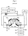
- the apparatus comprises: means 51 for holding powder; irradiation means 52a, 52b, 52c for irradiating the powder with terahertz electromagnetic waves; receiving means 53a, 53b, 53c for receiving the terahertz electromagnetic waves which have passed through the powder to convert the waves into electric signals; means 54 for acquiring from outputs of the receiving means a difference of propagation times or amplitudes between positions of the powder where the terahertz electromagnetic waves pass; and image processing means 55 for processing an image to display the characteristics of the powder in a display based on the difference.
- the apparatus measures the characteristics of the powder.
- a transmittance, a refractive index, a filling ratio and the like of the powder are measured by this means.
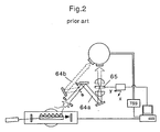
- terahertz waves 64a, 64b on two different wavelengths are generated in a frequency range of about 0.5 to 3 THz, a material 65 to be inspected is irradiated with the terahertz waves on two wavelengths 64a, 64b to measure the transmittances, and presence of a target having dependence of the wavelength on absorption of the terahertz wave is detected from a difference between the transmittances.
- the dependence of DNA of salmon or the like on the wavelength is measured by this means.
- the cuvette is illuminated by an expanded laser beam and imaged on a video Camera by means of a central dark field arrangement comprising two confocal lenses.
- an object of the present invention is to provide a scattered material detection apparatus and method capable of detecting a scattered material such as powder or foam contained in an envelope, a capsule, a container or the like in a non-destructive manner without unsealing the envelope or the like by use of a terahertz wave.
- the terahertz wave has a high transmitting property through the envelope, a plastic container or the like, and usually rectilinearly passes therethrough as such.
- the terahertz wave is usually intensely scattered because of its short wavelength. Therefore, when a rectilinear wave and a scattered wave of terahertz light are measured separately from each other, it is possible to detect the presence of the scattered material such as the powder or the foam in the envelope or the plastic container.
- the present invention is based on such inventive finding.
- the confocal optical system comprises: first and second off-axis parabolic mirrors which face each other; and a shielding member which is positioned between the two off-axis parabolic mirrors and which cuts the rectilinear wave of the terahertz wave and which transmits the scattered wave.
- the first off-axis parabolic mirror has an incidence-side focus and a reflection-side focus along an axial line of the terahertz wave
- the object to be inspected is positioned in the incidence-side focus of the first off-axis parabolic mirror or its vicinity
- the shielding member is positioned in the reflection-side focus of the first off-axis parabolic mirror or its vicinity.
- the confocal optical system comprises: first and second convex lenses which face each other; and a shielding member which is positioned between two convex lenses and which cuts the rectilinear wave of the terahertz wave and which transmits the scattered wave.
- the first convex lens has an incidence-side focus and an outlet-side focus along an axial line of the terahertz wave
- the object to be inspected is positioned in the incidence-side focus of the first convex lens or its vicinity
- the shielding member is positioned in the outlet-side focus of the first convex lens or its vicinity.
- the apparatus and the method of the present invention superior effects are produced.
- the rectilinear wave of the terahertz wave which has passed through the object to be inspected can be cut, and the intensity of the scattered wave can be detected. Therefore, a scattered material such as powder or foam contained in an envelope, a capsule, a container or the like can be detected in a non-destructive manner without unsealing the envelope or the like.
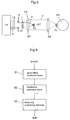
- FIG. 3 is a configuration diagram of a first embodiment of a scattered material detection apparatus of the present invention.
- a scattered material detection apparatus 10 of the present invention is provided with a terahertz wave generation device 12, a terahertz wave irradiation device 14, and a scattering intensity detection device 20.
- the terahertz wave generation device 12 generates a terahertz wave 2.
- the terahertz wave 2 has a constant wavelength in a range of 1 millimeter to 30 micron meter, and is preferably a continuous or pulse wave having a certain output.
- a generation source of the generated terahertz wave may be a spot light source, a linear light source, or a parallel light source.
- the terahertz wave irradiation device 14 irradiates an object 1 to be inspected with the terahertz wave 2.
- the terahertz wave irradiation device 14 comprises: a lens 15 which converts the generated terahertz wave 2 into parallel light; and an iris diaphragm 16 which limits a sectional shape of the parallel light to be smaller than that of the object 1 to be inspected to irradiate the object with the light.
- the generation source of the terahertz wave 2 is the linear light source which is parallel to a drawing sheet surface, and the lens 15 is a cylindrical lens which extends in parallel with the sheet surface.
- the generation source of the terahertz wave 2 is positioned in a linear focal position of the cylindrical lens 15, and the wave is converted into the parallel light whose sectional shape is rectangular by means of the cylindrical lens 15.
- the iris diaphragm 16 has a rectangular aperture which is smaller than the object 1 to be inspected, the output of the terahertz wave 2 with which the object 1 to be inspected is irradiated is kept to be constant, and the object 1 to be inspected is irradiated with a total quantity of output.
- the lens 15 is not limited to this constitution, and a usual convex lens system may be used with respect to the spot light source.
- the iris diaphragm 16 is not limited to this constitution, and may be a circular or rectangular variable diaphragm.
- the scattering intensity detection device 20 cuts a rectilinear wave 3 of the terahertz wave 2 which has passed through the object 1 to be inspected to detect an intensity of a scattered wave 4.
- the scattering intensity detection device 20 comprises: a confocal optical system 22 for interrupting the terahertz wave 2 which has rectilinearly passed through the object 1 to be inspected midway and for condensing the terahertz wave 2 scattered by the object 1 to be inspected in a predetermined position; and a scattering intensity detection unit 28 which detects the intensity of the terahertz wave in the focal position.
- FIG. 4 is an explanatory view of the confocal optical system of FIG. 3 .
- the confocal optical system 22 comprises: first and second off-axis parabolic mirrors 23, 24 which face each other; and a shielding member 27 which is positioned between the two off-axis parabolic mirrors and which cuts the rectilinear wave 3 of the terahertz wave and which transmits the scattered wave 4.
- Each of the first and second off-axis parabolic mirrors 23, 24 is a concave reflective mirror having a parabolic reflective surface as viewed on the drawing sheet.
- the focal positions may be the same or different.
- the first off-axis parabolic mirror 23 has an incidence-side focus F1 and a reflection-side focus F2 along an axial line of the terahertz wave 2.
- the object 1 to be inspected is positioned in the incidence-side focus F1 of the first off-axis parabolic mirror 23 or its vicinity.
- the shielding member 27 is positioned in the reflection-side focus F2 of the first off-axis parabolic mirror 23 or its vicinity.
- the rectilinear wave 3 which has passed through the object 1 to be inspected as such is reflected by the first off-axis parabolic mirror 23, concentrated on the reflection-side focus F2, and cut by the shielding member 27.
- the shielding member 27 is preferably sufficiently small, and has a small reflectance of the terahertz wave 2 as long as this function is satisfied.
- the scattered wave 4 scattered by the object 1 to be inspected is reflected by the first and second off-axis parabolic mirrors 23, 24, and concentrated on the reflection-side focus F3 of the second off-axis parabolic mirror 24.
- the scattering intensity detection unit 28 is, for example, a silicon bolometer, and detects the intensity of the terahertz wave 2 concentrated on the reflection-side focus F3 of the second off-axis parabolic mirror 24.
- the rectilinear wave 3 can be cut, and the intensity of the scattered wave 4 can be detected.
- FIG. 5 is a configuration diagram of a second embodiment of the scattered material detection apparatus of the present invention.
- a confocal optical system 22 comprises: first and second convex lenses 25, 26 which face each other; and a shielding member 27 which is positioned between two convex lenses and which cuts a rectilinear wave 3 of a terahertz wave 2 and which transmits a scattered wave 4.
- Each of the first and second convex lenses 25, 26 may be a single or composite lens.
- the lens may be a circular lens focusing on one point or a linearly focusing cylindrical lens. Focal distances of the lenses may be equal or different.
- the first convex lens 25 has an incidence-side focus F1 and an outlet-side focus F2 along an axial line of the terahertz wave 2.
- the object 1 to be inspected is positioned in the incidence-side focus F1 of the first convex lens 25 or its vicinity, and the shielding member 27 is positioned in the outlet-side focus F2 of the first convex lens 25 or its vicinity.
- the parallel light 2 with which an object 1 to be inspected is irradiated may be rectangular or circular. Another constitution is similar to that of FIG. 4 .
- the rectilinear wave 3 which has passed through the object 1 to be inspected as such is concentrated on the outlet-side focus F2 of the first convex lens 25, and cut by the shielding member 27.
- the scattered wave 4 scattered by the object 1 to be inspected is concentrated on the outlet-side focus F3 of the second convex lens 26. Therefore, according to this constitution, the rectilinear wave 3 can be cut, and the intensity of the scattered wave 4 can be detected.
- FIG. 6 is a flowchart of a scattered material detection method of the present invention. The method of the present invention is performed in the following steps by use of the apparatus described above with reference to FIGS. 3 to 5 .
- a terahertz wave 2 is generated.
- a terahertz wave irradiating step S2 an object 1 to be inspected is irradiated with the generated terahertz wave 2.
- a rectilinear wave 3 of the terahertz wave 2 which has passed through the object 1 to be inspected is cut, and an intensity of a scattered wave 4 is detected.
- the terahertz wave 2 generated in the terahertz wave generating step S1 is converted into parallel light, next a sectional shape of the parallel light is limited to be smaller than that of the object 1 to be inspected, and the object may be irradiated with the light.
- the terahertz wave 2 which has rectilinearly passed through the object 1 to be inspected is interrupted midway, the terahertz wave 2 scattered by the object 1 to be inspected is concentrated in a predetermined position, and the intensity of the terahertz wave in the focal position may be detected.
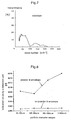
- FIG. 7 shows an example in which a transmittance of an electromagnetic wave with respect to an empty envelope is measured.
- the abscissa indicates the wave number
- the ordinate indicates the transmittance.
- the used envelope is commercially available for airmailing. It is to be noted that the wave number [cm -1 ] is an inverse number of a wavelength.
- a terahertz wave is preferably used as an electromagnetic wave for use in irradiating the object to be inspected whose wave number is preferably in a range of 30 to 70, that is, the wavelength is in a range of 0.1 to 0.3 mm.
- a terahertz wave generation device 12 for generating a terahertz wave 2 of 1.5 THz was used.
- a wavelength was about 0.2 mm.
- concave reflective mirrors were used whose focal distances were 50.8 mm and 76.4 mm, respectively.
- powder of sugar (fructose) was used in consideration of a pre-stage inspection of an inspection of presence of prohibited chemicals in the envelope.
- the powder having particle diameters of 1 mm to 30 micron meter was prepared, divided into four types of particle diameter ranges, and tested.
- FIG. 8 shows obtained measurement results of scattering intensities.
- the abscissa indicates four types of particle diameter ranges in order from the largest particle, and the ordinate indicates values indicated by a detection unit (scattering intensity detection unit 28).
- the powder in the envelope can be identified using this apparatus. It is to be noted that the present invention is not limited to the powder, and is applicable to judgment of presence of such non-uniform materials as to cause scattering, such as medical chemical products contained in capsules or containers.
Landscapes
- Physics & Mathematics (AREA)
- Health & Medical Sciences (AREA)
- Life Sciences & Earth Sciences (AREA)
- General Physics & Mathematics (AREA)
- Spectroscopy & Molecular Physics (AREA)
- Chemical & Material Sciences (AREA)
- Toxicology (AREA)
- Geophysics (AREA)
- General Life Sciences & Earth Sciences (AREA)
- Analytical Chemistry (AREA)
- Biochemistry (AREA)
- General Health & Medical Sciences (AREA)
- Immunology (AREA)
- Pathology (AREA)
- Investigating Or Analysing Materials By Optical Means (AREA)
- Investigating Materials By The Use Of Optical Means Adapted For Particular Applications (AREA)
Claims (5)
- Streumaterial-Erfassungsvorrichtung zum Erfassen von gestreutem Material in einer Hülle, einer Kapsel oder einem Behälter unter Verwendung einer Terahertzwelle mit einer Wellenlänge zwischen 1 mm und 30 µm, umfassend:eine Terahertzwellen-Erzeugungseinrichtung (12), die die Terahertzwelle erzeugt,eine Terahertzwellen-Bestrahlungseinrichtung (14), die ein zu prüfendes Objekt (1) mit der Terahertzwelle bestrahlt, undeine Streuintensitäts-Erfassungseinrichtung (20) zum Schneiden (27) einer geradlinigen Welle (3) der durch das zu prüfende Objekt hindurchgegangenen Terahertzwelle und zum Erfassen (28) der Intensität einer gestreuten Welle (4), wobei:die Streuintensitäts-Erfassungseinrichtung (20) umfasst: ein konfokales optisches System (22) zum Unterbrechen (27) der geradlinig durch das zu prüfende Objekt hindurchgegangenen Terahertzwelle in der Mitte und zum Fokussieren der durch das zu prüfende Objekt gestreuten Terahertzwelle (4) an einer vorbestimmten Position; und eine Streuintensitäts-Erfassungseinheit (28), die die Intensität der Terahertzwelle an der Fokusposition erfasst, unddie Terahertzwellen-Bestrahlungseinrichtung (14) umfasst: eine Linse (15), die die erzeugte Terahertzwelle zu parallelem Licht wandelt; und eine Irismembrane (16), die eine Schnittform des parallelen Lichts begrenzt, sodass diese kleiner als diejenige des zu prüfenden Objekts ist, um das Objekt mit dem Licht zu bestrahlen.
- Streumaterial-Erfassungsvorrichtung nach Anspruch 1, wobei das konfokale optische System (22) umfasst: erste und zweite Off-Axis-Parabolspiegel (23, 24), die einander zugewandt sind; und ein Abschirmungsglied (27), das zwischen den zwei Off-Axis-Parabolspiegeln (23, 24) angeordnet ist und die geradlinige Welle der Terahertzwelle schneidet und die gestreute Welle durchlässt, wobei:der erste Off-Axis-Parabolspiegel (23) einen einfallsseitigen Fokus und einen reflexionsseitigen Fokus entlang einer Axiallinie der Terahertzwelle aufweist,das zu prüfende Objekt (1) an dem einfallsseitigen Fokus des ersten Off-Axis-Parabolspiegels (23) oder in Nachbarschaft dazu positioniert wird, unddas Abschirmungsglied (27) an dem reflexionsseitigen Fokus des ersten Off-Axis-Parabolspiegels (23) oder in Nachbarschaft dazu positioniert wird.
- Streumaterial-Erfassungsvorrichtung nach Anspruch 1, wobei das konfokale optische System umfasst: erste und zweite Konvexlinsen, die einander zugewandt sind; und ein Abschirmungsglied, das zwischen den zwei Konvexlinsen angeordnet ist und die geradlinige Welle der Terahertzwelle schneidet und die gestreute Welle durchlässt, wobei:die erste Konvexlinse einen einfallsseitigen Fokus und einen auslassseitigen Fokus entlang einer Axiallinie der Terahertzwelle aufweist,das zu prüfende Objekt an dem einfallsseitigen Fokus der ersten Konvexlinse oder in Nachbarschaft dazu positioniert wird, unddas Abschirmungsglied an dem auslassseitigen Fokus der ersten Konvexlinse oder in Nachbarschaft dazu positioniert wird.
- Streumaterial-Erfassungsvorrichtung nach einem der Ansprüche 1 bis 3, wobei die Terahertzwellen-Erzeugungseinrichtung (12) eine Linearlichtquelle umfasst und die Linse (15) eine zylindrische Linse ist.
- Streumaterial-Erfassungsverfahren, das eine Terahertzwelle mit einer Wellenlänge zwischen 1 mm und 30 µm verwendet, um gestreutes Material in einer Hülle, einer Kapsel oder einem Behälter zu erfassen, umfassend:einen Terahertzwellen-Erzeugungsschritt zum Erzeugen einer Terahertzwelle,einen Terahertzwellen-Bestrahlungsschritt zum Bestrahlen eines zu prüfenden Objekts (1) mit der Terahertzwelle, undeinen Streuintensitäts-Erfassungsschritt zum Schneiden (27) einer geradlinigen Welle der durch das zu prüfende Objekt hindurchgegangenen Terahertzwelle und zum Erfassen (28) der Intensität einer gestreuten Welle, wobei:in dem Terahertzwellen-Bestrahlungsschritt die in dem Terahertzwellen-Erzeugungsschritt erzeugte Terahertzwelle mittels einer Linse (15) zu parallelem Licht gewandelt wird und die Schnittform des parallelen Lichts mittels einer Irismembrane (16) begrenzt wird, sodass sie kleiner als diejenige des zu prüfenden Objekts ist, um das Objekt mit dem Licht zu bestrahlen, undin dem Streuintensitäts-Erfassungsschritt die geradlinig durch das zu prüfende Objekt hindurchgegangene Terahertzwelle (3) durch ein konfokales optisches System (22) in der Mitte unterbrochen wird, die durch das zu prüfende Objekt gestreute Terahertzwelle (4) an einer vorbestimmten Position fokussiert wird und die Intensität der Terahertzwelle an der Fokusposition erfasst wird (28).
Applications Claiming Priority (1)
| Application Number | Priority Date | Filing Date | Title |
|---|---|---|---|
| JP2004254075A JP4480146B2 (ja) | 2004-09-01 | 2004-09-01 | テラヘルツ波を用いた散乱物検出装置と方法 |
Publications (2)
| Publication Number | Publication Date |
|---|---|
| EP1632769A1 EP1632769A1 (de) | 2006-03-08 |
| EP1632769B1 true EP1632769B1 (de) | 2016-07-06 |
Family
ID=35169352
Family Applications (1)
| Application Number | Title | Priority Date | Filing Date |
|---|---|---|---|
| EP05018527.1A Ceased EP1632769B1 (de) | 2004-09-01 | 2005-08-25 | Vorrichtung und Methode zur Detektion streuenden Materials durch Transmission von Terahertzwellen, wobei die geradlinig transmittierte, ungestreute Komponente unterdrückt wird |
Country Status (3)
| Country | Link |
|---|---|
| US (1) | US7291838B2 (de) |
| EP (1) | EP1632769B1 (de) |
| JP (1) | JP4480146B2 (de) |
Families Citing this family (27)
| Publication number | Priority date | Publication date | Assignee | Title |
|---|---|---|---|---|
| US9909986B2 (en) | 2003-10-15 | 2018-03-06 | Applied Research And Photonics, Inc. | Thickness determination and layer characterization using terahertz scanning reflectometry |
| US8620132B2 (en) * | 2006-09-27 | 2013-12-31 | Anis Rahman | Terahertz scanning reflectometer |
| US7781737B2 (en) * | 2006-12-20 | 2010-08-24 | Schlumberger Technology Corporation | Apparatus and methods for oil-water-gas analysis using terahertz radiation |
| JP2008185552A (ja) * | 2007-01-31 | 2008-08-14 | Tohoku Univ | 測定装置および測定方法 |
| JP5717335B2 (ja) * | 2009-01-23 | 2015-05-13 | キヤノン株式会社 | 分析装置 |
| JP5240858B2 (ja) * | 2009-09-03 | 2013-07-17 | 独立行政法人理化学研究所 | 単色波長可変型テラヘルツ波発生/検出システム及び方法 |
| JP2011153856A (ja) * | 2010-01-26 | 2011-08-11 | Toshiba Corp | テラヘルツ波を用いた粒径測定装置及び粒径測定方法 |
| CN102221525B (zh) | 2010-04-14 | 2015-04-15 | 深圳迈瑞生物医疗电子股份有限公司 | 一种样本检测光学系统、样本分析装置 |
| US9164042B2 (en) | 2011-02-10 | 2015-10-20 | Hitachi High-Technologies Corporation | Device for detecting foreign matter and method for detecting foreign matter |
| JP2012185151A (ja) * | 2011-02-17 | 2012-09-27 | Arkray Inc | テラヘルツ波の特性測定方法、物質検出方法、測定用具、テラヘルツ波の特性測定装置、及び物質検出装置 |
| DE102011112697B4 (de) * | 2011-08-31 | 2013-03-14 | Fraunhofer-Gesellschaft zur Förderung der angewandten Forschung e.V. | Verfahren und Vorrichtung zum Bestimmen einer Substanz unter Verwendung von THz-Strahlung |
| JP5994416B2 (ja) * | 2012-06-18 | 2016-09-21 | ニプロ株式会社 | テラヘルツパルス波を用いた粉末中の異物検出装置および異物検出方法 |
| CN103792520B (zh) * | 2013-01-30 | 2017-05-17 | 承德石油高等专科学校 | 太赫兹目标散射特性测试装置及测试方法 |
| US9606054B2 (en) | 2013-09-30 | 2017-03-28 | Advantest Corporation | Methods, sampling device and apparatus for terahertz imaging and spectroscopy of coated beads, particles and/or microparticles |
| EP2892031B1 (de) * | 2014-01-06 | 2019-07-24 | Neopost Technologies | Hybrides sicheres Schließfachsystem zum Versenden, Hinterlegen und Abholen von Postsendungen |
| EP2891433B1 (de) * | 2014-01-06 | 2018-11-21 | Neopost Technologies | Sichere Schließfachsystem zum Hinterlegen und Abholen von Postsendungen |
| EP2902352B1 (de) | 2014-01-31 | 2016-12-21 | Neopost Technologies | Tragbarer griffspender |
| US9417181B2 (en) | 2014-05-08 | 2016-08-16 | Advantest Corporation | Dynamic measurement of density using terahertz radiation with real-time thickness measurement for process control |
| CN107532883B (zh) * | 2015-03-03 | 2020-08-14 | 斯考拉股份公司 | 用于测量条状体的直径和/或壁厚的设备和方法 |
| EP3325388B1 (de) | 2015-07-20 | 2019-12-11 | Neopost Technologies | Verbesserter tragbarer griffspender |
| EP3190540B1 (de) | 2016-01-06 | 2019-05-22 | Neopost Technologies | Uhf-rfid-vorrichtung zur kommunikation mit uhf-rfid-etiketten in einem kleinen hohlraum |
| US10648864B2 (en) | 2016-11-01 | 2020-05-12 | Korea Food Research Institute | High-resolution terahertz wave concentration module, scattered light detection module, and high-resolution inspection apparatus using terahertz bessel beam |
| CN113466171A (zh) * | 2016-11-01 | 2021-10-01 | 韩国食品研究院 | 利用贝塞尔光束的高分辨率检查装置 |
| US11042833B2 (en) | 2017-01-06 | 2021-06-22 | Quadient Technologies France | Automated autovalidating locker system |
| CN113126174B (zh) * | 2019-12-30 | 2022-10-04 | 清华大学 | 被动式安检设备及其光学装置 |
| GB202001397D0 (en) * | 2020-01-31 | 2020-03-18 | Odx Innovations Ltd | Apparatus, system and method for measuring properties of a sample |
| CN113625458B (zh) * | 2021-09-13 | 2022-04-22 | 北京理工大学 | 双共焦反射式变倍扩束镜 |
Family Cites Families (10)
| Publication number | Priority date | Publication date | Assignee | Title |
|---|---|---|---|---|
| US4121247A (en) * | 1977-04-21 | 1978-10-17 | Eastman Kodak Company | Population and profile display of transparent bodies in a transparent mass |
| US6153873A (en) * | 1998-05-20 | 2000-11-28 | E. I. Dupont De Numours And Company | Optical probe having an imaging apparatus |
| JP2002072269A (ja) * | 2000-08-30 | 2002-03-12 | Inst Of Physical & Chemical Res | テラヘルツ波発生方法及び装置 |
| EP1248092B1 (de) * | 2001-03-09 | 2010-09-15 | Novartis AG | Linsenprüfung |
| JP3747319B2 (ja) * | 2002-04-09 | 2006-02-22 | 独立行政法人理化学研究所 | テラヘルツ波発生装置とその同調方法 |
| US6977379B2 (en) * | 2002-05-10 | 2005-12-20 | Rensselaer Polytechnic Institute | T-ray Microscope |
| JP2004061455A (ja) | 2002-07-31 | 2004-02-26 | Communication Research Laboratory | テラヘルツ電磁波による粉体物性測定装置および方法 |
| JP2004108905A (ja) | 2002-09-18 | 2004-04-08 | Inst Of Physical & Chemical Res | テラヘルツ波を用いた差分イメージング方法及び装置 |
| US7129491B2 (en) * | 2002-11-13 | 2006-10-31 | Rensselaer Polytechnic Institute | Diffraction mode terahertz tomography |
| JP2005114413A (ja) * | 2003-10-03 | 2005-04-28 | Si Seiko Co Ltd | 物質検出方法とその装置 |
-
2004
- 2004-09-01 JP JP2004254075A patent/JP4480146B2/ja not_active Expired - Fee Related
-
2005
- 2005-08-25 EP EP05018527.1A patent/EP1632769B1/de not_active Ceased
- 2005-09-01 US US11/216,153 patent/US7291838B2/en not_active Expired - Lifetime
Non-Patent Citations (7)
| Title |
|---|
| "Advanced Light Microscopy", 1 January 1988, WARSZAWA, ISBN: 978-0-44-498940-6, article MAKSYMILIAN PLUTA: "Central dark-field microscopy", pages: 110, XP055175813 * |
| "Handbook of Biological Confocal Microscopy", 1 January 1995, NEW YORK, article ERNST H K STELZER: "The Intermediate Optical System of Laser-Scanning Confocal Microscopes", pages: 139 - 140, XP055175817 * |
| "Medical applications of lasers", 1 January 2002, KLUWER ACADEMIC PUBLISHER, ISBN: 97807923766210, article "SPATIAL SPECKLE CORRELOMETRY", pages: 181 - 182, XP055175818 * |
| KALINUSHKIN V P ET AL: "Elastic mid-infrared light scattering: A basis for microscopy of large-scale electrically active defects in semiconducting materials", REVIEW OF SCIENTIFIC INSTRUMENTS, AIP, MELVILLE, NY, US, vol. 70, no. 11, 1 November 1999 (1999-11-01), pages 4331 - 4343, XP012037189, ISSN: 0034-6748, DOI: 10.1063/1.1150076 * |
| MCCAY M H ET AL: "The measurement of transient dendrite tip interface supersaturation in NH4Cl-H2O using optical techniques", JOURNAL OF CRYSTAL GROWTH, ELSEVIER, AMSTERDAM, NL, vol. 126, no. 2-3, 2 January 1993 (1993-01-02), pages 223 - 228, XP024438198, ISSN: 0022-0248, [retrieved on 19930102], DOI: 10.1016/0022-0248(93)90029-V * |
| TOOMAS KÜBARSEPP: "Nonlinearity measurements of silicon photodetectors", APPLIED OPTICS, OPTICAL SOCIETY OF AMERICA, WASHINGTON, DC; US, vol. 37, no. 13, 1 May 1998 (1998-05-01), pages 2716 - 2722, XP002362533, ISSN: 0003-6935, DOI: 10.1364/AO.37.002716 * |
| Z LACZIK ET AL: "SCANNING INFRA-RED MICROSCOPY OF SEMICONDUCTING MATERIALS: REVIEW OF THEORY AND APPLICATIONS", ALTECH 95 - ANALYTICAL TECHNIQUES FOR SEMICONDUCTOR MATERIALS AND PROCESS CHARACTERIZATION II, 1 January 1995 (1995-01-01), XP055175814, ISBN: 978-1-56-677122-1 * |
Also Published As
| Publication number | Publication date |
|---|---|
| US20060043298A1 (en) | 2006-03-02 |
| JP2006071412A (ja) | 2006-03-16 |
| US7291838B2 (en) | 2007-11-06 |
| EP1632769A1 (de) | 2006-03-08 |
| JP4480146B2 (ja) | 2010-06-16 |
Similar Documents
| Publication | Publication Date | Title |
|---|---|---|
| EP1632769B1 (de) | Vorrichtung und Methode zur Detektion streuenden Materials durch Transmission von Terahertzwellen, wobei die geradlinig transmittierte, ungestreute Komponente unterdrückt wird | |
| Ingal et al. | X-ray plane-wave topography observation of the phase contrast from a non-crystalline object | |
| CN101663575B (zh) | 使用太赫辐射的成像方法和装置 | |
| US6957099B1 (en) | Method and apparatus for terahertz imaging | |
| US7230708B2 (en) | Method and device for photothermal examination of microinhomogeneities | |
| CN105388140B (zh) | 现场隐形指纹显示及其内含物质测量仪 | |
| EP2299898B1 (de) | Vorrichtung zur beschaffung biologischer informationen | |
| KR101392311B1 (ko) | 테라파 베셀 빔을 이용한 물체 검사 장치 | |
| KR101702380B1 (ko) | THz 빔 스캔을 이용한 고속 3차원 영상 탐지 장치 | |
| EP2863211B1 (de) | Vorrichtung zur erkennung von verunreinigungen in einem pulver unter verwendung von terahertz-impulswellen sowie verfahren zur erkennung von verunreinigungen | |
| US7381955B2 (en) | Method and apparatus for inspecting target by tera-hertz wave spectrometry | |
| KR19980703516A (ko) | 하드 x-선을 사용한 위상차 화상용 단순화 조건 및 구성 | |
| AU5094300A (en) | Three dimensional imaging | |
| CN101536016A (zh) | 光学微层析成像的焦平面跟踪 | |
| CN101990633A (zh) | 用于近临界反射光谱学的方法、装置和套件 | |
| US20140066743A1 (en) | Object information acquiring apparatus | |
| KR101691544B1 (ko) | 비축대칭 렌즈를 포함하는 THz 빔 스캔 고속 3차원 영상 탐지 장치 | |
| CN106769997A (zh) | 一种太赫兹扫描成像装置 | |
| GB2347835A (en) | Terahertz radiation imaging | |
| Morita et al. | Terahertz technique for detection of microleaks in the seal of flexible plastic packages | |
| US20150241348A1 (en) | Information acquiring apparatus and information acquiring method | |
| JP2009075134A (ja) | 細菌又は毒性物質の同定装置 | |
| CN113504203A (zh) | 高分辨率太赫兹波聚光模块 | |
| Gerasimov et al. | Obtaining spectrally selective images of objects in attenuated total reflection regime in real time in visible and terahertz ranges | |
| Meesen et al. | Use of a CSLM for the analysis of chemical etched tracks in PADC |
Legal Events
| Date | Code | Title | Description |
|---|---|---|---|
| PUAI | Public reference made under article 153(3) epc to a published international application that has entered the european phase |
Free format text: ORIGINAL CODE: 0009012 |
|
| 17P | Request for examination filed |
Effective date: 20051228 |
|
| AK | Designated contracting states |
Kind code of ref document: A1 Designated state(s): AT BE BG CH CY CZ DE DK EE ES FI FR GB GR HU IE IS IT LI LT LU LV MC NL PL PT RO SE SI SK TR |
|
| AX | Request for extension of the european patent |
Extension state: AL BA HR MK YU |
|
| AKX | Designation fees paid |
Designated state(s): DE FR GB |
|
| RAP1 | Party data changed (applicant data changed or rights of an application transferred) |
Owner name: RIKEN Owner name: SHIBUYA SEIKI CO., LTD. |
|
| REG | Reference to a national code |
Ref country code: DE Ref legal event code: R079 Ref document number: 602005049665 Country of ref document: DE Free format text: PREVIOUS MAIN CLASS: G01N0021350000 Ipc: G01N0021356300 |
|
| RIC1 | Information provided on ipc code assigned before grant |
Ipc: G01N 21/3563 20140101AFI20151210BHEP Ipc: G01N 21/3581 20140101ALI20151210BHEP Ipc: G01V 8/00 20060101ALI20151210BHEP |
|
| GRAP | Despatch of communication of intention to grant a patent |
Free format text: ORIGINAL CODE: EPIDOSNIGR1 |
|
| INTG | Intention to grant announced |
Effective date: 20160122 |
|
| GRAS | Grant fee paid |
Free format text: ORIGINAL CODE: EPIDOSNIGR3 |
|
| GRAA | (expected) grant |
Free format text: ORIGINAL CODE: 0009210 |
|
| AK | Designated contracting states |
Kind code of ref document: B1 Designated state(s): DE FR GB |
|
| REG | Reference to a national code |
Ref country code: GB Ref legal event code: FG4D |
|
| REG | Reference to a national code |
Ref country code: DE Ref legal event code: R096 Ref document number: 602005049665 Country of ref document: DE |
|
| REG | Reference to a national code |
Ref country code: FR Ref legal event code: PLFP Year of fee payment: 12 |
|
| REG | Reference to a national code |
Ref country code: DE Ref legal event code: R097 Ref document number: 602005049665 Country of ref document: DE |
|
| PLBE | No opposition filed within time limit |
Free format text: ORIGINAL CODE: 0009261 |
|
| STAA | Information on the status of an ep patent application or granted ep patent |
Free format text: STATUS: NO OPPOSITION FILED WITHIN TIME LIMIT |
|
| 26N | No opposition filed |
Effective date: 20170407 |
|
| REG | Reference to a national code |
Ref country code: FR Ref legal event code: PLFP Year of fee payment: 13 |
|
| REG | Reference to a national code |
Ref country code: FR Ref legal event code: PLFP Year of fee payment: 14 |
|
| PGFP | Annual fee paid to national office [announced via postgrant information from national office to epo] |
Ref country code: FR Payment date: 20180830 Year of fee payment: 14 |
|
| PGFP | Annual fee paid to national office [announced via postgrant information from national office to epo] |
Ref country code: GB Payment date: 20180830 Year of fee payment: 14 |
|
| PGFP | Annual fee paid to national office [announced via postgrant information from national office to epo] |
Ref country code: DE Payment date: 20190822 Year of fee payment: 15 |
|
| GBPC | Gb: european patent ceased through non-payment of renewal fee |
Effective date: 20190825 |
|
| PG25 | Lapsed in a contracting state [announced via postgrant information from national office to epo] |
Ref country code: FR Free format text: LAPSE BECAUSE OF NON-PAYMENT OF DUE FEES Effective date: 20190831 |
|
| PG25 | Lapsed in a contracting state [announced via postgrant information from national office to epo] |
Ref country code: GB Free format text: LAPSE BECAUSE OF NON-PAYMENT OF DUE FEES Effective date: 20190825 |
|
| REG | Reference to a national code |
Ref country code: DE Ref legal event code: R119 Ref document number: 602005049665 Country of ref document: DE |
|
| PG25 | Lapsed in a contracting state [announced via postgrant information from national office to epo] |
Ref country code: DE Free format text: LAPSE BECAUSE OF NON-PAYMENT OF DUE FEES Effective date: 20210302 |