EP1632689A2 - Procédé pour la commande d'un embrayage, en particulier pour transmission à changement parallèle avec embrayage humide ou embrayage humide double - Google Patents
Procédé pour la commande d'un embrayage, en particulier pour transmission à changement parallèle avec embrayage humide ou embrayage humide double Download PDFInfo
- Publication number
- EP1632689A2 EP1632689A2 EP05018122A EP05018122A EP1632689A2 EP 1632689 A2 EP1632689 A2 EP 1632689A2 EP 05018122 A EP05018122 A EP 05018122A EP 05018122 A EP05018122 A EP 05018122A EP 1632689 A2 EP1632689 A2 EP 1632689A2
- Authority
- EP
- European Patent Office
- Prior art keywords
- clutch
- temperature
- viscosity
- transmission
- control
- Prior art date
- Legal status (The legal status is an assumption and is not a legal conclusion. Google has not performed a legal analysis and makes no representation as to the accuracy of the status listed.)
- Withdrawn
Links
Images
Classifications
-
- F—MECHANICAL ENGINEERING; LIGHTING; HEATING; WEAPONS; BLASTING
- F16—ENGINEERING ELEMENTS AND UNITS; GENERAL MEASURES FOR PRODUCING AND MAINTAINING EFFECTIVE FUNCTIONING OF MACHINES OR INSTALLATIONS; THERMAL INSULATION IN GENERAL
- F16D—COUPLINGS FOR TRANSMITTING ROTATION; CLUTCHES; BRAKES
- F16D48/00—External control of clutches
- F16D48/06—Control by electric or electronic means, e.g. of fluid pressure
- F16D48/062—Control by electric or electronic means, e.g. of fluid pressure of a clutch system with a plurality of fluid actuated clutches
-
- F—MECHANICAL ENGINEERING; LIGHTING; HEATING; WEAPONS; BLASTING
- F16—ENGINEERING ELEMENTS AND UNITS; GENERAL MEASURES FOR PRODUCING AND MAINTAINING EFFECTIVE FUNCTIONING OF MACHINES OR INSTALLATIONS; THERMAL INSULATION IN GENERAL
- F16D—COUPLINGS FOR TRANSMITTING ROTATION; CLUTCHES; BRAKES
- F16D48/00—External control of clutches
- F16D48/06—Control by electric or electronic means, e.g. of fluid pressure
- F16D48/066—Control of fluid pressure, e.g. using an accumulator
-
- F—MECHANICAL ENGINEERING; LIGHTING; HEATING; WEAPONS; BLASTING
- F16—ENGINEERING ELEMENTS AND UNITS; GENERAL MEASURES FOR PRODUCING AND MAINTAINING EFFECTIVE FUNCTIONING OF MACHINES OR INSTALLATIONS; THERMAL INSULATION IN GENERAL
- F16D—COUPLINGS FOR TRANSMITTING ROTATION; CLUTCHES; BRAKES
- F16D2500/00—External control of clutches by electric or electronic means
- F16D2500/10—System to be controlled
- F16D2500/104—Clutch
- F16D2500/10406—Clutch position
- F16D2500/10412—Transmission line of a vehicle
-
- F—MECHANICAL ENGINEERING; LIGHTING; HEATING; WEAPONS; BLASTING
- F16—ENGINEERING ELEMENTS AND UNITS; GENERAL MEASURES FOR PRODUCING AND MAINTAINING EFFECTIVE FUNCTIONING OF MACHINES OR INSTALLATIONS; THERMAL INSULATION IN GENERAL
- F16D—COUPLINGS FOR TRANSMITTING ROTATION; CLUTCHES; BRAKES
- F16D2500/00—External control of clutches by electric or electronic means
- F16D2500/10—System to be controlled
- F16D2500/108—Gear
- F16D2500/1086—Concentric shafts
-
- F—MECHANICAL ENGINEERING; LIGHTING; HEATING; WEAPONS; BLASTING
- F16—ENGINEERING ELEMENTS AND UNITS; GENERAL MEASURES FOR PRODUCING AND MAINTAINING EFFECTIVE FUNCTIONING OF MACHINES OR INSTALLATIONS; THERMAL INSULATION IN GENERAL
- F16D—COUPLINGS FOR TRANSMITTING ROTATION; CLUTCHES; BRAKES
- F16D2500/00—External control of clutches by electric or electronic means
- F16D2500/30—Signal inputs
- F16D2500/304—Signal inputs from the clutch
- F16D2500/30404—Clutch temperature
-
- F—MECHANICAL ENGINEERING; LIGHTING; HEATING; WEAPONS; BLASTING
- F16—ENGINEERING ELEMENTS AND UNITS; GENERAL MEASURES FOR PRODUCING AND MAINTAINING EFFECTIVE FUNCTIONING OF MACHINES OR INSTALLATIONS; THERMAL INSULATION IN GENERAL
- F16D—COUPLINGS FOR TRANSMITTING ROTATION; CLUTCHES; BRAKES
- F16D2500/00—External control of clutches by electric or electronic means
- F16D2500/30—Signal inputs
- F16D2500/304—Signal inputs from the clutch
- F16D2500/30406—Clutch slip
-
- F—MECHANICAL ENGINEERING; LIGHTING; HEATING; WEAPONS; BLASTING
- F16—ENGINEERING ELEMENTS AND UNITS; GENERAL MEASURES FOR PRODUCING AND MAINTAINING EFFECTIVE FUNCTIONING OF MACHINES OR INSTALLATIONS; THERMAL INSULATION IN GENERAL
- F16D—COUPLINGS FOR TRANSMITTING ROTATION; CLUTCHES; BRAKES
- F16D2500/00—External control of clutches by electric or electronic means
- F16D2500/30—Signal inputs
- F16D2500/308—Signal inputs from the transmission
- F16D2500/30802—Transmission oil properties
- F16D2500/30803—Oil temperature
-
- F—MECHANICAL ENGINEERING; LIGHTING; HEATING; WEAPONS; BLASTING
- F16—ENGINEERING ELEMENTS AND UNITS; GENERAL MEASURES FOR PRODUCING AND MAINTAINING EFFECTIVE FUNCTIONING OF MACHINES OR INSTALLATIONS; THERMAL INSULATION IN GENERAL
- F16D—COUPLINGS FOR TRANSMITTING ROTATION; CLUTCHES; BRAKES
- F16D2500/00—External control of clutches by electric or electronic means
- F16D2500/30—Signal inputs
- F16D2500/312—External to the vehicle
- F16D2500/3121—Ambient conditions, e.g. air humidity, air temperature, ambient pressure
- F16D2500/3122—Ambient temperature
-
- F—MECHANICAL ENGINEERING; LIGHTING; HEATING; WEAPONS; BLASTING
- F16—ENGINEERING ELEMENTS AND UNITS; GENERAL MEASURES FOR PRODUCING AND MAINTAINING EFFECTIVE FUNCTIONING OF MACHINES OR INSTALLATIONS; THERMAL INSULATION IN GENERAL
- F16D—COUPLINGS FOR TRANSMITTING ROTATION; CLUTCHES; BRAKES
- F16D2500/00—External control of clutches by electric or electronic means
- F16D2500/70—Details about the implementation of the control system
- F16D2500/704—Output parameters from the control unit; Target parameters to be controlled
- F16D2500/70422—Clutch parameters
- F16D2500/70426—Clutch slip
Definitions
- the invention relates to a method for the clutch control of wet clutches, in particular wet double clutches for e.g. Parallel shift.
- gear oil is present in wet clutches or wet double clutches in the clutch bell acts on transmissions with such clutches an additional drag torque on the transmission input shafts.
- the drag torque depends on the viscosity of the gearbox oil. Particularly at low temperatures of the transmission oils commonly used, for example in so-called ATF oils, the viscosity of the transmission oil and thus the drag torque increases sharply.
- a method for compensating increased toughness of a hydraulic fluid for operating an automated clutch is known.
- a characteristic temperature is determined, such as an outside air temperature, cooling water temperature, intake air temperature, or another temperature that is either measured directly or determined from other quantities using a mathematical model becomes.
- the relatively tough hydraulic fluid may not flow through a line between the master cylinder and slave cylinder quickly enough, so that builds up a negative pressure in the working chamber of the master cylinder. If the piston in the master cylinder does not pass over a sniffer bore during its movement, a change in the system volume occurs, under which the actuating accuracy of the coupling suffers.
- the movement speed of the master piston in the closing direction of the clutch is changed to slower speeds at low temperatures.
- the slower speed is sufficient for the hydraulic fluid to be able to flow through the line between the master cylinder and the slave cylinder, so that no negative pressure builds up in the working space of the master cylinder.
- DE 198 23 772 A1 proposes to run over the sniffer bore of the master cylinder at low temperatures always when closing the clutch, so that defined initial conditions prevail at the next actuation cycle.
- EP 0 479 464 B1 discloses a method for determining the viscosity of the transmission oil, in which, instead of introducing a separate temperature probe for measuring a characteristic temperature, the transmission sump lubricant viscosity is detected from a deceleration of the input shaft speed when the transmission is idling and the clutch is disengaged. From the known lubricant characteristics and the deceleration rate of the shaft, the sump temperature or a state "cold / not cold" is determined.
- the invention has for its object to further develop a clutch control of wet clutches such that the period in which a deviating from the normal clutch control clutch control is made or in which a perceptible change in the switching time of the transmission is present, kept short.
- the threshold is chosen to be equivalent to a viscosity that an average driver does not yet is perceived as a slower shift.
- a clutch control is performed such that additional clutch energy is transferred in the form of heat to the clutch fluid, so that the heating is accelerated.
- the temperature of the clutch fluid is checked at least periodically. Once the temperature has exceeded the threshold or after a timeout with modified clutch control, after exceeding the threshold temperature can be expected, the clutch control is resumed in normal operation.
- the invention is based on the idea of keeping the time in which the transmission oil viscosity is significantly different from the normal state as short as possible. It is exploited that energy is transmitted in the form of heat to the transmission oil through the clutch and the transmission during operation.
- the invention takes advantage of this fact by taking targeted, additional measures when it is found that there is a significantly increased viscosity of the transmission oil which leads to a more rapid increase in the temperature of the transmission oil than usual.
- normal operation With the terms “normal operation”, “normal state” and “normal control” u.ä. is each referred to the operation at normal temperatures in which the transmission oil viscosity is not significantly increased.
- the actual temperature ranges for such "normal operation” depend on the gear oil used and its temperature behavior. In currently used transmission oils are areas in which a clutch control according to the invention is used, temperatures below -10 ° C, since in this temperature range, the transmission oil has a much higher viscosity at longer downtime.
- the temperature increase of the transmission oil takes place to a significant extent by transmission of clutch energy to the transmission oil by the clutch control is changed from the normal operation.
- the energy transferred to the transmission or engine oil by the transmission or engine contributes, as usual, to normal heating but not to accelerated heating at low temperatures.
- Coupling energy is such an energy that is released by targeted influence of the coupling in the form of heat, eg clutch friction, slip, etc.
- the viscosity of the transmission oil is determined based on a temperature, preferably the ambient temperature or the temperature of the transmission oil.
- the temperature is measured by a temperature sensor.
- it can also be determined using a mathematical model, as described, for example, in EP 0 479 464 B1.
- the downtime of the vehicle is additionally determined, since even at very low temperatures ( ⁇ -10 ° C) but very short downtime, the transmission oil stores residual heat and thus has no significantly increased viscosity.
- a transmission oil temperature is measured to verify how long the low temperature clutch control operation is to be maintained.
- the most accurate period of time can be determined during which the operation of the clutch control, which is changed compared with normal operation, is used.
- the clutch / transmission control adapted to the low temperatures is switched to normal operation, i.e. that the changed clutch control is maintained for a maximum of a predetermined time.
- the transmission of additional clutch energy to the transmission oil preferably takes place by increasing the starting speed, by prolonged slip phases during starts and shifts, or by switching to a slip control map, which applies specifically to low temperatures and has an increased slip speed. Combinations of the above measures are possible.
- the use of a specially adapted slip control map especially for low temperatures has the advantage that in addition to an increased energy or heat input into the transmission oil better isolation of the engine with regard to vibrations or shocks is possible to compensate for troubled running properties at low temperatures.
- Whether the low-temperature clutch control method is executed can be determined before each startup or every start-up of a motor vehicle. This check can be limited to the winter months by assessing the viscosity of the clutch fluid only when an on-board computer detects "winter", e.g. depending on calendar information, or if the driver has activated a winter mode of the vehicle.
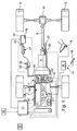
- the attached figure shows a drive train of a motor vehicle with a block diagram of the clutch control device.
- the motor vehicle has an engine, for example an internal combustion engine 2, which is connected via a clutch 4 to a transmission, preferably a parallel shift transmission 6.
- the transmission drives via a cardan shaft 8 and a differential 10, the rear wheels 12 of the vehicle.
- a brake system 14 is provided with a brake device 16 which is actuated via a brake pedal 18.
- the clutch 4 is automated and is actuated by an actuator unit, such as an actuator 25, via a master cylinder 27 and slave cylinder 29.
- the clutch is preferably a wet double clutch. Double clutches are used eg for parallel gearboxes. Wet clutches are those clutches which lie in the oil bath and are moved there.
- a wet double clutch 4 two clutch actuators and corresponding clutch actuations of master cylinder / slave cylinder (reference numerals 25, 27, 29) are provided, of which only one element is shown in the drawing.
- the slave cylinder 29 cooperates with a clutch lever 48, which is rotated by a clutch return spring, not shown, in its rest position, in which the clutch 4 is fully closed, ie can transmit maximum torque.
- the actuator 25 is controlled by a control unit, such as a control unit.
- a control unit such as a control unit.
- an electronic control unit 31 driven from which includes a microprocessor and data from, for example, a sensor 32 for the engine speed, a sensor 34 for detecting the wheel speed of the vehicle, a sensor 36 for detecting a shift request by operating the gear lever 23, a sensor 38th for detecting the position of the clutch 4, a sensor 40 for the position of the actuator 25, a sensor 42 for detecting the cooling water temperature, a sensor 44 for detecting the temperature of the intake air receives.
- the device has a detection unit in the form of a temperature sensor 50 for determining a temperature.
- the detected temperature e.g. is also the control unit 31, which drives the clutch 4, supplied.
- the transmission oil temperature can also be detected by a sensor 52, or a transmission oil temperature can be estimated from the speed behavior of the transmission shaft.
- the control unit 31 determines the increased viscosity of the transmission oil on the basis of the temperature detected by the temperature sensor 50 and / or the temperature sensor 52 or an alternative device in conjunction with the standstill time of the vehicle detected by the sensor 54.
- the viscosity of the gear oil could also be detected otherwise, which is however expensive in relation to a temperature measurement and is therefore not preferred.
- the controller 31 determines that there is increased transmission oil viscosity due to low temperatures, it adjusts the clutch control for the clutch 4 to operate at low temperatures.
- an operating state is selected in which the clutch 4 transmits additional coupling energy, for example, loop energy or friction energy resulting from slippage, to the transmission oil.
- additional coupling energy for example, loop energy or friction energy resulting from slippage
- the control unit 31 During the changed operation, ie the clutch control at lower temperatures, the control unit continues to detect the transmission oil temperature by the temperature sensor 52 and switches on reaching a Transmission oil temperature, which corresponds to a tolerable low viscosity, or at a transmission oil temperature that corresponds to the operating temperature to normal operation.
- Suitable measures which the control unit 31 can initiate and monitor during the changed clutch operation are the increase in the starting speed, extended slip phases during starts and shifts and / or the use of a slip control characteristic for the clutch 4, which is set up especially for low temperatures and increased slip speeds having.
- these measures are controlled in combination by the control unit 31.
Landscapes
- Engineering & Computer Science (AREA)
- General Engineering & Computer Science (AREA)
- Physics & Mathematics (AREA)
- Fluid Mechanics (AREA)
- Mechanical Engineering (AREA)
- Control Of Transmission Device (AREA)
- Hydraulic Clutches, Magnetic Clutches, Fluid Clutches, And Fluid Joints (AREA)
Applications Claiming Priority (1)
| Application Number | Priority Date | Filing Date | Title |
|---|---|---|---|
| DE102004042643 | 2004-09-03 |
Publications (2)
| Publication Number | Publication Date |
|---|---|
| EP1632689A2 true EP1632689A2 (fr) | 2006-03-08 |
| EP1632689A3 EP1632689A3 (fr) | 2006-04-12 |
Family
ID=35033602
Family Applications (1)
| Application Number | Title | Priority Date | Filing Date |
|---|---|---|---|
| EP05018122A Withdrawn EP1632689A3 (fr) | 2004-09-03 | 2005-08-20 | Procédé pour la commande d'un embrayage, en particulier pour transmission à changement parallèle avec embrayage humide ou embrayage humide double |
Country Status (2)
| Country | Link |
|---|---|
| US (1) | US7291091B2 (fr) |
| EP (1) | EP1632689A3 (fr) |
Cited By (4)
| Publication number | Priority date | Publication date | Assignee | Title |
|---|---|---|---|---|
| EP2060820A3 (fr) * | 2007-11-15 | 2010-04-07 | LuK Lamellen und Kupplungsbau Beteiligungs KG | Procédé de commande d'un embrayage à frictions automatisé |
| WO2012110656A1 (fr) * | 2011-02-18 | 2012-08-23 | Land Rover | Véhicule et procédé et système permettant de commander un véhicule |
| WO2014068399A1 (fr) * | 2012-10-30 | 2014-05-08 | Toyota Jidosha Kabushiki Kaisha | Dispositif et procédé de commande d'entraînement pour véhicule |
| WO2018046045A1 (fr) * | 2016-09-09 | 2018-03-15 | Schaeffler Technologies AG & Co. KG | Procédé d'adaptation d'une compensation de température d'un système d'embrayage hydraulique |
Families Citing this family (2)
| Publication number | Priority date | Publication date | Assignee | Title |
|---|---|---|---|---|
| JP5176184B2 (ja) * | 2008-03-28 | 2013-04-03 | 本田技研工業株式会社 | クラッチ制御装置 |
| EP3677755A1 (fr) * | 2013-04-12 | 2020-07-08 | Dana Limited | Système et procédé de surveillance et de pronostic pour déterminer une durée de vie utile restante de lubrifiant dans des transmissions d'embrayage à bain d'huile |
Citations (3)
| Publication number | Priority date | Publication date | Assignee | Title |
|---|---|---|---|---|
| EP0479464A2 (fr) | 1990-10-01 | 1992-04-08 | Eaton Corporation | Commande de transmission par référence à la viscosité du lubrifiant de la transmission |
| DE19639376C1 (de) | 1996-09-25 | 1998-03-26 | Daimler Benz Ag | Automatisch gesteuerte Kupplung |
| DE19823772A1 (de) | 1997-06-04 | 1998-12-10 | Luk Getriebe Systeme Gmbh | Verfahren zum Betreiben einer automatisierten Kupplung sowie zum Überprüfen eines Temperatursensors |
Family Cites Families (8)
| Publication number | Priority date | Publication date | Assignee | Title |
|---|---|---|---|---|
| JPH05302631A (ja) * | 1992-04-27 | 1993-11-16 | Kubota Corp | 油圧クラッチ装置の潤滑油温制御機構 |
| US5562190A (en) * | 1995-06-07 | 1996-10-08 | Sundstrand Corporation | Hydraulic clutch control system with fluid coupling pre-heat circuit for rapid response at low ambient temperatures |
| JPH09280348A (ja) * | 1996-04-10 | 1997-10-28 | Komatsu Ltd | 変速機のクラッチの摩耗検出方法及びその検出装置 |
| JPH1182721A (ja) * | 1997-09-05 | 1999-03-26 | Toyota Motor Corp | 自動変速機の変速制御装置 |
| JPH11148385A (ja) * | 1997-11-14 | 1999-06-02 | Isuzu Motors Ltd | 車両の動力伝達装置 |
| US6035988A (en) * | 1997-11-28 | 2000-03-14 | Ntn Corporation | Four-wheel drive control system |
| DE10102874A1 (de) * | 2000-11-17 | 2002-06-06 | Zf Sachs Ag | Kupplungssystem |
| EP1350044B1 (fr) * | 2001-01-12 | 2007-05-02 | ZF Sachs AG | Véhicule à chaîne cinématique présentant un dispositif à embrayage multidisques |
-
2005
- 2005-08-20 EP EP05018122A patent/EP1632689A3/fr not_active Withdrawn
- 2005-09-01 US US11/162,222 patent/US7291091B2/en not_active Expired - Fee Related
Patent Citations (3)
| Publication number | Priority date | Publication date | Assignee | Title |
|---|---|---|---|---|
| EP0479464A2 (fr) | 1990-10-01 | 1992-04-08 | Eaton Corporation | Commande de transmission par référence à la viscosité du lubrifiant de la transmission |
| DE19639376C1 (de) | 1996-09-25 | 1998-03-26 | Daimler Benz Ag | Automatisch gesteuerte Kupplung |
| DE19823772A1 (de) | 1997-06-04 | 1998-12-10 | Luk Getriebe Systeme Gmbh | Verfahren zum Betreiben einer automatisierten Kupplung sowie zum Überprüfen eines Temperatursensors |
Cited By (8)
| Publication number | Priority date | Publication date | Assignee | Title |
|---|---|---|---|---|
| EP2060820A3 (fr) * | 2007-11-15 | 2010-04-07 | LuK Lamellen und Kupplungsbau Beteiligungs KG | Procédé de commande d'un embrayage à frictions automatisé |
| WO2012110656A1 (fr) * | 2011-02-18 | 2012-08-23 | Land Rover | Véhicule et procédé et système permettant de commander un véhicule |
| GB2488239B (en) * | 2011-02-18 | 2013-12-04 | Land Rover Uk Ltd | Vehicle and method of controlling a vehicle |
| CN103517819A (zh) * | 2011-02-18 | 2014-01-15 | 捷豹路虎有限公司 | 车辆以及控制车辆的方法和系统 |
| US9180859B2 (en) | 2011-02-18 | 2015-11-10 | Jaguar Land Rover Limited | Vehicle and method of controlling a vehicle |
| CN103517819B (zh) * | 2011-02-18 | 2016-03-09 | 捷豹路虎有限公司 | 车辆以及控制车辆的方法和系统 |
| WO2014068399A1 (fr) * | 2012-10-30 | 2014-05-08 | Toyota Jidosha Kabushiki Kaisha | Dispositif et procédé de commande d'entraînement pour véhicule |
| WO2018046045A1 (fr) * | 2016-09-09 | 2018-03-15 | Schaeffler Technologies AG & Co. KG | Procédé d'adaptation d'une compensation de température d'un système d'embrayage hydraulique |
Also Published As
| Publication number | Publication date |
|---|---|
| US20060052218A1 (en) | 2006-03-09 |
| EP1632689A3 (fr) | 2006-04-12 |
| US7291091B2 (en) | 2007-11-06 |
Similar Documents
| Publication | Publication Date | Title |
|---|---|---|
| EP1550820B1 (fr) | Véhicule avec une chaîne de traction ayant un dispositif à embrayages multiples | |
| DE112009002180B4 (de) | Verfahren zum Steuern eines Fahrzeugantriebsstrangs, der ein elektromechanisches Getriebe mit einer wählbaren Freilaufkupplung umfasst | |
| DE19702449A1 (de) | Vorrichtung zur Betätigung | |
| DE19652244A1 (de) | Kraftfahrzeug | |
| DE102011014572A1 (de) | Verfahren zum Steuern einer automatisierten Kupplung | |
| WO2014067516A1 (fr) | Procédé d'actionnement d'un embrayage à friction | |
| EP1632689A2 (fr) | Procédé pour la commande d'un embrayage, en particulier pour transmission à changement parallèle avec embrayage humide ou embrayage humide double | |
| DE10343096B4 (de) | Verfahren und Vorrichtung zum Vermeiden von durch Axialverschiebungen zwischen einer Kupplungseingangswelle und einer Kupplungsausgangswelle bedingten Referenzpositionsverschiebungen einer von einem Aktor betätigten Kupplung | |
| DE102019110766A1 (de) | Bewertung einer drehmomentwandlerkupplungsposition basierend auf dem angesammelten schlupf | |
| DE19823772A1 (de) | Verfahren zum Betreiben einer automatisierten Kupplung sowie zum Überprüfen eines Temperatursensors | |
| DE102019124867A1 (de) | Kupplungsdrehmomentabschätzungsverfahren für ein Fahrzeuggetriebe | |
| DE102007001499B4 (de) | Verfahren zum Ermitteln eines Betriebszustandes einer Getriebeeinrichtung | |
| DE102005039383A1 (de) | Verfahren zur Kupplungssteuerung, insbesondere für Parallelschaltgetriebe mit Nasskupplungen oder Nassdoppelkupplungen | |
| DE10351906A9 (de) | Verfahren, Vorrichtung und deren Verwendung zum Betrieb eines Kraftfahrzeuges | |
| DE19712871A1 (de) | Kupplungssystem | |
| DE102006045386B4 (de) | Verfahren zur Steuerung einer automatisierten Kupplung | |
| DE19824480A1 (de) | Verfahren und Vorrichtung zum Steuern des Betriebs einer zwischen einem Antriebsmotor und einem Gangschaltgetriebe angeordneten Kupplung im Antriebsstrang eines Kraftfahrzeugs | |
| WO2015113538A1 (fr) | Détermination d'un coefficient de friction d'un embrayage à friction | |
| EP3423730A1 (fr) | Procédé d'adaptation d'un point de prise d'un embrayage de séparation pour un véhicule | |
| DE10105322C1 (de) | Verfahren zum Betrieb eines Antriebsstrangs eines Kraftfahrzeugs | |
| DE10302172A1 (de) | Verfahren zum Betrieb eines Antriebsstrangs eines Kraftfahrzeugs | |
| DE10105321A1 (de) | Verfahren zum Betrieb eines Antriebsstrangs eines Kraftfahrzeugs | |
| DE102014102419B4 (de) | Verfahren zum Aufrechterhalten einer stabilen Kraftmaschinendrehzahl nach einem Ranqierschalten eines Automatikqetriebes | |
| DE10121389C1 (de) | Verfahren zum Betrieb eines Antriebsstrangs eines Kraftfahrzeugs | |
| DE102015220805A1 (de) | Antriebssteuervorrichtung und Verfahren zur Steuerung eines Kraftfahrzeug-Antriebsstranges |
Legal Events
| Date | Code | Title | Description |
|---|---|---|---|
| PUAI | Public reference made under article 153(3) epc to a published international application that has entered the european phase |
Free format text: ORIGINAL CODE: 0009012 |
|
| PUAL | Search report despatched |
Free format text: ORIGINAL CODE: 0009013 |
|
| AK | Designated contracting states |
Kind code of ref document: A2 Designated state(s): AT BE BG CH CY CZ DE DK EE ES FI FR GB GR HU IE IS IT LI LT LU LV MC NL PL PT RO SE SI SK TR |
|
| AX | Request for extension of the european patent |
Extension state: AL BA HR MK YU |
|
| AK | Designated contracting states |
Kind code of ref document: A3 Designated state(s): AT BE BG CH CY CZ DE DK EE ES FI FR GB GR HU IE IS IT LI LT LU LV MC NL PL PT RO SE SI SK TR |
|
| AX | Request for extension of the european patent |
Extension state: AL BA HR MK YU |
|
| 17P | Request for examination filed |
Effective date: 20061012 |
|
| 17Q | First examination report despatched |
Effective date: 20061122 |
|
| AKX | Designation fees paid |
Designated state(s): AT BE BG CH CY CZ DE DK EE ES FI FR GB GR HU IE IS IT LI LT LU LV MC NL PL PT RO SE SI SK TR |
|
| 17Q | First examination report despatched |
Effective date: 20061122 |
|
| STAA | Information on the status of an ep patent application or granted ep patent |
Free format text: STATUS: THE APPLICATION IS DEEMED TO BE WITHDRAWN |
|
| 18D | Application deemed to be withdrawn |
Effective date: 20070731 |
|
| P01 | Opt-out of the competence of the unified patent court (upc) registered |
Effective date: 20230523 |