EP1632628A2 - Scharnier und Tür oder seitlich angehängtes Fenster mit einem solchen Scharnier - Google Patents
Scharnier und Tür oder seitlich angehängtes Fenster mit einem solchen Scharnier Download PDFInfo
- Publication number
- EP1632628A2 EP1632628A2 EP05076540A EP05076540A EP1632628A2 EP 1632628 A2 EP1632628 A2 EP 1632628A2 EP 05076540 A EP05076540 A EP 05076540A EP 05076540 A EP05076540 A EP 05076540A EP 1632628 A2 EP1632628 A2 EP 1632628A2
- Authority
- EP
- European Patent Office
- Prior art keywords
- hinge
- blade
- pen
- mentioned
- far end
- Prior art date
- Legal status (The legal status is an assumption and is not a legal conclusion. Google has not performed a legal analysis and makes no representation as to the accuracy of the status listed.)
- Withdrawn
Links
Images


Classifications
-
- E—FIXED CONSTRUCTIONS
- E05—LOCKS; KEYS; WINDOW OR DOOR FITTINGS; SAFES
- E05D—HINGES OR SUSPENSION DEVICES FOR DOORS, WINDOWS OR WINGS
- E05D3/00—Hinges with pins
- E05D3/06—Hinges with pins with two or more pins
- E05D3/18—Hinges with pins with two or more pins with sliding pins or guides
- E05D3/186—Scissors hinges, with two crossing levers and five parallel pins
-
- E—FIXED CONSTRUCTIONS
- E05—LOCKS; KEYS; WINDOW OR DOOR FITTINGS; SAFES
- E05Y—INDEXING SCHEME ASSOCIATED WITH SUBCLASSES E05D AND E05F, RELATING TO CONSTRUCTION ELEMENTS, ELECTRIC CONTROL, POWER SUPPLY, POWER SIGNAL OR TRANSMISSION, USER INTERFACES, MOUNTING OR COUPLING, DETAILS, ACCESSORIES, AUXILIARY OPERATIONS NOT OTHERWISE PROVIDED FOR, APPLICATION THEREOF
- E05Y2900/00—Application of doors, windows, wings or fittings thereof
- E05Y2900/10—Application of doors, windows, wings or fittings thereof for buildings or parts thereof
- E05Y2900/13—Type of wing
- E05Y2900/132—Doors
-
- E—FIXED CONSTRUCTIONS
- E05—LOCKS; KEYS; WINDOW OR DOOR FITTINGS; SAFES
- E05Y—INDEXING SCHEME ASSOCIATED WITH SUBCLASSES E05D AND E05F, RELATING TO CONSTRUCTION ELEMENTS, ELECTRIC CONTROL, POWER SUPPLY, POWER SIGNAL OR TRANSMISSION, USER INTERFACES, MOUNTING OR COUPLING, DETAILS, ACCESSORIES, AUXILIARY OPERATIONS NOT OTHERWISE PROVIDED FOR, APPLICATION THEREOF
- E05Y2900/00—Application of doors, windows, wings or fittings thereof
- E05Y2900/10—Application of doors, windows, wings or fittings thereof for buildings or parts thereof
- E05Y2900/13—Type of wing
- E05Y2900/148—Windows
Definitions
- the present invention concerns a hinge for a door or side-hung window, more particularly a hinge of the type which is hidden in the closed position of the door or side-hung window.
- Hinges are already known which mainly consist of two blades and two arms, whereby the first blade is hinge-mounted, by means of a first hinge pen, to one far end of the first arm which is provided with a slide on its other far end, which is provided such that it can move in a guide in the second blade, and whereby the second arm is hinge-mounted with one far end, by means of a second hinge pen, to the second blade, and is provided with a slide on its other far end, which is provided such that it can move in a guide in the first blade, and whereby both aforesaid arms are mutually hinge-mounted between the first and the second hinge pen by means of a third hinge pen.
- the above-mentioned second blade is hereby designed to be attached to a jamb of a door or window leaf, whereas the first blade is designed to be attached to a jamb of the casing of the door or window concerned.
- a disadvantage of such known hidden hinges is that they cannot be applied to doors or side-hung windows which are equipped with a stop lip on the hinge side of the leaf section, as this stop lip, in this case, when the door or window is opened, will strike against the fixed window section concerned, as a result of which the door or window cannot be opened at an angle of 180° and/or as a result of which the door or window can be damaged.
- a possible remedy to this disadvantage consists in making the above-mentioned arms somewhat longer, as a result of which, when the door or window is opened, the stop lip is at once moved further away from the fixed window section.
- the present invention aims to remedy the above-mentioned and other disadvantages.
- the invention concerns a hinge which mainly consists of two blades and two arms, whereby the first blade is hinge-mounted, by means of a first hinge pen, to one far end of the first arm which is provided with a slide on its other far end, which can move in a guide in the second blade, and whereby the second arm is hinge-mounted with one far end, by means of a second hinge pen, to the second blade, and is provided with a slide on its other far end which is provided such that it can move in a guide in the first blade, whereby both above-mentioned arms are mutually hinge-mounted between the first and the second hinge pen by means of a third hinge pen, and whereby the above-mentioned guides extend slantingly in relation to the above-mentioned blades.
- the above-mentioned guides preferably lean over in the sense of rotation of the leaves.
- An advantage of a hinge according to the present invention is that orienting the above-mentioned guides slantingly results in a small additional linear movement of the leaf section in the sense of rotation while the door or window is being opened, as a result of which the stop lip of said leaf section of the window section is removed, such that the door or side-hung window can be opened unhindered.
- the present invention also concerns a door or side-hung window in which the above-described hinge is applied, whereby the above-mentioned guides extend in a direction which is inclined in relation to the plane of the door or the side-hung window.
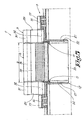
- Figure 1 represents a side-hung window 1 whereby, in this case, two hinges 2 according to the invention are applied.
- such a hinge 2 mainly consists of two blades 3 and 4 and two arms 5 and 6, whereby the first blade 3 is hinge-mounted, in this case by means of two first hinge pens 7, to one far end of the first arm 5 which is provided with a slide 8 on its other far end, which is provided such that it can move in a guide 9 in the second blade 4, and whereby the second arm 6 is hinge-mounted with one far end, by means of a second hinge pen 10, to the second blade 4, and is provided with a slide 11 on its other far end which is provided such that it can move in a guide 12 in the first blade 3, and whereby both aforesaid arms 5 and 6 are mutually hinge-mounted between the first and the second hinge pen 7 and 10 by means of a third hinge pen 13.
- the first blade 3 hereby consists of a fixing plate 14 onto which is fixed a proper blade 15, 16 of the hinge 2 on both far ends, which proper blades 15 and 16 are provided with a bush 17 in which the aforesaid first hinge pens 7 can be fixed.
- the first hinge pens 7 are situated at a mutual distance B in each other's extension in this embodiment.
- this guide 12 consists of a flat plate 20 which is provided with a standing edge 21 on either side, which edges 21 are provided with diagonal edges 22 directed towards each other on their free far ends.
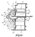
- the above-mentioned flat plate 20 extends in a direction away from the hinge side 19 of the hinge 2 at an angle A, as is represented in figure 2, in relation to a perpendicular through the plane of the above-mentioned first blade 3, which angle is larger than 0° and smaller than 5°.
- the angle A preferably amounts to some 1.5° in the sense of rotation of the hinge 2.
- the fixing plate 14 preferably comprises a U-shaped groove 23 which runs parallel to the longitudinal axis of the different hinge pens 7, 10 and 13, and which is situated at a distance from the first hinge pen 7, equal to the distance between the first and the third hinge pen 7 and 13.
- the second blade 4 consists of a fixing plate 24 which is provided with a guiding element 25, 26 on both its far ends, built in exactly the same manner as the above-mentioned guide 12, and which together form the guide 9.
- This hinge pen 10 has a length which is maximally somewhat shorter than the above-mentioned distance B, and in a closed position of the hinge 2 it is situated on one and the same longitudinal axis as and between the above-mentioned first hinge pens 7.
- the above-mentioned first arms 5 of the hinge 2 in this case each consist of two parts 29 and 30 which are mutually fixed by a bush 31 in which the above-mentioned third hinge pen 13 is provided.
- the parts 29 of the above-mentioned arms 5 are each provided with a bush 32 on their free far ends in which one of the hinge pens 7 is each time provided.
- the second parts 30 of both arms 5 are each provided with the above-mentioned slides 8 on their free far ends, which are provided such in the above-mentioned guide 9 that they can move, and they have a buckle 33.
- the second arm 6 in this case consists of two parts 34 and 35 which are each fixed to a bush 36 with one far end, which bush is positioned between the above-mentioned bushes 31 and through which the above-mentioned hinge pen 13 is provided.
- the first part 34 of this second arm 6 consists of two slats provided at a mutual distance from each other and which each comprise a bush 37 on their free far end.
- These bushes 37 are situated in the extension of the above-mentioned bush 28 on either side, and they are pushed over the above-mentioned second hinge pen 10.
- the second part 35 of the above-mentioned arm 6 is provided with the above-mentioned slide 11 on its free far end, which is provided in the above-mentioned guide 12 such that it can move, and it has a buckle 38 similar to the above-mentioned buckle 33 in the second part 30 of the arm 5.
- the above-mentioned first and second hinge pens 7 and 10 are situated in each other's extension on the hinge side 19 of this hinge 2, whereby the second parts 30 and 35 of the above-mentioned arms 5 and 6 extend mainly diagonally, at an angle A, to the blades 3 and 4 of the hinge 2, and whereby the slides 8 and 11 are situated at a maximum distance from the respective blades 3 and 4 in the guides 9 and 12 concerned.
- the third hinge pen 13 is situated in the above-mentioned groove 23 in the fixing plate 14.
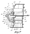
- the hinge pens 7 and 10 are situated, in an open position of the hinge 2, next to each other, whereas the third hinge pen 13 is situated in a position free of any contact with the blades 3 or 4 of the hinge 2.
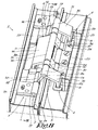
- FIGs 8 and 9 represent a variant in which the hinge pens 7 are held, on either side of the bush 32 of the arm 5, in a bush 16 of the proper blade 15 of the hinge 2, which makes it possible to make the hinge 2 more solid.
- the second hinge pin 10 can be provided in such a manner.
Landscapes
- Engineering & Computer Science (AREA)
- Mechanical Engineering (AREA)
- Hinges (AREA)
Applications Claiming Priority (1)
| Application Number | Priority Date | Filing Date | Title |
|---|---|---|---|
| BE2004/0426A BE1016290A3 (nl) | 2004-09-02 | 2004-09-02 | Scharnier en deur of draairaam waarin zulk een scharnier wordt toegepast. |
Publications (2)
| Publication Number | Publication Date |
|---|---|
| EP1632628A2 true EP1632628A2 (de) | 2006-03-08 |
| EP1632628A3 EP1632628A3 (de) | 2009-10-07 |
Family
ID=34973965
Family Applications (1)
| Application Number | Title | Priority Date | Filing Date |
|---|---|---|---|
| EP05076540A Withdrawn EP1632628A3 (de) | 2004-09-02 | 2005-07-07 | Scharnier und Tür oder seitlich angehängtes Fenster mit einem solchen Scharnier |
Country Status (2)
| Country | Link |
|---|---|
| EP (1) | EP1632628A3 (de) |
| BE (1) | BE1016290A3 (de) |
Cited By (1)
| Publication number | Priority date | Publication date | Assignee | Title |
|---|---|---|---|---|
| RU2597554C2 (ru) * | 2012-02-29 | 2016-09-10 | Симонсверк, Гезелльшафт Мит Бешрэнктер Хафтунг | Дверная петля скрытого расположения между дверной коробкой и дверным полотном |
Family Cites Families (5)
| Publication number | Priority date | Publication date | Assignee | Title |
|---|---|---|---|---|
| US373611A (en) * | 1887-08-30 | 1887-11-22 | Hinge | |
| DE810966C (de) * | 1950-01-17 | 1951-08-16 | Emil Lupp Fa | Unsichtbares Scharnier fuer Klappen aller Art |
| US3368237A (en) * | 1965-03-25 | 1968-02-13 | Bierlich Johannes Harald | Concealed hinge for door, window and similar turnable frames |
| FR1487604A (fr) * | 1966-07-22 | 1967-07-07 | Procede Audoin Alleman Soc D E | Charnière notamment pour l'articulation de panneaux de construction ou autre application |
| ES177247Y (es) * | 1968-10-31 | 1973-04-16 | Stanley Works (Italia), S. R. L. | Charnela para cierres. |
-
2004
- 2004-09-02 BE BE2004/0426A patent/BE1016290A3/nl not_active IP Right Cessation
-
2005
- 2005-07-07 EP EP05076540A patent/EP1632628A3/de not_active Withdrawn
Cited By (1)
| Publication number | Priority date | Publication date | Assignee | Title |
|---|---|---|---|---|
| RU2597554C2 (ru) * | 2012-02-29 | 2016-09-10 | Симонсверк, Гезелльшафт Мит Бешрэнктер Хафтунг | Дверная петля скрытого расположения между дверной коробкой и дверным полотном |
Also Published As
| Publication number | Publication date |
|---|---|
| EP1632628A3 (de) | 2009-10-07 |
| BE1016290A3 (nl) | 2006-07-04 |
Similar Documents
| Publication | Publication Date | Title |
|---|---|---|
| GB2398596A (en) | Folding leaf gate | |
| CA1311259C (en) | Torsion spring powered door | |
| EP1632628A2 (de) | Scharnier und Tür oder seitlich angehängtes Fenster mit einem solchen Scharnier | |
| DE59710995D1 (de) | Band für Türen, Fenster und dergleichen | |
| ATE127570T1 (de) | Dreh-kipp-beschlag für fenster, türen od.dgl. | |
| ATE279629T1 (de) | Beschlagseinheit für ein fenster oder eine tür | |
| ATE389773T1 (de) | Scharnier, insbesondere für eine glastür | |
| EP1580381B1 (de) | Treibstangenbeschlag | |
| US5542721A (en) | Ventilation stop for a sliding window or door | |
| US5194040A (en) | Slot ventilators | |
| ATE271180T1 (de) | Dreh-beschlag oder dreh-kipp-beschlag von fenstern, türen oder dergleichen | |
| ATE472034T1 (de) | Justierbares band für fenster, türen und dergleichen | |
| DE102016123800A1 (de) | Schiebe-Element | |
| ATE164911T1 (de) | Lagerelement eines oberen drehlagers für einen wenigstens drehbar gelagerten flügel eines fensters, einer tür oder dergleichen | |
| CN217151631U (zh) | 一种可调铰链 | |
| EP1835098B1 (de) | Vorrichtung zur Verbindung zweier Teile eines Schließmechanismus in Zusammenhang mit Teilen mit unterschiedlichem Durchmesser eines Flügels eines lukenartigen Kippfensters | |
| SU1036934A2 (ru) | Шахтна вентил ционна дверь | |
| SU966214A1 (ru) | Складчата дверь | |
| JP2647588B2 (ja) | 出窓の折れ雨戸開閉装置 | |
| EP1895083A2 (de) | Schiebetür mit schwenkbarem Notfallöffnungssystem | |
| EP1170449A3 (de) | Kippbeschlag für Fenster, Türen od. dgl. | |
| ATE247761T1 (de) | Flügel für eine tür, ein fenster oder dergleichen | |
| JP2859857B2 (ja) | 両開蝶番 | |
| CA2178019C (en) | Ventilation stop for a sliding window or door | |
| JPH05163864A (ja) | 折れ戸 |
Legal Events
| Date | Code | Title | Description |
|---|---|---|---|
| PUAI | Public reference made under article 153(3) epc to a published international application that has entered the european phase |
Free format text: ORIGINAL CODE: 0009012 |
|
| AK | Designated contracting states |
Kind code of ref document: A2 Designated state(s): AT BE BG CH CY CZ DE DK EE ES FI FR GB GR HU IE IS IT LI LT LU LV MC NL PL PT RO SE SI SK TR |
|
| AX | Request for extension of the european patent |
Extension state: AL BA HR MK YU |
|
| PUAL | Search report despatched |
Free format text: ORIGINAL CODE: 0009013 |
|
| AK | Designated contracting states |
Kind code of ref document: A3 Designated state(s): AT BE BG CH CY CZ DE DK EE ES FI FR GB GR HU IE IS IT LI LT LU LV MC NL PL PT RO SE SI SK TR |
|
| AX | Request for extension of the european patent |
Extension state: AL BA HR MK YU |
|
| AKX | Designation fees paid | ||
| REG | Reference to a national code |
Ref country code: DE Ref legal event code: 8566 |
|
| STAA | Information on the status of an ep patent application or granted ep patent |
Free format text: STATUS: THE APPLICATION IS DEEMED TO BE WITHDRAWN |
|
| 18D | Application deemed to be withdrawn |
Effective date: 20100408 |