EP1631973B1 - Noyau magnetique presentant des capacites de refroidissement et sa methode de fabrication - Google Patents
Noyau magnetique presentant des capacites de refroidissement et sa methode de fabrication Download PDFInfo
- Publication number
- EP1631973B1 EP1631973B1 EP04741775A EP04741775A EP1631973B1 EP 1631973 B1 EP1631973 B1 EP 1631973B1 EP 04741775 A EP04741775 A EP 04741775A EP 04741775 A EP04741775 A EP 04741775A EP 1631973 B1 EP1631973 B1 EP 1631973B1
- Authority
- EP
- European Patent Office
- Prior art keywords
- core
- heat
- powder
- magnetic
- magnetic core
- Prior art date
- Legal status (The legal status is an assumption and is not a legal conclusion. Google has not performed a legal analysis and makes no representation as to the accuracy of the status listed.)
- Expired - Lifetime
Links
- 238000000034 method Methods 0.000 title claims description 11
- 238000001816 cooling Methods 0.000 title description 3
- 229910052751 metal Inorganic materials 0.000 claims abstract description 16
- 239000000843 powder Substances 0.000 claims abstract description 16
- 238000003825 pressing Methods 0.000 claims abstract description 5
- 230000005855 radiation Effects 0.000 claims abstract description 3
- 239000002184 metal Substances 0.000 claims description 15
- 230000017525 heat dissipation Effects 0.000 claims description 10
- 238000004519 manufacturing process Methods 0.000 claims description 5
- 238000001914 filtration Methods 0.000 claims description 4
- 210000001520 comb Anatomy 0.000 claims description 3
- 239000000463 material Substances 0.000 claims description 3
- 238000007493 shaping process Methods 0.000 claims description 3
- 238000005266 casting Methods 0.000 claims 2
- 230000001939 inductive effect Effects 0.000 claims 2
- 238000012546 transfer Methods 0.000 abstract description 6
- 239000011162 core material Substances 0.000 description 82
- 239000000696 magnetic material Substances 0.000 description 7
- 238000004804 winding Methods 0.000 description 7
- 239000007788 liquid Substances 0.000 description 5
- 238000001704 evaporation Methods 0.000 description 4
- 230000008020 evaporation Effects 0.000 description 4
- 230000004907 flux Effects 0.000 description 4
- 239000006247 magnetic powder Substances 0.000 description 4
- 238000010276 construction Methods 0.000 description 3
- 239000011347 resin Substances 0.000 description 3
- 229920005989 resin Polymers 0.000 description 3
- XEEYBQQBJWHFJM-UHFFFAOYSA-N Iron Chemical compound [Fe] XEEYBQQBJWHFJM-UHFFFAOYSA-N 0.000 description 2
- 238000009833 condensation Methods 0.000 description 2
- 230000005494 condensation Effects 0.000 description 2
- 229910000859 α-Fe Inorganic materials 0.000 description 2
- RYGMFSIKBFXOCR-UHFFFAOYSA-N Copper Chemical compound [Cu] RYGMFSIKBFXOCR-UHFFFAOYSA-N 0.000 description 1
- 229910000640 Fe alloy Inorganic materials 0.000 description 1
- 238000004026 adhesive bonding Methods 0.000 description 1
- 239000004411 aluminium Substances 0.000 description 1
- 229910052782 aluminium Inorganic materials 0.000 description 1
- XAGFODPZIPBFFR-UHFFFAOYSA-N aluminium Chemical compound [Al] XAGFODPZIPBFFR-UHFFFAOYSA-N 0.000 description 1
- 239000011230 binding agent Substances 0.000 description 1
- 239000003990 capacitor Substances 0.000 description 1
- 239000000919 ceramic Substances 0.000 description 1
- 230000000052 comparative effect Effects 0.000 description 1
- 150000001875 compounds Chemical class 0.000 description 1
- 239000004020 conductor Substances 0.000 description 1
- 229910052802 copper Inorganic materials 0.000 description 1
- 239000010949 copper Substances 0.000 description 1
- 238000012937 correction Methods 0.000 description 1
- 238000013461 design Methods 0.000 description 1
- 230000001747 exhibiting effect Effects 0.000 description 1
- 230000005484 gravity Effects 0.000 description 1
- 238000009413 insulation Methods 0.000 description 1
- 238000013035 low temperature curing Methods 0.000 description 1
- 239000000203 mixture Substances 0.000 description 1
- 229910000889 permalloy Inorganic materials 0.000 description 1
- 238000012545 processing Methods 0.000 description 1
- 238000005245 sintering Methods 0.000 description 1
- 239000007787 solid Substances 0.000 description 1
- 230000001629 suppression Effects 0.000 description 1
- 239000002699 waste material Substances 0.000 description 1
- XLYOFNOQVPJJNP-UHFFFAOYSA-N water Substances O XLYOFNOQVPJJNP-UHFFFAOYSA-N 0.000 description 1
Images


Classifications
-
- H—ELECTRICITY
- H01—ELECTRIC ELEMENTS
- H01F—MAGNETS; INDUCTANCES; TRANSFORMERS; SELECTION OF MATERIALS FOR THEIR MAGNETIC PROPERTIES
- H01F27/00—Details of transformers or inductances, in general
- H01F27/08—Cooling; Ventilating
- H01F27/085—Cooling by ambient air
-
- H—ELECTRICITY
- H01—ELECTRIC ELEMENTS
- H01F—MAGNETS; INDUCTANCES; TRANSFORMERS; SELECTION OF MATERIALS FOR THEIR MAGNETIC PROPERTIES
- H01F13/00—Apparatus or processes for magnetising or demagnetising
- H01F13/003—Methods and devices for magnetising permanent magnets
-
- H—ELECTRICITY
- H01—ELECTRIC ELEMENTS
- H01F—MAGNETS; INDUCTANCES; TRANSFORMERS; SELECTION OF MATERIALS FOR THEIR MAGNETIC PROPERTIES
- H01F27/00—Details of transformers or inductances, in general
- H01F27/08—Cooling; Ventilating
- H01F27/22—Cooling by heat conduction through solid or powdered fillings
-
- H—ELECTRICITY
- H01—ELECTRIC ELEMENTS
- H01F—MAGNETS; INDUCTANCES; TRANSFORMERS; SELECTION OF MATERIALS FOR THEIR MAGNETIC PROPERTIES
- H01F27/00—Details of transformers or inductances, in general
- H01F27/24—Magnetic cores
- H01F27/255—Magnetic cores made from particles
-
- H—ELECTRICITY
- H01—ELECTRIC ELEMENTS
- H01F—MAGNETS; INDUCTANCES; TRANSFORMERS; SELECTION OF MATERIALS FOR THEIR MAGNETIC PROPERTIES
- H01F17/00—Fixed inductances of the signal type
- H01F17/04—Fixed inductances of the signal type with magnetic core
- H01F17/043—Fixed inductances of the signal type with magnetic core with two, usually identical or nearly identical parts enclosing completely the coil (pot cores)
-
- H—ELECTRICITY
- H01—ELECTRIC ELEMENTS
- H01F—MAGNETS; INDUCTANCES; TRANSFORMERS; SELECTION OF MATERIALS FOR THEIR MAGNETIC PROPERTIES
- H01F37/00—Fixed inductances not covered by group H01F17/00
Definitions
- the present invention relates to magnetic cores having enhanced self-cooling capabilities and, in particular to magnetic cores comprising special elements for dissipating the heat internally produced.
- Magnetic cores as component of impedances, coils and transformers, are used in a number of electrical and electronic applications.
- magnetic cores are used in the manufacturing of impedances, chokes, and transformers in many power or signal processing circuits for the purposes of impedance matching, frequency filtering, as energy tanks in voltage converters, for power factor correction and in numberless other cases.
- US-A-5,768,113 discloses a high power and high voltage power supply is capable of charging one or more capacitors to high voltage.
- the power supply includes a current rectifier circuit for connecting to an AC source, a voltage step-up circuit including at least one controllable electronic switch and a voltage step-up transformer including a primary winding electrically connected to the electronic switch, and a control device for controlling the electronic switch.
- the power supply is organized to chop the current flowing through the primary winding in such a manner as to enable a high voltage to be taken from across the terminal to at least one secondary winding of the transformer.
- the step-up circuit is of a non-resonant type.
- the transformer core has heat dissipation features permanently fixed to its outer surface.
- Magnetic coils and the associated cores are generally present in EMC filters, and in most noise-suppression filters. Due to their comparative bulk, Magnetic component contribute heavily to the size and cost of such filtering devices.
- magnetic cores In many cases, and in particular in medium and high frequency applications with moderate or high core losses, it is customary to produce magnetic cores from magnetic metallic powders, typically iron or permalloy powders, or other magnetic powders, by a process of pressing a mixture of magnetic powder and an adequate binding and insulating phase, into a die of the desired form. The powder and the binding phase are compacted together by the action of heat and pressure into a solid core having the desired shape.
- magnetic metallic powders typically iron or permalloy powders, or other magnetic powders
- magnetic cores can be produced by magnetic powder alone, by a sintering process.
- magnetic cores are cast at lower temperature and pressure, by adopting an appropriate resin binder, for example a two-component hardening compound, another chemically curable resin, or a low-temperature curing resin.
- an appropriate resin binder for example a two-component hardening compound, another chemically curable resin, or a low-temperature curing resin.
- Other magnetic core types comprise laminated cores, mostly employed for applications at mains frequency, and ceramic ferrite cores.
- the internally produced heat must however be transferred to the outside to avoid that the temperature exceeds the thermal limit of the coil insulation or the Curie point of the magnetic material. Due to the finite core heat-transfer capability, core losses are often a major limiting factor in the power rating of a magnetic component.
- Magnetic cores 10 are usually manufactured in a variety of shapes, some of which are represented on figure 1. Core shapes are generally designed with the aim of simplifying coil winding and/or of using the magnetic material in the most efficient way. The designer tries therefore to place the magnetic material in high flux zones, and regards regions of magnetic material in which the flux is sensibly lower then average as an unnecessary waste.
- the known cores 10 represented on figure 1 are an example of this way of designing. While these cores use a minimal amount of magnetic material, the outer surface available for the heat exchange is necessarily very low. These cores are therefore easily overheated, because the heat dissipation of the core losses is very inefficient in this design. As a consequence, in many applications where core losses are moderate or high, the core dimensioning factor will be the power dissipation rather than the maximum available magnetic flux.
- An object of the present invention is to provide a magnetic core in which the heat losses are efficiently transferred to the outside, and therefore a magnetic core allowing the construction of more compact, more powerful coils and magnetic components.
- a further object of the present invention is to provide a filter, and a coil therefore, exhibiting smaller size and lower cost.
- the shape of the core is chosen in order to enhance heat dissipation.
- the outer surface of the core 10 is equipped with fin-like structures in order to increase heat dissipation.
- Figures 2a and 2b represent an example of an E-core 10 provided with a series of heat fins 40 on the other surface.
- the heat fins 40 are integrally realized together with the core 10, by appropriately shaping the die or the mould in which the metal powder is pressed or cast.
- the magnetic material in the heat fins 40 may play little or no role as far as the magnetic circuit is concerned, yet the fins 40 significantly improve heat convection and radiation from the core 10 to the outside.
- the cores of figure 2a will often lead, in presence of core losses, to a more compact and economical construction than the known cores 10 of the figure 1.
- This invention is limited to powder cores, but the fins 40 could equally be added to ferrite cores, or to laminated cores, or to magnetic elements of other magnetic materials with which radiating fins can be integrally realized.
- the same heat-dissipating fins 40 are realized on the outer surface of a pot-shaped core 10. It is clear that similar variant embodiments are also possible for any other usual core shape, for example for C-cores, ring, flat, drum or rod cores, and for all variations and combinations thereof.
- the present invention should not be limited to the provision of parallel fins as described in the above non-limitative examples, but comprises as well other geometrical structures like ribs, slots, protrusions, nooks, combs, fingers, and in general any shape providing cavities and protrusions for increasing the available external surface of the core and the heat dissipation therefrom.
- the magnetic core according to the invention comprises heat-conductive inserts 50, permanently attached to or inserted in the core 10, for conducting and dissipating the heat generated in the core 10 as a consequence of the magnetic losses therein.
- heat conductive inserts 50 can for example be realized from pre-punched metal sheets, inserted in the die or in the mould before the magnetic powder is added and which become then permanently incorporated in the powder core.
- the protruding part of the metal inserts 50 acts as radiating fins, thus increasing the heat dissipation from the core 10.
- the metal inserts 50 can be inserted and integrated in the core 10 after the constitution of the core 10, for example by gluing, pressing, screwing, or by any other assembly technique.
- the shape of the sheets will be chosen in order to achieve a large contact area with the core material, and the sheet orientation and thickness will be adapted in order to minimize the induced eddy currents.
- the sheets may be realized of high thermal conductivity material, like aluminium or copper.
- thermoelectric insert 50 consists of metal rods or of metal wires or of a metallic mesh.
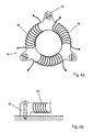
- Figures 6a and 6b represent an alternative embodiment of the present invention according to which a ring core 10 comprises metallic bushes 90 for fixing the wound core 10 to a heat sink.
- the metallic bushes 90 are permanently inserted in the core 10, and produce three ear pads, by which the core 10 can conveniently be mounted on the heat sink. The internally generated heat flows therefore from the core 10 through the bushes 90 to the heat sink, by thermal conduction.
- This embodiment of the present invention lends itself to several variants, in which the cylindrical bushes 90 are replaced by other mounting and heat-conduction inserts, like for example metallic profiles or fixation plaques.
- a pot core 10, on which a winding 20 is realized has permanently inserted a heat pipe 80.
- the heat pipe 80 is in thermal contact with the core 10, and comprises an internal conduit (not represented) partially filled with a volatile liquid, for example water in a low-pressure tight chamber.
- the heat contact between the heat pipe 80 and the core 10 can be enhanced for example by providing a series of ribs on the former (not represented).
- the volatile liquid continuously evaporates in the part of the heat pipe 80 in contact with the hot core 10 and condensates in the cold outer part thermally connected with the large radiator 81. From the cold end of the pipe 80 the liquid drips back to the core in a continuous cycle.
- the heat transfer along the heat pipe 80 comprises the four following processes, all taking place in a continuous cycle:
- the heat pipe 80 can be permanently integrated in the core 10 during its fabrication, or permanently mounted to it in a further fabrication phase.
- the radiator 81 could be substituted by a heat sink.
- the heat pipe 80 provides efficient conduction of the heat to the heat sink.
- one or more conductors are wound around one of the magnetic cores described above, and the resulting coil is incorporated in a filter circuit, for example a power filter for electromagnetic compatibility, or another sort of filter or noise-suppression circuit.
- a filter circuit for example a power filter for electromagnetic compatibility, or another sort of filter or noise-suppression circuit.
- the coil so produced thanks to its small size and high loss tolerance is particularly suitable for such filtering applications, particularly for EMC filters at mains voltage.
- the coil thus fashioned may comprise multiple windings, for example in the case of a filter for a multiphase power system.
- the present invention also provides longitudinal coils and current-compensated coils with improved cooling capability.
Landscapes
- Engineering & Computer Science (AREA)
- Power Engineering (AREA)
- Coils Or Transformers For Communication (AREA)
- Molds, Cores, And Manufacturing Methods Thereof (AREA)
- Soft Magnetic Materials (AREA)
- Cooling Or The Like Of Electrical Apparatus (AREA)
- Powder Metallurgy (AREA)
Claims (10)
- Noyau magnétique (10) pour un filtre de compatibilité électromagnétique de puissance, ledit noyau (10) consistant en une poudre de métal,
caractérisé en ce que
le noyau (10) comprend une surface externe et a des caractéristiques de dissipation de chaleur (40, 80, 81, 90) formées intégralement avec ledit noyau de poudre (10) ou des insertions conductrices de chaleur (50) incorporées de façon permanente dans ledit noyau de poudre (10) pour en augmenter la dissipation de chaleur. - Le noyau magnétique de la revendication 1, dans lequel lesdites caractéristiques de dissipation augmentent ladite surface externe du noyau (10) et comprennent au moins une des formes suivantes: des nervures, protrusions, des ailerons (40), des doigts, des fentes, des alcôves et opercules, ou n'importe quelle forme fournissant des cavités et des protrusions.
- Le noyau magnétique de la revendication 1, dans lequel les insertions conductrices de chaleur (50) comprennent du matériau préperforé, des tiges en métal, des fils en métal ou une maille métallique.
- Le noyau magnétique de la revendication 1, dans lequel lesdites caractéristiques de dissipation s'étendent (10) vers l'extérieur dudit noyau pour dissiper la chaleur par convection ou radiation.
- Un composant électrique inductif, comprenant au moins un noyau magnétique (10) selon l'une des revendications précédentes.
- Un filtre de puissance pour compatibilité électromagnétique, comprenant un composant inductif selon la revendication 5.
- Le filtre de puissance selon la revendication 6, dans lequel ledit filtre est adapté pour filtrer un bruit superposé à une ligne d'alimentation principale.
- Procédé pour produire un noyau magnétique (10) pour un filtre de compatibilité électrique de puissance selon l'une des revendications 1 à 4, dans lequel ledit noyau (10) contient une poudre de métal, la méthode comprenant les étapes de• fournir un moule à coulée sous pression ou compression;• ajouter de la poudre métallique, la méthode étant caractérisée par les étapes de• façonner le moule à coulée ou de pressage dans la forme des caractéristiques de dissipation de chaleur (40, 50, 80, 81, 90) ou insérer dans le moule à coulée ou de pressage des insertions conductrices de chaleur (50) et• former intégralement lesdites caractéristiques de dissipation de chaleur (40, 50, 80, 81, 90) avec ledit noyau en poudre (10) ou incorporer de manière permanente lesdites insertions conductrices de chaleur (50) dans ledit noyau en poudre (10) dans l'étape de presser ou verser la poudre métallique.
- Procédé selon la revendication 8, comprenant l'étape de façonnage du moule à coulée ou de pressage dans la forme de nervures, protrusions, ailerons (40), doigts, alcôves ou opercules ou n'importe quelle forme fournissant des cavités et protrusions.
- Procédé selon la revendication 8, comprenant l'étape de réaliser lesdites insertions conductrices de chaleur (50) à partir de matériau préperforé, de tiges en métal, de fils en métal ou une maille métallique.
Priority Applications (1)
| Application Number | Priority Date | Filing Date | Title |
|---|---|---|---|
| EP04741775A EP1631973B1 (fr) | 2003-06-10 | 2004-06-10 | Noyau magnetique presentant des capacites de refroidissement et sa methode de fabrication |
Applications Claiming Priority (3)
| Application Number | Priority Date | Filing Date | Title |
|---|---|---|---|
| EP03101688 | 2003-06-10 | ||
| EP04741775A EP1631973B1 (fr) | 2003-06-10 | 2004-06-10 | Noyau magnetique presentant des capacites de refroidissement et sa methode de fabrication |
| PCT/EP2004/051085 WO2004112064A1 (fr) | 2003-06-10 | 2004-06-10 | Noyau magnetique et dispositif presentant des capacites de refroidissement |
Publications (2)
| Publication Number | Publication Date |
|---|---|
| EP1631973A1 EP1631973A1 (fr) | 2006-03-08 |
| EP1631973B1 true EP1631973B1 (fr) | 2007-11-07 |
Family
ID=33547698
Family Applications (1)
| Application Number | Title | Priority Date | Filing Date |
|---|---|---|---|
| EP04741775A Expired - Lifetime EP1631973B1 (fr) | 2003-06-10 | 2004-06-10 | Noyau magnetique presentant des capacites de refroidissement et sa methode de fabrication |
Country Status (4)
| Country | Link |
|---|---|
| EP (1) | EP1631973B1 (fr) |
| AT (1) | ATE377834T1 (fr) |
| DE (1) | DE602004009924T2 (fr) |
| WO (1) | WO2004112064A1 (fr) |
Cited By (1)
| Publication number | Priority date | Publication date | Assignee | Title |
|---|---|---|---|---|
| EP4390989A4 (fr) * | 2021-09-29 | 2024-12-04 | Mitsubishi Heavy Industries Thermal Systems, Ltd. | Réacteur |
Families Citing this family (5)
| Publication number | Priority date | Publication date | Assignee | Title |
|---|---|---|---|---|
| EP2463871B1 (fr) * | 2010-12-07 | 2017-06-14 | ABB Schweiz AG | Noyau de transformateur amorphe |
| ES2530055T3 (es) * | 2011-02-16 | 2015-02-26 | Abb Technology Ag | Sistema de refrigeración para transformadores secos |
| JP6460329B2 (ja) * | 2015-02-27 | 2019-01-30 | 株式会社オートネットワーク技術研究所 | リアクトル |
| FR3045923B1 (fr) * | 2015-12-17 | 2021-05-07 | Commissariat Energie Atomique | Noyaux d'inductance monolithique integrant un drain thermique |
| FR3045921B1 (fr) * | 2015-12-17 | 2019-07-12 | Commissariat A L'energie Atomique Et Aux Energies Alternatives | Circuit a inductance integrant une fonction de gestion thermique passive |
Family Cites Families (4)
| Publication number | Priority date | Publication date | Assignee | Title |
|---|---|---|---|---|
| JPS6194310A (ja) * | 1984-10-15 | 1986-05-13 | Kansai Electric Power Co Inc:The | 電気機器用鉄心冷却装置 |
| FR2740631B1 (fr) * | 1995-10-31 | 1998-01-16 | Eurofeedback Sa | Alimentation a haute tension et de forte puissance |
| JPH10163022A (ja) * | 1996-12-03 | 1998-06-19 | Minebea Co Ltd | 放熱面積を拡大した積層組立体 |
| DE50014291D1 (de) * | 1999-10-29 | 2007-06-14 | Schaffner Emv Ag | Verwendung eines drei-Phasen-Filters mit Nullleiter |
-
2004
- 2004-06-10 DE DE602004009924T patent/DE602004009924T2/de not_active Expired - Lifetime
- 2004-06-10 WO PCT/EP2004/051085 patent/WO2004112064A1/fr active IP Right Grant
- 2004-06-10 EP EP04741775A patent/EP1631973B1/fr not_active Expired - Lifetime
- 2004-06-10 AT AT04741775T patent/ATE377834T1/de not_active IP Right Cessation
Cited By (1)
| Publication number | Priority date | Publication date | Assignee | Title |
|---|---|---|---|---|
| EP4390989A4 (fr) * | 2021-09-29 | 2024-12-04 | Mitsubishi Heavy Industries Thermal Systems, Ltd. | Réacteur |
Also Published As
| Publication number | Publication date |
|---|---|
| WO2004112064A1 (fr) | 2004-12-23 |
| DE602004009924D1 (de) | 2007-12-20 |
| DE602004009924T2 (de) | 2008-08-28 |
| EP1631973A1 (fr) | 2006-03-08 |
| ATE377834T1 (de) | 2007-11-15 |
Similar Documents
| Publication | Publication Date | Title |
|---|---|---|
| US5686006A (en) | Induction cooker with coil support having spiral-shaped housing for spiral coil | |
| US7911308B2 (en) | Low thermal impedance conduction cooled magnetics | |
| EP2989645B1 (fr) | Système de gestion thermique pour inducteurs smc | |
| TWI379329B (en) | Transformer structure | |
| JP6195627B2 (ja) | 電磁誘導機器 | |
| WO2009042232A1 (fr) | Transformateur magnétique à optimisation thermique | |
| CN103003896A (zh) | 电抗器及线圈构件 | |
| CN101447280B (zh) | 电子装置的扼流圈 | |
| WO2014086948A2 (fr) | Ensemble de transformateur | |
| JP2007235054A (ja) | ヒートシンクおよびヒートシンク付きチョークコイルならびにその製造方法 | |
| JP4775108B2 (ja) | パワー電子機器 | |
| EP1631973B1 (fr) | Noyau magnetique presentant des capacites de refroidissement et sa methode de fabrication | |
| US3179908A (en) | Heat exchange means for electromagnetic devices | |
| US20230014778A1 (en) | Magnetic component structure with thermal conductive filler | |
| JP2011124242A (ja) | リアクトル装置 | |
| JP6393212B2 (ja) | 電力変換装置 | |
| JPS6161525B2 (fr) | ||
| CN108475575B (zh) | 包括含有被动热管理装置的至少一个感应器的电子设备 | |
| CN214336486U (zh) | 单相共轭电抗器以及三相共轭电抗器 | |
| US11778773B2 (en) | Choke structure with water cooling | |
| JP6221927B2 (ja) | リアクトル | |
| EP4254445A1 (fr) | Composant magnétique de puissance | |
| CN218768948U (zh) | 磁性元件的外壳 | |
| JP2009253105A (ja) | リアクトル装置 | |
| CN216218505U (zh) | 一种扼流圈散热结构及空调器 |
Legal Events
| Date | Code | Title | Description |
|---|---|---|---|
| PUAI | Public reference made under article 153(3) epc to a published international application that has entered the european phase |
Free format text: ORIGINAL CODE: 0009012 |
|
| 17P | Request for examination filed |
Effective date: 20051208 |
|
| AK | Designated contracting states |
Kind code of ref document: A1 Designated state(s): AT BE BG CH CY CZ DE DK EE ES FI FR GB GR HU IE IT LI LU MC NL PL PT RO SE SI SK TR |
|
| DAX | Request for extension of the european patent (deleted) | ||
| 17Q | First examination report despatched |
Effective date: 20061002 |
|
| RIN1 | Information on inventor provided before grant (corrected) |
Inventor name: KULL, PETER Inventor name: SIPPOLA, MIKA MATTI |
|
| GRAP | Despatch of communication of intention to grant a patent |
Free format text: ORIGINAL CODE: EPIDOSNIGR1 |
|
| RIC1 | Information provided on ipc code assigned before grant |
Ipc: H01F 41/02 20060101ALI20070710BHEP Ipc: H02J 3/18 20060101ALI20070710BHEP Ipc: H01F 27/22 20060101AFI20070710BHEP Ipc: H01F 27/24 20060101ALI20070710BHEP |
|
| RTI1 | Title (correction) |
Free format text: MAGNETIC CORE WITH COOLING CAPABILITIES AND METHOD FOR ITS PRODUCING |
|
| GRAS | Grant fee paid |
Free format text: ORIGINAL CODE: EPIDOSNIGR3 |
|
| GRAA | (expected) grant |
Free format text: ORIGINAL CODE: 0009210 |
|
| STAA | Information on the status of an ep patent application or granted ep patent |
Free format text: STATUS: THE PATENT HAS BEEN GRANTED |
|
| AK | Designated contracting states |
Kind code of ref document: B1 Designated state(s): AT BE BG CH CY CZ DE DK EE ES FI FR GB GR HU IE IT LI LU MC NL PL PT RO SE SI SK TR |
|
| REG | Reference to a national code |
Ref country code: GB Ref legal event code: FG4D |
|
| REG | Reference to a national code |
Ref country code: IE Ref legal event code: FG4D |
|
| REG | Reference to a national code |
Ref country code: CH Ref legal event code: EP |
|
| REF | Corresponds to: |
Ref document number: 602004009924 Country of ref document: DE Date of ref document: 20071220 Kind code of ref document: P |
|
| PG25 | Lapsed in a contracting state [announced via postgrant information from national office to epo] |
Ref country code: ES Free format text: LAPSE BECAUSE OF FAILURE TO SUBMIT A TRANSLATION OF THE DESCRIPTION OR TO PAY THE FEE WITHIN THE PRESCRIBED TIME-LIMIT Effective date: 20080218 Ref country code: NL Free format text: LAPSE BECAUSE OF FAILURE TO SUBMIT A TRANSLATION OF THE DESCRIPTION OR TO PAY THE FEE WITHIN THE PRESCRIBED TIME-LIMIT Effective date: 20071107 Ref country code: SE Free format text: LAPSE BECAUSE OF FAILURE TO SUBMIT A TRANSLATION OF THE DESCRIPTION OR TO PAY THE FEE WITHIN THE PRESCRIBED TIME-LIMIT Effective date: 20080207 Ref country code: LI Free format text: LAPSE BECAUSE OF FAILURE TO SUBMIT A TRANSLATION OF THE DESCRIPTION OR TO PAY THE FEE WITHIN THE PRESCRIBED TIME-LIMIT Effective date: 20071107 Ref country code: CH Free format text: LAPSE BECAUSE OF FAILURE TO SUBMIT A TRANSLATION OF THE DESCRIPTION OR TO PAY THE FEE WITHIN THE PRESCRIBED TIME-LIMIT Effective date: 20071107 |
|
| NLV1 | Nl: lapsed or annulled due to failure to fulfill the requirements of art. 29p and 29m of the patents act | ||
| PG25 | Lapsed in a contracting state [announced via postgrant information from national office to epo] |
Ref country code: SI Free format text: LAPSE BECAUSE OF FAILURE TO SUBMIT A TRANSLATION OF THE DESCRIPTION OR TO PAY THE FEE WITHIN THE PRESCRIBED TIME-LIMIT Effective date: 20071107 Ref country code: PL Free format text: LAPSE BECAUSE OF FAILURE TO SUBMIT A TRANSLATION OF THE DESCRIPTION OR TO PAY THE FEE WITHIN THE PRESCRIBED TIME-LIMIT Effective date: 20071107 Ref country code: BG Free format text: LAPSE BECAUSE OF FAILURE TO SUBMIT A TRANSLATION OF THE DESCRIPTION OR TO PAY THE FEE WITHIN THE PRESCRIBED TIME-LIMIT Effective date: 20080207 |
|
| REG | Reference to a national code |
Ref country code: CH Ref legal event code: PL |
|
| PG25 | Lapsed in a contracting state [announced via postgrant information from national office to epo] |
Ref country code: AT Free format text: LAPSE BECAUSE OF FAILURE TO SUBMIT A TRANSLATION OF THE DESCRIPTION OR TO PAY THE FEE WITHIN THE PRESCRIBED TIME-LIMIT Effective date: 20071107 |
|
| PG25 | Lapsed in a contracting state [announced via postgrant information from national office to epo] |
Ref country code: DK Free format text: LAPSE BECAUSE OF FAILURE TO SUBMIT A TRANSLATION OF THE DESCRIPTION OR TO PAY THE FEE WITHIN THE PRESCRIBED TIME-LIMIT Effective date: 20071107 Ref country code: CZ Free format text: LAPSE BECAUSE OF FAILURE TO SUBMIT A TRANSLATION OF THE DESCRIPTION OR TO PAY THE FEE WITHIN THE PRESCRIBED TIME-LIMIT Effective date: 20071107 |
|
| EN | Fr: translation not filed | ||
| PG25 | Lapsed in a contracting state [announced via postgrant information from national office to epo] |
Ref country code: RO Free format text: LAPSE BECAUSE OF FAILURE TO SUBMIT A TRANSLATION OF THE DESCRIPTION OR TO PAY THE FEE WITHIN THE PRESCRIBED TIME-LIMIT Effective date: 20071107 Ref country code: BE Free format text: LAPSE BECAUSE OF FAILURE TO SUBMIT A TRANSLATION OF THE DESCRIPTION OR TO PAY THE FEE WITHIN THE PRESCRIBED TIME-LIMIT Effective date: 20071107 Ref country code: SK Free format text: LAPSE BECAUSE OF FAILURE TO SUBMIT A TRANSLATION OF THE DESCRIPTION OR TO PAY THE FEE WITHIN THE PRESCRIBED TIME-LIMIT Effective date: 20071107 |
|
| PLBE | No opposition filed within time limit |
Free format text: ORIGINAL CODE: 0009261 |
|
| STAA | Information on the status of an ep patent application or granted ep patent |
Free format text: STATUS: NO OPPOSITION FILED WITHIN TIME LIMIT |
|
| PG25 | Lapsed in a contracting state [announced via postgrant information from national office to epo] |
Ref country code: PT Free format text: LAPSE BECAUSE OF FAILURE TO SUBMIT A TRANSLATION OF THE DESCRIPTION OR TO PAY THE FEE WITHIN THE PRESCRIBED TIME-LIMIT Effective date: 20080407 |
|
| 26N | No opposition filed |
Effective date: 20080808 |
|
| PG25 | Lapsed in a contracting state [announced via postgrant information from national office to epo] |
Ref country code: FR Free format text: LAPSE BECAUSE OF FAILURE TO SUBMIT A TRANSLATION OF THE DESCRIPTION OR TO PAY THE FEE WITHIN THE PRESCRIBED TIME-LIMIT Effective date: 20080822 |
|
| PG25 | Lapsed in a contracting state [announced via postgrant information from national office to epo] |
Ref country code: MC Free format text: LAPSE BECAUSE OF NON-PAYMENT OF DUE FEES Effective date: 20080630 Ref country code: GR Free format text: LAPSE BECAUSE OF FAILURE TO SUBMIT A TRANSLATION OF THE DESCRIPTION OR TO PAY THE FEE WITHIN THE PRESCRIBED TIME-LIMIT Effective date: 20080208 |
|
| GBPC | Gb: european patent ceased through non-payment of renewal fee |
Effective date: 20080610 |
|
| PG25 | Lapsed in a contracting state [announced via postgrant information from national office to epo] |
Ref country code: FI Free format text: LAPSE BECAUSE OF FAILURE TO SUBMIT A TRANSLATION OF THE DESCRIPTION OR TO PAY THE FEE WITHIN THE PRESCRIBED TIME-LIMIT Effective date: 20071107 |
|
| PG25 | Lapsed in a contracting state [announced via postgrant information from national office to epo] |
Ref country code: IE Free format text: LAPSE BECAUSE OF NON-PAYMENT OF DUE FEES Effective date: 20080610 Ref country code: EE Free format text: LAPSE BECAUSE OF FAILURE TO SUBMIT A TRANSLATION OF THE DESCRIPTION OR TO PAY THE FEE WITHIN THE PRESCRIBED TIME-LIMIT Effective date: 20071107 |
|
| PG25 | Lapsed in a contracting state [announced via postgrant information from national office to epo] |
Ref country code: GB Free format text: LAPSE BECAUSE OF NON-PAYMENT OF DUE FEES Effective date: 20080610 |
|
| PG25 | Lapsed in a contracting state [announced via postgrant information from national office to epo] |
Ref country code: CY Free format text: LAPSE BECAUSE OF FAILURE TO SUBMIT A TRANSLATION OF THE DESCRIPTION OR TO PAY THE FEE WITHIN THE PRESCRIBED TIME-LIMIT Effective date: 20071107 |
|
| PG25 | Lapsed in a contracting state [announced via postgrant information from national office to epo] |
Ref country code: HU Free format text: LAPSE BECAUSE OF FAILURE TO SUBMIT A TRANSLATION OF THE DESCRIPTION OR TO PAY THE FEE WITHIN THE PRESCRIBED TIME-LIMIT Effective date: 20080508 Ref country code: LU Free format text: LAPSE BECAUSE OF NON-PAYMENT OF DUE FEES Effective date: 20080610 |
|
| PG25 | Lapsed in a contracting state [announced via postgrant information from national office to epo] |
Ref country code: TR Free format text: LAPSE BECAUSE OF FAILURE TO SUBMIT A TRANSLATION OF THE DESCRIPTION OR TO PAY THE FEE WITHIN THE PRESCRIBED TIME-LIMIT Effective date: 20071107 |
|
| PG25 | Lapsed in a contracting state [announced via postgrant information from national office to epo] |
Ref country code: IT Free format text: LAPSE BECAUSE OF NON-PAYMENT OF DUE FEES Effective date: 20080630 |
|
| PGFP | Annual fee paid to national office [announced via postgrant information from national office to epo] |
Ref country code: DE Payment date: 20150619 Year of fee payment: 12 |
|
| REG | Reference to a national code |
Ref country code: DE Ref legal event code: R119 Ref document number: 602004009924 Country of ref document: DE |
|
| PG25 | Lapsed in a contracting state [announced via postgrant information from national office to epo] |
Ref country code: DE Free format text: LAPSE BECAUSE OF NON-PAYMENT OF DUE FEES Effective date: 20170103 |