EP1631470B1 - Entrainement pour un engin mobile - Google Patents
Entrainement pour un engin mobile Download PDFInfo
- Publication number
- EP1631470B1 EP1631470B1 EP04739466A EP04739466A EP1631470B1 EP 1631470 B1 EP1631470 B1 EP 1631470B1 EP 04739466 A EP04739466 A EP 04739466A EP 04739466 A EP04739466 A EP 04739466A EP 1631470 B1 EP1631470 B1 EP 1631470B1
- Authority
- EP
- European Patent Office
- Prior art keywords
- output flange
- drive
- bearing
- planet carrier
- pin
- Prior art date
- Legal status (The legal status is an assumption and is not a legal conclusion. Google has not performed a legal analysis and makes no representation as to the accuracy of the status listed.)
- Expired - Lifetime
Links
- 238000005553 drilling Methods 0.000 abstract 1
- 230000005540 biological transmission Effects 0.000 description 3
- 238000011109 contamination Methods 0.000 description 3
- 238000009434 installation Methods 0.000 description 2
- 239000000314 lubricant Substances 0.000 description 2
- 238000007789 sealing Methods 0.000 description 2
- 230000001133 acceleration Effects 0.000 description 1
- 238000001816 cooling Methods 0.000 description 1
- 238000012423 maintenance Methods 0.000 description 1
- 238000010079 rubber tapping Methods 0.000 description 1
Images
Classifications
-
- B—PERFORMING OPERATIONS; TRANSPORTING
- B60—VEHICLES IN GENERAL
- B60K—ARRANGEMENT OR MOUNTING OF PROPULSION UNITS OR OF TRANSMISSIONS IN VEHICLES; ARRANGEMENT OR MOUNTING OF PLURAL DIVERSE PRIME-MOVERS IN VEHICLES; AUXILIARY DRIVES FOR VEHICLES; INSTRUMENTATION OR DASHBOARDS FOR VEHICLES; ARRANGEMENTS IN CONNECTION WITH COOLING, AIR INTAKE, GAS EXHAUST OR FUEL SUPPLY OF PROPULSION UNITS IN VEHICLES
- B60K17/00—Arrangement or mounting of transmissions in vehicles
- B60K17/04—Arrangement or mounting of transmissions in vehicles characterised by arrangement, location or kind of gearing
- B60K17/043—Transmission unit disposed in on near the vehicle wheel, or between the differential gear unit and the wheel
- B60K17/046—Transmission unit disposed in on near the vehicle wheel, or between the differential gear unit and the wheel with planetary gearing having orbital motion
-
- F—MECHANICAL ENGINEERING; LIGHTING; HEATING; WEAPONS; BLASTING
- F16—ENGINEERING ELEMENTS AND UNITS; GENERAL MEASURES FOR PRODUCING AND MAINTAINING EFFECTIVE FUNCTIONING OF MACHINES OR INSTALLATIONS; THERMAL INSULATION IN GENERAL
- F16D—COUPLINGS FOR TRANSMITTING ROTATION; CLUTCHES; BRAKES
- F16D55/00—Brakes with substantially-radial braking surfaces pressed together in axial direction, e.g. disc brakes
- F16D55/24—Brakes with substantially-radial braking surfaces pressed together in axial direction, e.g. disc brakes with a plurality of axially-movable discs, lamellae, or pads, pressed from one side towards an axially-located member
- F16D55/26—Brakes with substantially-radial braking surfaces pressed together in axial direction, e.g. disc brakes with a plurality of axially-movable discs, lamellae, or pads, pressed from one side towards an axially-located member without self-tightening action
- F16D55/36—Brakes with a plurality of rotating discs all lying side by side
- F16D55/40—Brakes with a plurality of rotating discs all lying side by side actuated by a fluid-pressure device arranged in or one the brake
-
- F—MECHANICAL ENGINEERING; LIGHTING; HEATING; WEAPONS; BLASTING
- F16—ENGINEERING ELEMENTS AND UNITS; GENERAL MEASURES FOR PRODUCING AND MAINTAINING EFFECTIVE FUNCTIONING OF MACHINES OR INSTALLATIONS; THERMAL INSULATION IN GENERAL
- F16H—GEARING
- F16H57/00—General details of gearing
- F16H57/08—General details of gearing of gearings with members having orbital motion
- F16H57/10—Braking arrangements
Definitions
- the invention relates to a drive for a mobile vehicle according to the closer defined in the preamble of claim 1.
- Generic drives are used to drive vehicle wheels, especially for work machines such as wheeled excavators or wheel loaders. It is on the one hand of importance to brake the vehicle directly to turn off in the braked state, an additional movement of the vehicle by the teeth clearance of a, a service brake downstream reduction gear stage, and on the other hand of importance to protect this brake from contamination. Likewise, it is important to design the wheel bearings, over which the vehicle wheels are mounted, so that a sufficient service life can be achieved even with the high vehicle weights of the working machines. It is also important to be able to carry out maintenance work on the drives without removing the axle from the vehicle.
- EP 0 979 365 B1 which shows all the features of the preamble of independent claim 1, discloses a vehicle transmission with integrated, cooled brake, in which the output flange is mounted directly in the housing via wheel bearings and is non-rotatably connected to the planet carrier via a tooth system.
- the inner rotating lamellae of a multi-disc brake are arranged, via which the planet carrier is connectable to the rotationally fixed housing.
- the planet carrier has a pin, which protrudes into a bore of the output flange, wherein the rotationally fixed connection between the output flange and the pin via a driving toothing takes place.
- the US 6,090,006 discloses a vehicle transmission for driving the vehicle wheels, wherein the output flange is mounted directly in the housing via two wheel bearings and the pin of the output flange is rotatably held in a bore of the planet carrier via a driving teeth. At the radially outer region of the planet carrier are the rotating lamellae of a multi-disc brake, via which the planet carrier is rotatably connected to the housing. A disassembly of the output flange is very expensive here.
- EP 1 234 993 A1 discloses a vehicle transmission for driving the vehicle wheels, in which the output flange are mounted in the housing via a centering pin in the planet carrier and the planet carrier via two wheel bearings. To connect the output flange with the planet carrier rotatably, the output flange is bolted via axially arranged screws with the planet carrier.
- the US 6,530,859 B2 discloses a planetary gear in which an output flange is rotatably connected via a driving teeth with an output shaft and the output shaft via a first bearing in the housing and the planet carrier via a second bearing are mounted in the housing and between the radially outer portion of the output shaft and a bore in the planet carrier a centering is arranged, which centers the planet carrier on the output shaft.
- a centering is arranged, which centers the planet carrier on the output shaft.
- a centering is arranged, which centers the planet carrier on the output shaft.
- a disc with a Arranged connecting element via which the planet carrier is axially connectable to the output shaft.
- a disassembly of the output shaft is expensive.
- the US 4,424,874 discloses in particular in FIG. 4 a drive for a mobile vehicle, in which a multi-disc brake disposed between the inner central wheel and the rotationally fixed housing and the output flange are rotatably connected via a driving teeth with the planet carrier, and the output flange via a first bearing are mounted in the housing and the planet carrier via a second bearing in the housing, and the output flange via a nut, which is arranged directly adjacent to the inner central wheel, is connected in the axial direction with the planet carrier.
- the disassembly and assembly of the drive is difficult, since the planetary gear must be dismantled to adjust the wheel bearings.
- the present invention has for its object to provide a drive for mobile vehicles, in which the output directly via a multi-disc brake is braked, in which the wheel bearings have sufficient life and the drive is easy to disassemble.
- the object is achieved with a, including the characterizing features of the main claim, generic drive for mobile vehicles.
- the drive for mobile vehicles on a driven flange which is mounted in the housing via a first bearing.
- the planet carrier is also mounted in the housing via a second bearing.
- the first and the second bearing are arranged in the same housing part.
- the planet carrier has a pin pointing in the direction of the output flange, which protrudes into a bore of the output flange, and via which the output flange is rotatably connected to the planet carrier.
- the inner ring of the second bearing is supported on the one hand in the planet carrier and on the other hand in the axial direction on the output flange, whereby the inner ring of the second bearing is fixed in the axial direction by the output flange and the planet carrier.
- the output flange is centered on the planet carrier in the radial direction.
- the output flange facing the end of the pin of the planet carrier of the output flange and the pin are formed so that a second centering of the output flange takes place on the pin of the planet carrier.
- this centering via a centering, which is located between the pin and the output flange.
- this centering bush is cup-shaped, whereby the output flange fixed on the pin of the planet carrier in the axial direction can be by the cup-shaped socket via axial connecting elements, such as screws, on the one hand clamped on the pin and on the other hand is supported in the axial direction in the output flange.
- the output flange is centered over two spaced centering on the planet carrier in the radial direction, effectively prevents tilting of the planet carrier in the output flange, whereby the wheel bearings receive optimal operating conditions.
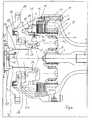
- the single FIGURE shows a section of a side of the drive axle with an axle tube 1, which is connectable to the vehicle, not shown, and which has a funnel-shaped extension 2, which is connected via connecting elements 3 with the housing 4.
- a drive shaft 5 drives an inner central gear 6 of a planetary gear 7 and can also be made in one piece with the drive shaft.
- the drive shaft is connected to a differential, not shown.
- a drive motor such as an electric motor or a hydraulic motor.
- the inner central wheel 6 is in operative connection with the planetary gear 8, wherein the planetary gear 8 on the outer central wheel 9, which is held against rotation, supported.
- the outer central wheel 9 by means of bolts 10 rotatably in the funnel-shaped extension 2 or the housing 4 is arranged.
- the outer central wheel 9 via a self-tapping toothing, a so-called “mouse teeth” rotatably in the funnel-shaped extension 2 or the housing 4 to hold.
- an arrangement of the outer central wheel as in EP 0 979 365 B1 is possible.
- the planetary gear 8 is mounted on the planet carrier 12 via the planetary bearing 11. At the radially outer region of the planet carrier 12, adjacent to the planetary gear 8, the inner rotating lamellae 13 of the multi-disc brake 14 are arranged rotationally fixed.
- the outer fins 15 are rotationally fixed in the housing 4 or the funnel-shaped extension 2 is arranged.
- the multi-disc brake 14 is disposed between the planetary gear 8 and the output flange 17. It is also possible to arrange the multi-disc brake 14 in the direction of a funnel-shaped enlargement. Between the multi-disc brake 14 and the output flange 17, a piston 18 is arranged, which actuates the multi-disc brake 14 in the closing direction when pressurized in the space 19.
- the piston 18 is pushed back by a return spring 20 when not in operation. It is possible, the return spring 20 to an automatic adjuster 21, which is arranged in the radially inner region of the piston 18.
- a clamping sleeve 22 is arranged in the piston 18, which acts on a disc 23 which is axially displaceable within a defined path and limited by two-sided stops of the axial path. Since the automatic adjusting device 21 is not fixed in the radial direction, it is also not necessary to fix the piston 18 in the radial direction.
- the piston 18 and the adjusting device is in the region of the first and second bearings.
- the planet carrier 12 has in the direction of the output flange 17 on a pin 24, on the surface of the inner ring 25 of the second bearing 26 is arranged.
- the pin 24 is rotatably connected via a non-rotatable connection 27, for example, a toothing or a meander-shaped configuration of the surface or a plurality of bolts with the output flange 17.
- This rotationally fixed connection 27 is arranged in a bore of the output flange 17.
- the output flange 17 is mounted in the housing 4 via a first bearing 28.
- the first bearing 28 is larger in its inner diameter than the second bearing 26 configured.
- a centering 29 is arranged Immediately adjacent to the inner ring 25, a centering 29 is arranged. About this centering 29 of the output flange 17 is centered on the pin 24. At the end 30 of the pin 24 facing away from the planetary gear 8 there is a bushing 31 which centers the output flange 17 on the pin 24. Thus, the output flange 17 is centered on the pin 24 via the bushing 31 and the centering 29, whereby the first bearing 28 and the second bearing 26 experience optimum operating conditions, because the output flange 17 can not tip against the planet carrier 12.
- the bushing 31 is cup-shaped and is clamped by means of connecting elements 32 in the direction of the pin 24, wherein the bush 31 presses the output flange 17 on the inner ring 25 via its axial abutment 33.
- a cover 36 with a seal 37 To protect the connecting elements 32 and for easier sealing of the output flange 17 is closed by a cover 36 with a seal 37.
- the output flange 17 is sealed off from the housing 4 via a radial shaft sealing ring 38, a so-called "cassette seal".
- the seal 38 is protected from contamination, the output flange 17 and the housing 4 are designed so that a labyrinth 39 is formed.
Landscapes
- Engineering & Computer Science (AREA)
- General Engineering & Computer Science (AREA)
- Mechanical Engineering (AREA)
- Chemical & Material Sciences (AREA)
- Combustion & Propulsion (AREA)
- Transportation (AREA)
- Retarders (AREA)
- General Details Of Gearings (AREA)
- Control Of Throttle Valves Provided In The Intake System Or In The Exhaust System (AREA)
- Automatic Cycles, And Cycles In General (AREA)
- Arrangement Of Transmissions (AREA)
- Braking Arrangements (AREA)
Claims (10)
- Système de transmission pour véhicules mobiles doté d'une boîte de vitesses épicycloïdale (7), dans laquelle un pignon central intérieur (6) forme le mécanisme d'entraînement (entrée), un pignon central extérieur (9) est maintenu solidaire en rotation et un arbre porte-satellites (12) - sur lequel est logé au moins un satellite (8) - forme la sortie, sachant que entre un carter (4) solidaire en rotation et une zone extérieure de l'arbre porte-satellites (12) sont disposés des disques d'un frein à disques multiples (14), sachant que l'arbre porte-satellites est lié, par l'intermédiaire d'un tourillon (24), celui-ci étant solidaire en rotation, à une bride de sortie (17) et qu'un premier palier (28) et un deuxième palier (26) sont disposés dans le carter (4) à une certaine distance l'un par rapport à l'autre, caractérisé en ce que la bride de sortie (17) est logée à l'aide du premier palier (28) et l'arbre porte-satellites est logé (12) à l'aide du deuxième palier (26) dans le carter (4), et que le deuxième palier (26) est fixé dans le sens axial à l'aide de la bride de sortie (17) et de l'arbre porte-satellites (12).
- Système de transmission pour véhicules mobiles selon la revendication 1, caractérisé en ce que la bride de sortie (17), tout en étant juxtaposée au deuxième palier (26), est centrée sur le tourillon (24) et en ce que dans la zone d'une extrémité (30) du tourillon (24), étant disposée sur le côté opposé à l'arbre porte-satellites, la bride de sortie (17) est centrée sur le tourillon (24) par l'intermédiaire d'une douille (31).
- Système de transmission pour véhicules mobiles selon la revendication 1, caractérisé en ce que la bride de sortie (17) comporte un alésage de logement du tourillon (24).
- Système de transmission pour véhicules mobiles selon la revendication 1, caractérisé en ce que le tourillon (24) est lié de façon solidaire en rotation et par l'intermédiaire d'une denture à la bride de sortie (17).
- Système de transmission pour véhicules mobiles selon la revendication 2, caractérisé en ce que la douille (31) est conçue en forme de pot et en ce qu'elle est liée d'une part dans le sens axial par l'intermédiaire d'éléments de fixation (32) au tourillon (24) et en ce que d'autre part elle adhère dans le sens axial à la bride de sortie (17).
- Système de transmission pour véhicules mobiles selon la revendication 5, caractérisé en ce que les éléments de fixation (32) sont disposés de manière à être dirigés vers une face extérieure du mécanisme d'entraînement (entrée).
- Système de transmission pour véhicules mobiles selon la revendication 1, caractérisé en ce que le diamètre intérieur du premier palier (28) est plus grand du diamètre intérieur du deuxième palier (26).
- Système de transmission pour véhicules mobiles selon la revendication 1, caractérisé en ce que dans la zone du premier palier (28) et du deuxième palier (26) est disposé un piston (18), à l'aide duquel le frein à disques multiples (14) peut être fermé.
- Système de transmission pour véhicules mobiles selon la revendication 8, caractérisé en ce que le piston (18) comporte un dispositif de rattrapage de jeu automatique (21).
- Système de transmission pour véhicules mobiles selon la revendication 1, caractérisé en ce que le frein (14) est disposé entre la bride de sortie (17) et le satellite (8).
Applications Claiming Priority (2)
| Application Number | Priority Date | Filing Date | Title |
|---|---|---|---|
| DE10326143A DE10326143A1 (de) | 2003-06-06 | 2003-06-06 | Antrieb für ein Mobil-Fahrzeug |
| PCT/EP2004/005854 WO2004108460A1 (fr) | 2003-06-06 | 2004-05-29 | Entrainement pour un engin mobile |
Publications (2)
| Publication Number | Publication Date |
|---|---|
| EP1631470A1 EP1631470A1 (fr) | 2006-03-08 |
| EP1631470B1 true EP1631470B1 (fr) | 2006-08-23 |
Family
ID=33482753
Family Applications (1)
| Application Number | Title | Priority Date | Filing Date |
|---|---|---|---|
| EP04739466A Expired - Lifetime EP1631470B1 (fr) | 2003-06-06 | 2004-05-29 | Entrainement pour un engin mobile |
Country Status (6)
| Country | Link |
|---|---|
| EP (1) | EP1631470B1 (fr) |
| JP (1) | JP2006527119A (fr) |
| KR (1) | KR20060025160A (fr) |
| AT (1) | ATE337198T1 (fr) |
| DE (2) | DE10326143A1 (fr) |
| WO (1) | WO2004108460A1 (fr) |
Cited By (2)
| Publication number | Priority date | Publication date | Assignee | Title |
|---|---|---|---|---|
| EP3144171A1 (fr) | 2015-09-18 | 2017-03-22 | Hitachi Construction Machinery Co., Ltd. | Dispositif d'essieu de déplacement |
| AU2016216638B2 (en) * | 2015-11-03 | 2017-12-21 | Arvinmeritor Technology, Llc | Axle assembly having a wet disc brake |
Families Citing this family (3)
| Publication number | Priority date | Publication date | Assignee | Title |
|---|---|---|---|---|
| CN104358804B (zh) * | 2014-10-29 | 2017-03-01 | 李开卫 | 多片湿式盘式制动器及其运行方法 |
| DE102017203708A1 (de) | 2017-03-07 | 2018-09-13 | Zf Friedrichshafen Ag | Hohlrad und mit dem Hohlrad drehfest verbindbares weiteres Element für ein Planetengetriebe, Planetengetriebe, Radkopf und Mobilbagger |
| DE102020103501A1 (de) | 2020-02-11 | 2021-08-12 | Audi Aktiengesellschaft | Demontagevorrichtung für eine Bauteilanordnung |
Family Cites Families (13)
| Publication number | Priority date | Publication date | Assignee | Title |
|---|---|---|---|---|
| DE2049630A1 (de) * | 1970-10-09 | 1972-04-13 | Klöckner-Humboldt-Deutz AG, 5000 Köln | Kraftfahrzeug mit einem Stirnradplanetengetriebe im Achsantrieb |
| FR2322757A1 (fr) * | 1975-09-02 | 1977-04-01 | Gkn Axles | Essieu moteur pour vehicules routiers |
| FR2350520A1 (fr) * | 1976-05-03 | 1977-12-02 | Etudes Rech Avancees | Ensemble de transmission entre un arbre moteur et un arbre mene, avec dispositif de freinage de l'arbre moteur |
| GB2075622B (en) * | 1980-05-03 | 1983-09-07 | Kgn Axles Ltd | Axle with multi-plate disc brake |
| JPS57104410A (en) * | 1980-12-22 | 1982-06-29 | Toyo Umpanki Co Ltd | Driving shaft device |
| US4442914A (en) * | 1982-09-13 | 1984-04-17 | Tadao Nishihara | Front wheel driving device of vehicle |
| DE3905292A1 (de) * | 1989-02-21 | 1990-08-23 | Linde Ag | Radantriebseinheit |
| DE4433100C2 (de) * | 1994-09-16 | 1998-10-15 | Zf Hurth Gotha Gmbh | Getriebe mit integrierter Bremse, insbesondere für eine Antriebseinheit eines Flurbeförderzeugs |
| US5645148A (en) * | 1995-06-23 | 1997-07-08 | Zf Padova S.P.A. | Transmission with built-in brake, particularly for vehicles |
| DE19718744C1 (de) * | 1997-05-02 | 1998-11-19 | Zahnradfabrik Friedrichshafen | Fahrzeuggetriebe mit integrierter Bremse |
| SE509788C2 (sv) * | 1997-07-18 | 1999-03-08 | Volvo Constr Equip Components | Planetväxel för ett fordonshjul |
| DE60123010T2 (de) * | 2001-02-23 | 2007-04-19 | Dana Italia S.P.A., Arco | Radnabe mit integriertem Planetengetriebe und Lamellenbremse |
| US6530859B2 (en) * | 2001-08-10 | 2003-03-11 | Caterpillar Inc | Drive assembly with mounting for rotating axle |
-
2003
- 2003-06-06 DE DE10326143A patent/DE10326143A1/de not_active Withdrawn
-
2004
- 2004-05-29 WO PCT/EP2004/005854 patent/WO2004108460A1/fr not_active Ceased
- 2004-05-29 EP EP04739466A patent/EP1631470B1/fr not_active Expired - Lifetime
- 2004-05-29 AT AT04739466T patent/ATE337198T1/de not_active IP Right Cessation
- 2004-05-29 JP JP2006508234A patent/JP2006527119A/ja not_active Withdrawn
- 2004-05-29 KR KR1020057023267A patent/KR20060025160A/ko not_active Ceased
- 2004-05-29 DE DE502004001288T patent/DE502004001288D1/de not_active Expired - Lifetime
Cited By (4)
| Publication number | Priority date | Publication date | Assignee | Title |
|---|---|---|---|---|
| EP3144171A1 (fr) | 2015-09-18 | 2017-03-22 | Hitachi Construction Machinery Co., Ltd. | Dispositif d'essieu de déplacement |
| US9903454B2 (en) | 2015-09-18 | 2018-02-27 | Hitachi Construction Machinery Co., Ltd. | Traveling axle device |
| AU2016216638B2 (en) * | 2015-11-03 | 2017-12-21 | Arvinmeritor Technology, Llc | Axle assembly having a wet disc brake |
| US10065455B2 (en) | 2015-11-03 | 2018-09-04 | Arvinmeritor Technology, Llc | Axle assembly having a wet disc brake |
Also Published As
| Publication number | Publication date |
|---|---|
| EP1631470A1 (fr) | 2006-03-08 |
| DE10326143A1 (de) | 2004-12-23 |
| ATE337198T1 (de) | 2006-09-15 |
| WO2004108460A1 (fr) | 2004-12-16 |
| KR20060025160A (ko) | 2006-03-20 |
| JP2006527119A (ja) | 2006-11-30 |
| DE502004001288D1 (de) | 2006-10-05 |
Similar Documents
| Publication | Publication Date | Title |
|---|---|---|
| EP0979365B2 (fr) | Transmission a frein integre et refroidisse | |
| EP1214214B1 (fr) | Systeme d'entrainement d'une roue de vehicule | |
| EP1167140B1 (fr) | Entrainement de roue à frein de service dynamique intégré | |
| EP1429054B1 (fr) | Etage de transmission planétaire | |
| EP1053147B1 (fr) | Moyeu de roue a engrenage planetaire integre et frein multidisque | |
| EP3225449B1 (fr) | Ensemble d'entraînement de moyeu de roue | |
| DE19805300B4 (de) | Nabenantrieb | |
| EP1285803A1 (fr) | Train de transmission pour une roue | |
| DE2831458A1 (de) | Radantrieb fuer hydrostatisch angetriebene arbeitsmaschinen, insbesondere fuer kettenfahrzeuge | |
| WO1988002450A1 (fr) | Frein a friction refroidi par liquide | |
| US6890282B2 (en) | Driveline for mobile vehicles | |
| DE10132319A1 (de) | Radnabenantrieb | |
| DE4228815C2 (de) | Zweistufiges Planetengetriebe | |
| DE4206102C2 (de) | Hydromechanisches Getriebe | |
| DE19741207A1 (de) | Antriebsachse | |
| EP1631470A1 (fr) | Entrainement pour un engin mobile | |
| EP2100038B1 (fr) | Moteur à piston radial hydraulique | |
| DE60106994T2 (de) | Radnabe für Kraftfahrzeuge | |
| EP1631751B1 (fr) | Dispositif d'ajustement d'usure pour transmissions de vehicules mobiles | |
| DE10258913A1 (de) | Radantrieb mit einem Planetengetriebe und einer Bremse | |
| DE102023123855A1 (de) | Scheibenbremsvorrichtung und Verfahren zum Zusammenbau derselben | |
| EP3837132B1 (fr) | Train d'engrenages, notamment pour une unité de propulsion de roue indépendante | |
| EP1130289A2 (fr) | Essieu de véhicule | |
| EP1133404A1 (fr) | Entrainement de roue orientable | |
| DE10147853A1 (de) | Getriebe |
Legal Events
| Date | Code | Title | Description |
|---|---|---|---|
| PUAI | Public reference made under article 153(3) epc to a published international application that has entered the european phase |
Free format text: ORIGINAL CODE: 0009012 |
|
| 17P | Request for examination filed |
Effective date: 20051001 |
|
| AK | Designated contracting states |
Kind code of ref document: A1 Designated state(s): AT BE BG CH CY CZ DE DK EE ES FI FR GB GR HU IE IT LI LU MC NL PL PT RO SE SI SK TR |
|
| GRAP | Despatch of communication of intention to grant a patent |
Free format text: ORIGINAL CODE: EPIDOSNIGR1 |
|
| GRAS | Grant fee paid |
Free format text: ORIGINAL CODE: EPIDOSNIGR3 |
|
| GRAA | (expected) grant |
Free format text: ORIGINAL CODE: 0009210 |
|
| AK | Designated contracting states |
Kind code of ref document: B1 Designated state(s): AT BE BG CH CY CZ DE DK EE ES FI FR GB GR HU IE IT LI LU MC NL PL PT RO SE SI SK TR |
|
| DAX | Request for extension of the european patent (deleted) | ||
| PG25 | Lapsed in a contracting state [announced via postgrant information from national office to epo] |
Ref country code: CZ Free format text: LAPSE BECAUSE OF FAILURE TO SUBMIT A TRANSLATION OF THE DESCRIPTION OR TO PAY THE FEE WITHIN THE PRESCRIBED TIME-LIMIT Effective date: 20060823 Ref country code: FI Free format text: LAPSE BECAUSE OF FAILURE TO SUBMIT A TRANSLATION OF THE DESCRIPTION OR TO PAY THE FEE WITHIN THE PRESCRIBED TIME-LIMIT Effective date: 20060823 Ref country code: IE Free format text: LAPSE BECAUSE OF FAILURE TO SUBMIT A TRANSLATION OF THE DESCRIPTION OR TO PAY THE FEE WITHIN THE PRESCRIBED TIME-LIMIT Effective date: 20060823 Ref country code: NL Free format text: LAPSE BECAUSE OF FAILURE TO SUBMIT A TRANSLATION OF THE DESCRIPTION OR TO PAY THE FEE WITHIN THE PRESCRIBED TIME-LIMIT Effective date: 20060823 Ref country code: PL Free format text: LAPSE BECAUSE OF FAILURE TO SUBMIT A TRANSLATION OF THE DESCRIPTION OR TO PAY THE FEE WITHIN THE PRESCRIBED TIME-LIMIT Effective date: 20060823 Ref country code: RO Free format text: LAPSE BECAUSE OF FAILURE TO SUBMIT A TRANSLATION OF THE DESCRIPTION OR TO PAY THE FEE WITHIN THE PRESCRIBED TIME-LIMIT Effective date: 20060823 Ref country code: SI Free format text: LAPSE BECAUSE OF FAILURE TO SUBMIT A TRANSLATION OF THE DESCRIPTION OR TO PAY THE FEE WITHIN THE PRESCRIBED TIME-LIMIT Effective date: 20060823 Ref country code: SK Free format text: LAPSE BECAUSE OF FAILURE TO SUBMIT A TRANSLATION OF THE DESCRIPTION OR TO PAY THE FEE WITHIN THE PRESCRIBED TIME-LIMIT Effective date: 20060823 |
|
| REG | Reference to a national code |
Ref country code: GB Ref legal event code: FG4D Free format text: NOT ENGLISH |
|
| REG | Reference to a national code |
Ref country code: CH Ref legal event code: EP |
|
| REG | Reference to a national code |
Ref country code: IE Ref legal event code: FG4D Free format text: LANGUAGE OF EP DOCUMENT: GERMAN |
|
| REF | Corresponds to: |
Ref document number: 502004001288 Country of ref document: DE Date of ref document: 20061005 Kind code of ref document: P |
|
| GBT | Gb: translation of ep patent filed (gb section 77(6)(a)/1977) |
Effective date: 20061101 |
|
| PG25 | Lapsed in a contracting state [announced via postgrant information from national office to epo] |
Ref country code: DK Free format text: LAPSE BECAUSE OF FAILURE TO SUBMIT A TRANSLATION OF THE DESCRIPTION OR TO PAY THE FEE WITHIN THE PRESCRIBED TIME-LIMIT Effective date: 20061123 Ref country code: BG Free format text: LAPSE BECAUSE OF FAILURE TO SUBMIT A TRANSLATION OF THE DESCRIPTION OR TO PAY THE FEE WITHIN THE PRESCRIBED TIME-LIMIT Effective date: 20061123 |
|
| REG | Reference to a national code |
Ref country code: SE Ref legal event code: TRGR |
|
| PG25 | Lapsed in a contracting state [announced via postgrant information from national office to epo] |
Ref country code: ES Free format text: LAPSE BECAUSE OF FAILURE TO SUBMIT A TRANSLATION OF THE DESCRIPTION OR TO PAY THE FEE WITHIN THE PRESCRIBED TIME-LIMIT Effective date: 20061204 |
|
| PG25 | Lapsed in a contracting state [announced via postgrant information from national office to epo] |
Ref country code: PT Free format text: LAPSE BECAUSE OF FAILURE TO SUBMIT A TRANSLATION OF THE DESCRIPTION OR TO PAY THE FEE WITHIN THE PRESCRIBED TIME-LIMIT Effective date: 20070124 |
|
| REG | Reference to a national code |
Ref country code: HU Ref legal event code: AG4A Ref document number: E000941 Country of ref document: HU |
|
| NLV1 | Nl: lapsed or annulled due to failure to fulfill the requirements of art. 29p and 29m of the patents act | ||
| REG | Reference to a national code |
Ref country code: IE Ref legal event code: FD4D |
|
| EN | Fr: translation not filed | ||
| PLBE | No opposition filed within time limit |
Free format text: ORIGINAL CODE: 0009261 |
|
| STAA | Information on the status of an ep patent application or granted ep patent |
Free format text: STATUS: NO OPPOSITION FILED WITHIN TIME LIMIT |
|
| 26N | No opposition filed |
Effective date: 20070524 |
|
| BERE | Be: lapsed |
Owner name: ZF FRIEDRICHSHAFEN A.G. Effective date: 20070531 |
|
| PG25 | Lapsed in a contracting state [announced via postgrant information from national office to epo] |
Ref country code: HU Free format text: LAPSE BECAUSE OF NON-PAYMENT OF DUE FEES Effective date: 20070530 Ref country code: MC Free format text: LAPSE BECAUSE OF NON-PAYMENT OF DUE FEES Effective date: 20070531 |
|
| PG25 | Lapsed in a contracting state [announced via postgrant information from national office to epo] |
Ref country code: BE Free format text: LAPSE BECAUSE OF NON-PAYMENT OF DUE FEES Effective date: 20070531 |
|
| PG25 | Lapsed in a contracting state [announced via postgrant information from national office to epo] |
Ref country code: GR Free format text: LAPSE BECAUSE OF FAILURE TO SUBMIT A TRANSLATION OF THE DESCRIPTION OR TO PAY THE FEE WITHIN THE PRESCRIBED TIME-LIMIT Effective date: 20061124 Ref country code: FR Free format text: LAPSE BECAUSE OF FAILURE TO SUBMIT A TRANSLATION OF THE DESCRIPTION OR TO PAY THE FEE WITHIN THE PRESCRIBED TIME-LIMIT Effective date: 20070511 |
|
| PG25 | Lapsed in a contracting state [announced via postgrant information from national office to epo] |
Ref country code: EE Free format text: LAPSE BECAUSE OF FAILURE TO SUBMIT A TRANSLATION OF THE DESCRIPTION OR TO PAY THE FEE WITHIN THE PRESCRIBED TIME-LIMIT Effective date: 20060823 |
|
| PG25 | Lapsed in a contracting state [announced via postgrant information from national office to epo] |
Ref country code: AT Free format text: LAPSE BECAUSE OF NON-PAYMENT OF DUE FEES Effective date: 20070529 |
|
| PG25 | Lapsed in a contracting state [announced via postgrant information from national office to epo] |
Ref country code: FR Free format text: LAPSE BECAUSE OF FAILURE TO SUBMIT A TRANSLATION OF THE DESCRIPTION OR TO PAY THE FEE WITHIN THE PRESCRIBED TIME-LIMIT Effective date: 20060823 |
|
| REG | Reference to a national code |
Ref country code: CH Ref legal event code: PL |
|
| GBPC | Gb: european patent ceased through non-payment of renewal fee |
Effective date: 20080529 |
|
| PG25 | Lapsed in a contracting state [announced via postgrant information from national office to epo] |
Ref country code: LI Free format text: LAPSE BECAUSE OF NON-PAYMENT OF DUE FEES Effective date: 20080531 Ref country code: CH Free format text: LAPSE BECAUSE OF NON-PAYMENT OF DUE FEES Effective date: 20080531 |
|
| PG25 | Lapsed in a contracting state [announced via postgrant information from national office to epo] |
Ref country code: GB Free format text: LAPSE BECAUSE OF NON-PAYMENT OF DUE FEES Effective date: 20080529 |
|
| PG25 | Lapsed in a contracting state [announced via postgrant information from national office to epo] |
Ref country code: LU Free format text: LAPSE BECAUSE OF NON-PAYMENT OF DUE FEES Effective date: 20070529 Ref country code: CY Free format text: LAPSE BECAUSE OF FAILURE TO SUBMIT A TRANSLATION OF THE DESCRIPTION OR TO PAY THE FEE WITHIN THE PRESCRIBED TIME-LIMIT Effective date: 20060823 |
|
| PG25 | Lapsed in a contracting state [announced via postgrant information from national office to epo] |
Ref country code: TR Free format text: LAPSE BECAUSE OF FAILURE TO SUBMIT A TRANSLATION OF THE DESCRIPTION OR TO PAY THE FEE WITHIN THE PRESCRIBED TIME-LIMIT Effective date: 20060823 |
|
| PG25 | Lapsed in a contracting state [announced via postgrant information from national office to epo] |
Ref country code: IT Free format text: LAPSE BECAUSE OF NON-PAYMENT OF DUE FEES Effective date: 20080529 |
|
| PGFP | Annual fee paid to national office [announced via postgrant information from national office to epo] |
Ref country code: IT Payment date: 20070531 Year of fee payment: 4 |
|
| PGFP | Annual fee paid to national office [announced via postgrant information from national office to epo] |
Ref country code: SE Payment date: 20150512 Year of fee payment: 12 |
|
| PG25 | Lapsed in a contracting state [announced via postgrant information from national office to epo] |
Ref country code: SE Free format text: LAPSE BECAUSE OF NON-PAYMENT OF DUE FEES Effective date: 20160530 |
|
| P01 | Opt-out of the competence of the unified patent court (upc) registered |
Effective date: 20230528 |
|
| PGFP | Annual fee paid to national office [announced via postgrant information from national office to epo] |
Ref country code: DE Payment date: 20230404 Year of fee payment: 20 |
|
| REG | Reference to a national code |
Ref country code: DE Ref legal event code: R071 Ref document number: 502004001288 Country of ref document: DE |