EP1630948A1 - Leistungsregelung für Drehfeldmaschinen - Google Patents
Leistungsregelung für Drehfeldmaschinen Download PDFInfo
- Publication number
- EP1630948A1 EP1630948A1 EP04020382A EP04020382A EP1630948A1 EP 1630948 A1 EP1630948 A1 EP 1630948A1 EP 04020382 A EP04020382 A EP 04020382A EP 04020382 A EP04020382 A EP 04020382A EP 1630948 A1 EP1630948 A1 EP 1630948A1
- Authority
- EP
- European Patent Office
- Prior art keywords
- stator
- induction machine
- rotor
- voltage
- current
- Prior art date
- Legal status (The legal status is an assumption and is not a legal conclusion. Google has not performed a legal analysis and makes no representation as to the accuracy of the status listed.)
- Granted
Links
- 230000033228 biological regulation Effects 0.000 title claims description 12
- 230000006698 induction Effects 0.000 claims abstract description 103
- 238000000034 method Methods 0.000 claims abstract description 36
- 230000006870 function Effects 0.000 claims abstract description 16
- 238000004590 computer program Methods 0.000 claims abstract description 12
- 230000001105 regulatory effect Effects 0.000 claims abstract description 9
- 230000004907 flux Effects 0.000 claims description 45
- 238000004364 calculation method Methods 0.000 claims description 18
- 230000009466 transformation Effects 0.000 claims description 13
- 230000001276 controlling effect Effects 0.000 claims description 11
- 230000001131 transforming effect Effects 0.000 claims description 4
- 238000004804 winding Methods 0.000 claims description 4
- 230000005284 excitation Effects 0.000 claims description 2
- 238000012545 processing Methods 0.000 description 11
- 239000013598 vector Substances 0.000 description 9
- 230000001360 synchronised effect Effects 0.000 description 8
- 238000005259 measurement Methods 0.000 description 6
- 230000015572 biosynthetic process Effects 0.000 description 4
- 238000013461 design Methods 0.000 description 4
- 239000011159 matrix material Substances 0.000 description 4
- 238000003786 synthesis reaction Methods 0.000 description 4
- 241000555745 Sciuridae Species 0.000 description 3
- 230000004044 response Effects 0.000 description 3
- 230000008901 benefit Effects 0.000 description 2
- 238000004422 calculation algorithm Methods 0.000 description 2
- 238000006243 chemical reaction Methods 0.000 description 2
- 238000005094 computer simulation Methods 0.000 description 2
- 238000009795 derivation Methods 0.000 description 2
- 230000000717 retained effect Effects 0.000 description 2
- 230000006641 stabilisation Effects 0.000 description 2
- 238000011105 stabilization Methods 0.000 description 2
- 238000013459 approach Methods 0.000 description 1
- 239000003990 capacitor Substances 0.000 description 1
- 230000008034 disappearance Effects 0.000 description 1
- 230000000694 effects Effects 0.000 description 1
- 238000004146 energy storage Methods 0.000 description 1
- 230000002349 favourable effect Effects 0.000 description 1
- 238000012423 maintenance Methods 0.000 description 1
- 238000013178 mathematical model Methods 0.000 description 1
- 230000008569 process Effects 0.000 description 1
- 230000001172 regenerating effect Effects 0.000 description 1
Images


Classifications
-
- H—ELECTRICITY
- H02—GENERATION; CONVERSION OR DISTRIBUTION OF ELECTRIC POWER
- H02P—CONTROL OR REGULATION OF ELECTRIC MOTORS, ELECTRIC GENERATORS OR DYNAMO-ELECTRIC CONVERTERS; CONTROLLING TRANSFORMERS, REACTORS OR CHOKE COILS
- H02P9/00—Arrangements for controlling electric generators for the purpose of obtaining a desired output
- H02P9/007—Control circuits for doubly fed generators
-
- H—ELECTRICITY
- H02—GENERATION; CONVERSION OR DISTRIBUTION OF ELECTRIC POWER
- H02J—CIRCUIT ARRANGEMENTS OR SYSTEMS FOR SUPPLYING OR DISTRIBUTING ELECTRIC POWER; SYSTEMS FOR STORING ELECTRIC ENERGY
- H02J3/00—Circuit arrangements for ac mains or ac distribution networks
- H02J3/18—Arrangements for adjusting, eliminating or compensating reactive power in networks
- H02J3/1885—Arrangements for adjusting, eliminating or compensating reactive power in networks using rotating means, e.g. synchronous generators
-
- H—ELECTRICITY
- H02—GENERATION; CONVERSION OR DISTRIBUTION OF ELECTRIC POWER
- H02P—CONTROL OR REGULATION OF ELECTRIC MOTORS, ELECTRIC GENERATORS OR DYNAMO-ELECTRIC CONVERTERS; CONTROLLING TRANSFORMERS, REACTORS OR CHOKE COILS
- H02P23/00—Arrangements or methods for the control of AC motors characterised by a control method other than vector control
- H02P23/06—Controlling the motor in four quadrants
- H02P23/07—Polyphase or monophase asynchronous induction motors
-
- Y—GENERAL TAGGING OF NEW TECHNOLOGICAL DEVELOPMENTS; GENERAL TAGGING OF CROSS-SECTIONAL TECHNOLOGIES SPANNING OVER SEVERAL SECTIONS OF THE IPC; TECHNICAL SUBJECTS COVERED BY FORMER USPC CROSS-REFERENCE ART COLLECTIONS [XRACs] AND DIGESTS
- Y02—TECHNOLOGIES OR APPLICATIONS FOR MITIGATION OR ADAPTATION AGAINST CLIMATE CHANGE
- Y02E—REDUCTION OF GREENHOUSE GAS [GHG] EMISSIONS, RELATED TO ENERGY GENERATION, TRANSMISSION OR DISTRIBUTION
- Y02E40/00—Technologies for an efficient electrical power generation, transmission or distribution
- Y02E40/30—Reactive power compensation
Definitions
- the present invention relates to the regulation of the output and recorded by a rotating field machine active and reactive power.
- Rotary field machines such as the synchronous machine and the asynchronous machine with cage or slip ring rotor are used in a variety of technical applications both in motor and generator operation.
- asynchronous and synchronous generators used in plants for the decentralized generation of electrical energy, e.g. Wind turbines, wave generators, flywheel energy storage and combined heat and power plants.
- synchronous generators and asynchronous generators with squirrel-cage rotors are in principle capable of delivering the generated electrical energy with constant voltage and frequency directly to the three-phase system.
- the advantages of such systems are simple and robust design, low maintenance and high reliability.
- Speed-variable systems such as the asynchronous machine with slip ring rotor, are able to deliver an adapted electrical power at variable speed of the generator.
- the stator of the machine is connected to the grid and the amplitude and frequency of its voltage are given by the grid.
- the rotor is a variable voltage with variable amplitude and frequency impressed by a pulse inverter, which is part of an inverter. By changing this three-phase system voltage with variable slip frequency applied to the rotor, it is possible to set all possible operating states (eg undersynchronous or oversynchronous as well as motor and regenerative operation).
- the field-oriented control is usually used, as shown for example in EP 0 043 973 A1.
- the goal of the field-oriented control is to realize the decoupling of field- and moment-forming components of the current, i. that the torque and the magnetizing current (or the rotor flux) are independently adjustable. This behavior arises in asynchronous machines with slip ring rotor when the rotor current is oriented to the rotor flux space pointer.
- the control takes place here in a rotating field coordinate system, wherein for the coordinate transformation of the rotor position angle and the position of the stator voltage must be known.
- the active and reactive power of the induction machine can be controlled only indirectly in this process, it is also a subordinate to the power control loop current control loop in the form of a cascade control required.
- the mechanical subsystem is controlled by a PI controller which compensates for the setpoint variations of the state variable resulting as a cross product (ie vector product) of stator flux and rotor current, while controlling the electromagnetic subsystem via a PI controller, the setpoint variance of the state variable , which results as a scalar product of stator flux and rotor current, corrects.
- a control circuit for controlling the active and reactive power it is necessary to superimpose a control circuit for controlling the active and reactive power in the form of a cascade control the control circuits for controlling the mechanical and electromagnetic subsystem.
- the output of the active power controller, the target size for the mechanical control loop and the output of the reactive power controller is the target size for the electromagnetic control loop.
- the control In Krzeminski power control, the control is no longer carried out in a rotating field coordinate system, but can be carried out in a fixed winding coordinate system, ie either in a stator-fixed or rotor-fixed coordinate system.
- a fixed winding coordinate system ie either in a stator-fixed or rotor-fixed coordinate system.
- the Control in winding-fixed coordinate systems possible because the products contain full information about the mutual position of the stator flux vector and rotor current vector.
- the non-linear feedback allows a linearization and thus a simplification of the mechanical and electromagnetic control loop.
- Krzeminski's benefit scheme has some disadvantages.
- the parameters of the control depend strongly on the operating point used (for example, the speed), so that the controllers used in the power control loop and the subordinate mechanical and electromagnetic control circuits must be redesigned at different operating points.
- the slip range of the scheme is limited.
- a method for controlling the delivered and recorded by a rotating field machine active and reactive power in a winding fixed coordinate system, wherein a first controller output variable is generated in response to a setpoint deviation of the active power with a first controller and in response to a setpoint deviation of the reactive power a second controller output is generated to a second controller, and wherein the first and second controller output are supplied with respective feedback quantities,
- the Functions of at least one time-variable system size of the induction machine are characterized in that a voltage or a current of the induction machine is determined as the manipulated variable at least from the first and second controller output variables acted upon by the feedback variables without further regulation.
- the induction machine can be an asynchronous machine with squirrel cage or slip ring rotor or a synchronous machine, which can each work as a motor or generator. In the case of the asynchronous machine, both under- and over-synchronous operation is possible.
- a setpoint value for the active power and a setpoint value for the reactive power are specified, and a possible setpoint deviation is determined by comparison with the measured active and reactive powers (actual powers).
- a voltage or a current of the induction machine is changed as a manipulated variable of the control until the setpoint deviations disappear or at least fall below a predetermined threshold. If the induction machine is a double-fed asynchronous machine, the manipulated variable can be, for example, the voltage impressed into the rotor.
- the regulation takes place in a winding-fixed coordinate system (stator fixed or rotorfest), which can be achieved for example by a suitable choice of the feedback variables.
- field-oriented regulation therefore requires no information about the space-phasing of currents and voltages of the induction machine (eg of the stator voltage vector) relative to a specific coordinate system.
- only one controller is used for respectively controlling the target value deviation of the active power and the target value deviation of the reactive power.
- This can be a linear controller, such as a proportional controller (P controller), a proportional-integral controller (PI controller) with a linear integrator algorithm, a proportional-derivative controller (PD controller) or a proportional controller Integral differential controller (PID controller), or else a non-linear controller, such as a PI controller with non-linear integrator algorithm act; however, all other types of controllers can be used.
- P controller proportional controller
- PI controller proportional-integral controller
- PD controller proportional-derivative controller
- PID controller proportional controller Integral differential controller
- This simple structure is achieved by directly selecting the active and reactive power as state variables on which the control is based. This makes it possible to dispense with further subordinate control loops.
- the first and second controller output variables are subjected to feedback variables which are selected such that the state variables are at least partially decoupled and a stabilization
- the basis for the solution according to the invention is the approach of a multi-scalar control, in which, in contrast to the prior art, however, the active power and the reactive power are defined directly as state variables. This leads to the omission of lower-level control loops in the synthesis of the control.
- the feedback variables are determined as functions from at least one time-variable system variable of the induction machine, wherein said time-variable system variables are represented for example by voltages, currents or fluxes in the stator and / or rotor of the induction machine or the rotor speed.
- the feedback variables and the parameters of the controllers are advantageously matched to one another and to the system to be controlled.
- the regulators (46-1, 46-2) are linear regulators.
- the feedback quantities that are applied to the first and second controller outputs of the two controllers can be selected so that the choice the active and reactive power is linearized as a state variable per se nonlinear system.
- the original state equations of the induction machine are reshaped so that the equations of state of the active and reactive power are linearized.
- the linearized equations of state can then be represented as linear terms in the state matrix describing the linking of state variables.
- the linearized state equations for the active and reactive power respectively correspond, for example, to a first-order low-pass system.
- the time constants of these low-pass systems depend on the state matrix of the transformed overall system.
- linear controller can be used, whereby a cost-effective, but above all, a simple and widely stable control of the active and reactive power can be accomplished.
- the regulators are PI regulators.
- the PI controller forces the rapid disappearance of a stationary control deviation. Both ideal and non-ideal PI controllers can be used.
- the time constants of the PI controllers are advantageously selected taking into account the influence of the feedback variables on the overall system.
- a rotor voltage of the induction machine is determined as a manipulated variable.
- the induction machine can then be a double-fed asynchronous machine, for example.
- a stator voltage of the induction machine is determined as the manipulated variable.
- the induction machine can then be, for example, an asynchronous machine with squirrel cage.
- an excitation current of the induction machine is determined as a manipulated variable.
- the induction machine can then be, for example, a separately excited synchronous machine.
- the Ohmic resistance of the stator of the induction machine is neglected in the calculation of the feedback variables. This greatly simplifies the calculation of the feedback quantities. Any inaccuracies of the system modeling by neglecting the stator resistance are advantageously compensated by the control loop.
- a stationary state is assumed in the calculation of the feedback variables. This measure also greatly simplifies the calculation of the feedback variables. Any inaccuracies of the system modeling by the assumption of a steady state are advantageously compensated by the control loop.
- the active and reactive power of the stator of the induction machine is controlled.
- the active and reactive power of the network to which the induction machine is connected regulated.
- the first regulator output quantity is subjected to a feedback variable which corresponds to the cross product of rotor voltage and stator flux of the induction machine
- the second regulator output variable is subjected to a feedback variable which corresponds to the scalar product of rotor voltage and stator flux.
- the cross and scalar products need not necessarily be calculated directly from the rotor voltage and the stator flux, it is also an indirect calculation of the feedback variables on functions of the system sizes of the induction machine possible, which correspond to the cross and scalar products.
- the choice of the feedback quantities according to this preferred embodiment of the present invention is particularly suitable for a double-fed asynchronous machine in which the rotor voltage is used as a control manipulated variable.
- the feedback quantities are functions of at least the stator voltage, the stator flux, the rotor current and the rotor speed.
- the feedback quantities can generally not be calculated directly from the cross and scalar products of rotor voltage and stator flux, since the rotor voltage serves as a manipulated variable. From the state equations describing the state variables of the induction machine, however, the feedback quantities can be derived as functions from at least the stator voltage, the stator flux, the rotor current and the rotor speed. These functions may additionally depend on the inductances of the induction machine and the stator resistance. The dependence of the feedback variables of stator voltage, stator flux, rotor current and rotor speed results, for example, in the case of the double-fed asynchronous machine when using the rotor voltage as a control variable of the control.
- the rotor voltage of the Rotary field machine determined as a control variable without further control from the acted upon by the feedback variables first and second controller output variables and the stator flux.
- At least the stator voltage and the rotor current of the induction machine are measured.
- Such a procedure is particularly advantageous for a double-fed asynchronous machine.
- the measurement can be done, for example, in natural three-phase coordinates and the measured variables can then be transformed into a two-phase coordinate system.
- the stator current of the induction machine is measured. If there is no position sensor for measuring the rotor attitude angle and the rotor speed, the stator current measurement may be required to allow calculation of rotor attitude angle and rotor speed.
- the rotor speed of the induction machine is measured or determined from the stator voltage, the stator current and the rotor current of the induction machine.
- the measurement of the rotor speed can be done for example via a position sensor.
- the rotor position angle of Rotary field machine measured or determined from the stator voltage, the stator current and the rotor current of the induction machine.
- the measurement of the rotor position angle can be done for example via a position sensor.
- the stator flux of the induction machine is calculated from the stator voltage and the angular frequency of the stator voltage of the induction machine.
- voltages and currents of the induction machine are each measured and then transformed into a two-phase coordinate system, and the manipulated variable is determined in a two-phase coordinate system and then transformed into a three-phase coordinate system.
- the voltages and currents of the induction machine are measured as natural three-phase quantities.
- the induction machine is a double-fed asynchronous machine whose stator is connected directly to a network, and whose rotor is connected to a converter.
- the inverter can contain two pulse inverters and one intermediate circuit, one of the pulse inverters can be connected to the rotor, and the other pulse inverter can be connected to the network.
- the induction machine can also be a squirrel-cage induction machine or a synchronous machine.
- a computer program is also proposed with instructions whose execution causes a processor to perform the control method described above.
- the presented control method is very well suited for implementation on a processor, which receives, for example, the setpoint deviations and the feedback variables as input variables and outputs the manipulated variable as the output variable.
- the calculation of the feedback variables can also be implemented within the program if the processor is supplied with the required measured values of the currents, voltages, fluxes and angular velocity of the induction machine.
- the computer program can for example be loaded into the main memory of the processor when the rotary field machine is started up and then executed. A subsequent adjustment of the parameters of the controller or optionally the feedback variables is advantageously possible.
- a computer program product which contains a computer program with instructions whose execution causes a processor to carry out the control method described above.
- the computer program product may include a removable medium, such as a removable medium. a memory card, a floppy disk or a CD, on which a computer program with the instructions for executing the control method is stored.
- a device for controlling the output and recorded by a rotary field machine active and reactive power in a winding-fixed coordinate system, with a first controller for generating a first controller output variable at nominal value deviations of the active power, with a second controller for generating a second controller output variable at target value deviations of the reactive power, and with means for acting on the first and second controller output variable with respective feedback variables, which are functions of at least one time-variable System size of the induction machine revealed, characterized in that the device comprises means for determining a voltage or a current of the induction machine as a manipulated variable from at least the acted upon by the feedback variables first and second controller output variables without further regulation.
- the device according to the present invention can be, for example, a modular controller unit with interfaces for inputting setpoint deviations and measured variables and for outputting the manipulated variables.
- the device can be firmly integrated into the induction machine. Due to the suitable selection of the feedback variables, the device requires only one controller for regulating the active power and one controller for controlling the reactive power, the controller output variables being combined with the corresponding feedback variables for determining the manipulated variable of the controller after being acted upon.
- the regulators are linear regulators.
- the regulators are PI regulators.
- the means for determining a voltage or a current of the induction machine determines a rotor voltage as a manipulated variable.
- the means for determining a voltage or a current of the induction machine determines a stator voltage as a manipulated variable.
- the means for determining a voltage or a current of the induction machine determines an exciting current as a manipulated variable.
- the active and reactive power of the stator of the induction machine is controlled.
- the active and reactive power of the network to which the induction machine is connected regulated.
- the regulator output of the first regulator is applied with a feedback amount corresponding to the cross product of rotor voltage and stator flux of the induction machine
- the regulator output of the second regulator is applied with a feedback amount corresponding to the dot product of rotor voltage and stator flux
- the feedback quantities are functions of the stator voltage, the stator flux, the rotor current and the angular velocity of the rotor.
- the rotor voltage of the induction machine is determined as a control variable from the acted upon by the feedback variables first and second controller output variables and the stator without further regulation.
- the device comprises means for measuring the stator voltage and the rotor current of the induction machine.
- the device comprises means for measuring the stator current.
- the device comprises means for measuring the rotor speed of the induction machine or for their determination from the stator voltage, the stator current and the rotor current of the induction machine.
- the device comprises means for measuring the rotor position angle of the induction machine or for its determination from the stator voltage, the stator current and the rotor current of the induction machine.
- the device comprises means for measuring the voltages and currents of the induction machine and for their transformation into a two-phase coordinate system, and means for transforming the control variable determined in a two-phase coordinate system into a three-phase coordinate system.
- the induction machine is a double-fed asynchronous machine whose stator is connected directly to a network, and whose rotor is connected to a converter.
- a rotating field machine is also proposed with a device for controlling the output from the induction machine or recorded active and reactive power in a winding-fixed coordinate system according to the device features already described above.
- the induction machine may be both an asynchronous machine with cage or slip ring rotor and a synchronous machine.
- the present invention relates to the control of the active and reactive power of induction machines. This control is explained below using the example of a double-fed asynchronous machine with inverter in the rotor circuit. However, the control according to the invention is equally suitable for other induction machines, in particular for asynchronous machines with squirrel cage and full converter in the stator circuit and synchronous machines.
- Fig. 1 shows such an asynchronous machine 1, which consists of a stator (stator) 10 and a rotor (rotor) 11.
- the rotor is connected directly or via a gearbox to a drive shaft and can thus either pick up mechanical power (generator operation) or release it (engine operation).
- the stator 10 of the asynchronous machine 1 according to FIG. 1 is connected directly to a three-phase system 3, while the rotor 11 is connected via an inverter 2 to the three-phase system 3 connected.
- the converter 2 consists of a line-side pulse inverter 22 and a machine-side pulse inverter 20.
- a capacitor 21 is provided in the intermediate circuit, so that the slip powers can be transmitted in both directions via the inverter 2. Due to the fixed connection of the stator 10 with the three-phase network 3, the stator voltage is generally given by the network (according to amplitude and frequency), an exception here form the island grids.
- the rotor 11 is impressed with a variable voltage variable frequency by the pulse inverter 20, whereby various operating conditions (under-synchronous / over-synchronous operation and motor / generator operation) can be set. Accordingly, the recording or output of active power and reactive power of the asynchronous machine 1 can be controlled via the impressing of the rotor voltage.
- ⁇ r and ⁇ s are the stator and rotor flux vectors
- i s and i r are the stator and rotor current vectors
- u s and u r the stator and rotor voltage vectors
- R s and R r are the stator and rotor winding resistances
- m 0 is the torque
- J is the moment of inertia
- ⁇ r is the rotor speed
- ⁇ a is the rotational speed of the reference coordinate system
- ⁇ is the relative time.
- Bold letters refer to vectorial quantities here and below, while italics indicate scalar quantities here and in the following.
- w ⁇ L s L r - L m 2 ,
- the first index indicates the location (r: rotor, s: stator, respectively)
- the second index indicates the respective component in a two-phase coordinate system ( ⁇ , ⁇ )
- third index denotes the reference system used (S: Statorwicklungsfest, R: Rotorwickungsfest).
- Q s - 1 L s ( u s ⁇ S ⁇ s ⁇ S + u s ⁇ S ⁇ s s )
- ⁇ s S 2 ⁇ s ⁇ S 2 + ⁇ s ⁇ S 2 ,
- the differential equations (22) and (23) are not suitable for the controller design due to the strong nonlinearity. Therefore, the present invention contemplates transforming the system of equations of state so that the real and reactive powers form a linear element in the system matrix.
- the system state representation the system may be given a highly nonlinear character. This non-linear behavior is in turn compensated by non-linear feedback elements.
- the newly defined system should receive first-order low-pass behavior for each of the active power and the reactive power. The time constants of these low passes depend on the state matrix of the newly defined system.
- two linear regulators e.g. two PI controllers are used.
- v 1 from equation (25) corresponds to the cross product of rotor voltage and stator flux
- v 2 from equation (26) to the scalar product of rotor voltage and stator flux.
- the choice of the state variables and these variables v 1 and v 2 makes it possible to dispense with the information about the space vector position in the control according to the invention, thereby enabling control in a winding-fixed coordinate system and allowing a simple controller synthesis despite non-linearity.
- the state of the asynchronous machine 1 depends on the mutual position of the space pointer, which have been chosen to describe the dynamics.
- the relationships between space pointers can also be described without separate angle information by means of cross and scalar products.
- the state vectors according to the present invention were therefore chosen so that a description by cross and scalar products is possible.
- Equations (27) to (30) are used according to the present invention directly for the synthesis of the control.
- Fig. 2 shows a schematic representation of this scheme. Shown again are the double-fed asynchronous machine 1 with stator 10 and rotor 11, the feeding network 3 and the inverter 2.
- stator current i sS can be measured and converted by means of a transformation unit 40-4 into a two-phase, stator-fixed coordinate system in order to enable a calculation of the rotor speed ⁇ r and the rotor position angle ⁇ RS between rotor and stator.
- the rotor speed ⁇ r and the rotor position angle ⁇ RS between rotor and stator can also be measured on the basis of an optional position sensor 41 and an optional position receiver 42 a measurement of the stator current is then not required.
- the actual active power P and the actual reactive power Q are calculated in a power calculation unit 43 and supplied to the adders 45-1 and 45-2 with a negative sign in order to obtain by subtracting from the externally predetermined desired value respectively to produce -Wirkumble P target and target reactive power Q set a target quantity deviation of the active power and a target variable deviation of the reactive power at the outputs of the adders 45-1 and 45-2.
- the control is shown starting from the network services as actual variables. However, it is readily possible, instead of the network services to go to stator as actual sizes.
- the measured and then transformed in a two-phase coordinate system variables u SS, and I RR, and optionally the measured values ⁇ r and ⁇ RS or the measured and then transformed in a two-phase coordinate system size i Ss for calculating ⁇ r and ⁇ RS is required , are supplied to the measured variable processing unit 44, which output in at least partial dependence on these variables, the output variables rotor position angle ⁇ RS , statorfester stator flux ⁇ sS and the feedback variables v 1 - s 1 and v 2 - s 2 according to equations (25) and (26) , On the calculation of these output variables will be discussed in more detail in connection with the description of FIG. 3.
- the control according to the invention shown in FIG. 2 uses the two PI controllers 46-1 and 46-2 in order to generate controller output variables s 1 and s 2 as a function of setpoint deviations of the active power and the reactive power.
- the controller output variables s 1 and s 2 are separately supplied to the adders 45-3 and 45-4, where they v by summing with the feedback variables 1 - s 1 and v 2 - s are charged 2, of the measured variable processing unit 44 from the current system status the asynchronous machine 1 are determined.
- the quantities v 1 and v 2 are applied , which are supplied to the unit 47 for calculating the rotor voltage.
- the rotor-fixed rotor voltage from the two-phase coordinate system is transformed by the transformation unit 40-6 into the three-phase coordinate system and impressed on the machine-side pulse-controlled inverter 20 of the converter 2 to the rotor 11 of the asynchronous machine 1.
- the control according to the invention requires only the two PI controllers 46-1 and 46-2 in order to control the steady-state setpoint deviation of the active power and the reactive power with sufficient speed.
- the parameters of the PI controller in particular the time constants of the PI controller, are adapted to the characteristics of the asynchronous machine 1, as found in the equations of state.
- FIG. 3 shows the schematic structure of the measured variable processing unit 44 from FIG. 2.
- the measured variable processing unit 44 receives as input variables the measured and subsequently transformed into corresponding two-phase coordinate system variables statorfeste stator voltage u sS , rotorfester rotor current i rR and optionally the statorfesten stator current i sS or the rotor speed ⁇ r and the rotor position angle ⁇ RS , and are in response to this Input variables, the rotor position angle ⁇ RS , the stator fixed stator flux ⁇ sS and the feedback variables v 1 - s 1 and v 2 - s 2 off.
- the rotor speed ⁇ r and the rotor position angle ⁇ RS can optionally be measured by means of the position sensor 41 and the position receiver 42 from FIG. 2.
- an estimate of rotor speed and rotor position angle can also be made from the stator-fixed stator voltage u sS , the stator-fixed stator current i sS and the rotor-fixed rotor current i rR , which is then implemented in the unit 441.
- the switches 442 and 443 can then be selected in each case between measured / estimated rotor speed ⁇ r and measured / estimated rotor position angle ⁇ RS .
- the two options measurement / estimation completely eliminated.
- the rotor position angle ⁇ RS is then used on the one hand to transform the rotor-fixed rotor current i rR to the stator-fixed rotor current i rS in the transformation unit 445 and on the other hand is output by the measured variable processing unit 44 to the transformation unit 48 of FIG.
- the measured variable processing unit 44 further comprises a unit 444 for calculating the stator-fixed stator flux ⁇ ss .
- the calculation can be done by any method.
- ⁇ s ⁇ S i s ⁇ S L s + i r ⁇ S L m ,
- ⁇ s is the angular frequency of the stator voltage.
- the calculation of the feedback quantities takes place according to the equations (25) and (26).
- the stator resistance R s is neglected to derive the equations for the feedback quantities. This assumption is justified, for example, in large machines. In this case, it can be assumed that the stator voltage and the stator flux are perpendicular to each other. If one proceeds from a stationary state and takes into account that the quantities are calculated, the following relationships arise: ⁇ sS 2 ⁇ 1 . u s ⁇ S ⁇ s ⁇ S + u s ⁇ S ⁇ s ⁇ S ⁇ 0 . u s ⁇ S ⁇ s ⁇ S - u s ⁇ S ⁇ s ⁇ S ⁇ 1.
- the only difference from the first preferred embodiment therefore consists in a different calculation of the feedbacks in the unit 446 of the measured variable processing unit 44.
- the other structure of the control according to the invention according to FIGS. 2 and 3 is retained.
- the feedback can be calculated at low cost and the control can thus be performed less complex and faster.
- Model deviations by the assumption of a negligible stator resistance are, as all other disturbances of the system, compensated by the scheme, so that there is no loss in the quality or stability of the control in the second preferred embodiment.
- equations (47) and (48) are multiplied by ⁇ s ⁇ S and ⁇ s ⁇ S.
- the resulting equations are subtracted once and added once.
- u s ⁇ S ⁇ s ⁇ S - u s ⁇ S ⁇ s ⁇ S ⁇ sS 2 + R s L m L s ( ⁇ s ⁇ S i r ⁇ S + ⁇ s ⁇ S i r ⁇ S ) .
- the only difference to the first and second preferred embodiment is in turn in a different calculation of the feedback in the unit 446 of the measured variable processing unit 44.
- the other structure of the control according to the invention according to FIGS. 2 and 3 is retained.
- the feedback can be calculated more cost-effectively and the control can therefore be performed less complex and faster.
- Model deviations due to the assumption of a stationary system state, like all other disturbances of the system, are compensated for by the control, so that no loss in the quality or stability of the control also results in the third preferred embodiment.
- the present invention has been described in terms of preferred embodiments. By using different simplifications in the derivation of the equations of state, several variants of the control according to the invention result. Such a regulation is characterized by great accuracy and dynamics. For the control of the inverter, no transformation of the measured variables to a specific reference system is necessary. The coordinate system can therefore be chosen freely. For the sake of simplicity, for example, a stator-fixed coordinate system can be selected.
Landscapes
- Engineering & Computer Science (AREA)
- Power Engineering (AREA)
- Control Of Eletrric Generators (AREA)
- Control Of Ac Motors In General (AREA)
- General Induction Heating (AREA)
- Control Of Multiple Motors (AREA)
- Supply And Distribution Of Alternating Current (AREA)
- Control Of Electric Motors In General (AREA)
- Control Of High-Frequency Heating Circuits (AREA)
- Harvester Elements (AREA)
Abstract
Description
- Die vorliegende Erfindung betrifft die Regelung der von einer Drehfeldmaschine abgegebenen oder aufgenommenen Wirk- und Blindleistung.
- Drehfeldmaschinen wie die Synchronmaschine und die Asynchronmaschine mit Käfig- oder Schleifringläufer werden in einer Vielzahl technischer Anwendungen sowohl im Motor- als auch im Generatorbetrieb eingesetzt. Beispielsweise werden in Anlagen zur dezentralen Erzeugung elektrischer Energie, wie z.B. Windkraftanlagen, Wellengeneratoren, Schwungmassenspeichern und Blockheizkraftwerken, Asynchron- und Synchrongeneratoren verwendet.
- Bei nahezu konstanter Drehzahl sind Synchrongeneratoren und Asynchrongeneratoren mit Kurzschlussläufer prinzipiell in der Lage, die erzeugte elektrische Energie mit konstanter Spannung und Frequenz direkt an das Drehstromnetz abzugeben. Die Vorteile solcher Anlagen sind einfacher und robuster Aufbau, geringer Wartungsaufwand und hohe Zuverlässigkeit.
- Drehzahlvariable Anlagen, wie z.B. die Asynchronmaschine mit Schleifringläufer, sind in der Lage, bei variabler Drehzahl des Generators eine angepasste elektrische Leistung abzugeben. Der Stator der Maschine ist mit dem Netz verbunden, und die Amplitude und Frequenz seiner Spannung wird von dem Netz vorgegeben. Dem Rotor wird eine variable Spannung mit variabler Amplitude und Frequenz durch einen Pulswechselrichter eingeprägt, der Bestandteil eines Umrichters ist. Durch Veränderung dieser dem Rotor aufgeprägten Dreiphasensystemspannung mit variabler Schlupffrequenz können dabei alle möglichen Betriebszustände (z.B. untersynchroner oder übersynchroner sowie motorischer und generatorischer Betrieb) eingestellt werden.
- Zur Regelung von Drehfeldmaschinen wird üblicherweise die feldorientierte Regelung verwendet, wie beispielsweise in der EP 0 043 973 A1 dargestellt wird. Das Ziel der feldorientierten Regelung besteht darin, die Entkopplung von feld- und momentbildenden Komponenten des Stroms zu realisieren, d.h. dass das Drehmoment und der Magnetisierungsstrom (bzw. der Rotorfluss) unabhängig voneinander verstellbar sind. Dieses Verhalten ergibt sich bei Asynchronmaschinen mit Schleifringläufer dann, wenn der Rotorstrom auf den Rotorflussraumzeiger orientiert wird. Die Regelung findet hierbei in einem rotierenden Feldkoordinatensystem statt, wobei für die Koordinatentransformation der Rotorlagewinkel und die Position des Ständerspannungszeigers bekannt sein muss. Die Wirk- und Blindleistungen der Drehfeldmaschine können bei diesem Verfahren nur indirekt geregelt werden, es ist zudem ein dem Leistungsregelkreis unterlagerter Stromregelkreis in Form einer Kaskadenregelung erforderlich.
- Im Gegensatz zur feldorientierten Regelung offenbart das Dokument "Sensorless Multiscalar Control of Double Fed Machine for Wind Power Generators" von Z. Krzeminski, veröffentlicht auf der IEEE Conference Power Conversion in Osaka, Japan, 2002, eine Leistungsregelung für eine doppeltgespeiste Asynchronmaschine, die der Regelung ein multiskalares Systemmodell zugrunde legt. Das Systemmodell basiert auf der Definition von Zustandsvariablen der Asynchronmaschine und zugehörigen Zustandsgleichungen (Differentialgleichungen) der Zustandsvariablen. Durch Verwendung von nichtlinearen Rückkopplungen werden die Zustandsgleichungen linearisiert und das Gesamtsystem in zwei lineare Teilsysteme, ein mechanisches und ein elektrisches, überführt. Die Regelung des mechanischen Teilsystems erfolgt über einen PI-Regler, der Sollgrößenabweichungen der Zustandsvariable, die sich als Kreuzprodukt (d.h. Vektorprodukt) von Statorfluss und Rotorstrom ergibt, ausregelt, während die Regelung des elektromagnetischen Teilsystems über einen PI-Regler erfolgt, der Sollgrößenabweichungen der Zustandsvariable, die sich als Skalarprodukt von Statorfluss und Rotorstrom ergibt, ausregelt. Zur Regelung der Wirk- und Blindleistungen ist es erforderlich, den Regelkreisen zur Regelung des mechanischen und elektromagnetischen Teilsystems jeweils einen Regelkreis zur Regelung der Wirk- und Blindleistung in Form einer Kaskadenregelung zu überlagern. Dabei stellt die Ausgangsgröße des Wirkleistungsreglers die Sollgröße für den mechanischen Regelkreis und die Ausgangsgröße des Blindleistungsreglers die Sollgröße für den elektromagnetischen Regelkreis dar.
- Bei der Leistungsregelung nach Krzeminski wird die Regelung nicht mehr in einem rotierenden Feldkoordinatensystem durchgeführt, sondern kann in einem wicklungsfesten Koordinatensystem, also entweder in einem statorfesten order rotorfesten Koordinatensystem, erfolgen. Durch die Verwendung der Kreuz- und Skalarprodukte aus Statorfluss und Rotorstrom wird die Regelung in wicklungsfesten Koordinatensystemen möglich, da die Produkte die volle Information über die gegenseitige Lage von Statorflussvektor und Rotorstromvektor enthalten. Die nichtlineare Rückkopplung ermöglicht eine Linearisierung und damit eine Vereinfachung des mechanischen und elektromagnetischen Regelkreises.
- Die Leistungsregelung von Krzeminski weist jedoch einige Nachteile auf. Die Parameter der Regelung hängen stark vom verwendeten Arbeitspunkt (z.B. der Drehzahl) ab, so dass die verwendeten Regler des Leistungsregelkreises und der unterlagerten mechanischen und elektromagnetischen Regelkreise bei unterschiedlichen Arbeitspunkten neu ausgelegt werden müssen. Zudem ist der Schlupfbereich der Regelung beschränkt. Schließlich ergibt sich keine zufriedenstellende Dynamik und Stabilität der Regelung.
- Es ist daher die Aufgabe der vorliegenden Erfindung, eine einfache und zugleich stabile Regelung der Wirk- und Blindleistung von Drehfeldmaschinen zu ermöglichen.
- Zur Lösung dieser Aufgabe wird ein Verfahren vorgeschlagen zur Regelung der von einer Drehfeldmaschine abgegebenen oder aufgenommenen Wirk- und Blindleistung in einem wicklungsfesten Koordinatensystem, wobei in Abhängigkeit einer Sollgrößenabweichung der Wirkleistung mit einem ersten Regler eine erste Reglerausgangsgröße erzeugt wird und in Abhängigkeit einer Sollgrößenabweichung der Blindleistung mit einem zweiten Regler eine zweite Reglerausgangsgröße erzeugt wird, und wobei die erste und zweite Reglerausgangsgröße mit jeweiligen Rückkopplungsgrößen beaufschlagt werden, die Funktionen aus mindestens einer zeitveränderlichen Systemgröße der Drehfeldmaschine sind, dadurch gekennzeichnet, dass zumindest aus den mit den Rückkopplungsgrößen beaufschlagten ersten und zweiten Reglerausgangsgrößen ohne weitere Regelung eine Spannung oder ein Strom der Drehfeldmaschine als Stellgröße bestimmt wird.
- Bei der Drehfeldmaschine kann es sich um eine Asynchronmaschine mit Käfigläufer oder Schleifringläufer oder um eine Synchronmaschine handeln, die jeweils als Motor oder Generator arbeiten können. Im Fall der Asynchronmaschine ist sowohl unter- als auch übersynchroner Betrieb möglich.
- Zur Steuerung der Wirkleistung und der Blindleistung der Drehfeldmaschine wird jeweils eine Sollgröße für die Wirkleistung und eine Sollgröße für die Blindleistung vorgegeben und durch Vergleich mit den gemessenen Wirk- und Blindleistungen (Ist-Leistungen) eine eventuelle Sollgrößenabweichung ermittelt. Bei Sollgrößenabweichungen wird eine Spannung oder ein Strom der Drehfeldmaschine als Stellgröße der Regelung verändert, bis die Sollgrößenabweichungen verschwinden oder zumindest eine vorbestimmte Schwelle unterschreiten. Wenn es sich bei der Drehfeldmaschine um eine doppeltgespeiste Asynchronmaschine handelt, kann die Stellgröße beispielsweise die in den Rotor eingeprägte Spannung sein.
- Die Regelung erfolgt in einem wicklungsfesten Koordinatensystem (statorfest oder rotorfest), was beispielsweise durch geeignete Wahl der Rückkopplungsgrößen erzielt werden kann. Im Gegensatz zur feldorientierten Regelung ist bei der Regelung der vorliegenden Erfindung also keine Information über die Raumzeigerlage von Strömen und Spannungen der Drehfeldmaschine (z.B. des Ständerspannungszeigers) bezogen auf ein bestimmtes Koordinatensystem erforderlich.
- Gemäß der vorliegenden Erfindung wird nur ein Regler zur jeweiligen Regelung der Sollgrößenabweichung der Wirkleistung und der Sollgrößenabweichung der Blindleistung verwendet. Dabei kann es sich um einen linearen Regler, wie beispielsweise einen Proportional-Regler (P-Regler), einen Proportional-Integral-Regler (PI-Regler) mit linearen Integratoralgorithmus, einen Proportional-Differential-Regler (PD-Regler) oder einen Proportional-Integral-Differential-Regler (PID-Regler), oder auch einen nichtlinearen Regler, wie beispielsweise einen PI-Regler mit nichtlinearen Integratoralgorithmus, handeln; es können jedoch auch alle anderen Arten von Reglern eingesetzt werden. Dieser einfache Aufbau wird dadurch erreicht, dass als Zustandsvariablen, die der Regelung zugrunde liegen, direkt die Wirk- und Blindleistung gewählt werden. Dadurch kann auf weitere unterlagerte Regelkreise verzichtet werden. Weiterhin werden die ersten und zweiten Reglerausgangsgrößen mit Rückkopplungsgrößen beaufschlagt, die so gewählt werden, dass die Zustandsvariablen zumindest teilweise entkoppelt und eine Stabilisierung und Vereinfachung des Gesamtsystems erzielt wird.
- Aus den mit den Rückkopplungsgrößen beaufschlagten ersten und zweiten Reglerausgangsgrößen, und gegebenenfalls noch weiteren Größen, wird dann mittels einer vorteilhafterweise vordefinierten Funktion eine Spannung oder ein Strom der Drehfeldmaschine als Stellgröße ermittelt, ohne dass dabei eine weitere Regelung der mit den Rückkopplungsgrößen beaufschlagten Reglerausgangsgrößen erforderlich ist. Es ist also insbesondere nicht mehr erforderlich, die Reglerausgangsgrößen durch die Verwendung weiterer Regler an Sollwerte irgendeiner Art anzugleichen.
- Grundlage für die erfindungsgemäße Lösung ist der Ansatz einer multiskalaren Regelung, bei der im Gegensatz zum Stand der Technik jedoch direkt die Wirkleistung und die Blindleistung als Zustandsvariablen definiert werden. Dies führt bei der Synthese der Regelung zum Verzicht auf unterlagerte Regelkreise. Durch die Einführung der Rückkopplungsgrößen werden die ursprünglichen Zustandsgleichungen der Drehfeldmaschine so umgeformt, dass sich eine Stabilisierung und Vereinfachung der Zustandsgleichungen ergibt. Dabei werden die Rückkopplungsgrößen als Funktionen aus mindestens einer zeitveränderlichen Systemgröße der Drehfeldmaschine bestimmt, wobei besagte zeitveränderliche Systemgrößen beispielsweise durch Spannungen, Ströme oder Flüsse im Stator und/oder Rotor der Drehfeldmaschine oder die Rotordrehzahl repräsentiert werden. Die Rückkopplungsgrößen und die Parameter der Regler sind vorteilhafterweise aufeinander und auf das zu regelnde System abgestimmt.
- Gemäß einer bevorzugten Ausführungsform der vorliegenden Erfindung sind die Regler (46-1, 46-2) lineare Regler.
- Die Rückkopplungsgrößen, mit denen die ersten und zweiten Reglerausgangsgrößen der beiden Regler beaufschlagt werden, können so gewählt werden, dass das durch die Wahl der Wirk- und Blindleistungen als Zustandsvariablen an sich nichtlineare Gesamtsystem linearisiert wird.
- Durch die Einführung derart gewählter Rückkopplungsgrößen werden die ursprünglichen Zustandsgleichungen der Drehfeldmaschine so umgeformt, dass die Zustandsgleichungen der Wirk- und Blindleistung linearisiert werden. Die linearisierten Zustandsgleichungen lassen sich dann als lineare Glieder in der Zustandsmatrix, die die Verknüpfung der Zustandsvariablen beschreibt, darstellen. Im einem besonders vorteilhaften Fall entsprechen die linearisierten Zustandsgleichungen für die Wirk- und Blindleistung beispielsweise jeweils einem Tiefpasssystem erster Ordnung. Die Zeitkonstanten dieser Tiefpasssysteme sind von der Zustandsmatrix des umgeformten Gesamtsystems abhängig. Zur Regelung der Wirk- und Blindleistung des umgeformten Systems können dann lineare Regler verwendet werden, wodurch eine kostengünstige, aber vor allem auch eine einfache und in weiten Grenzen stabile Regelung der Wirk- und Blindleistung bewerkstelligt werden kann.
- Gemäß einer weiteren bevorzugten Ausführungsform der vorliegenden Erfindung sind die Regler PI-Regler. Der PI-Regler erzwingt das schnelle Verschwinden einer stationären Regelabweichung. Dabei können sowohl ideale als auch nicht-ideale PI-Regler verwendet werden. Die Zeitkonstanten der PI-Regler werden vorteilhafterweise unter Berücksichtigung des Einflusses der Rückkopplungsgrößen auf das Gesamtsystem gewählt.
- Gemäß einer weiteren bevorzugten Ausführungsform der vorliegenden Erfindung wird als Stellgröße eine Rotorspannung der Drehfeldmaschine bestimmt. Bei der Drehfeldmaschine kann es sich dann beispielsweise um eine doppeltgespeiste Asynchronmaschine handeln.
- Gemäß einer weiteren bevorzugten Ausführungsform der vorliegenden Erfindung wird als Stellgröße eine Statorspannung der Drehfeldmaschine bestimmt. Bei der Drehfeldmaschine kann es sich dann beispielsweise um eine Asynchronmaschine mit Käfigläufer handeln.
- Gemäß einer weiteren bevorzugten Ausführungsform der vorliegenden Erfindung wird als Stellgröße ein Erregerstrom der Drehfeldmaschine bestimmt. Bei der Drehfeldmaschine kann es sich dann beispielsweise um eine fremderregte Synchronmaschine handeln.
- Gemäß einer weiteren bevorzugten Ausführungsform der vorliegenden Erfindung wird bei der Berechnung der Rückkopplungsgrößen der Ohmsche Widerstand des Stators der Drehfeldmaschine vernachlässigt. Dadurch wird die Berechnung der Rückkopplungsgrößen stark vereinfacht. Eventuelle Ungenauigkeiten der Systemmodellierung durch die Vernachlässigung des Statorwiderstandes werden vorteilhafterweise durch den Regelkreis ausgeglichen.
- Gemäß einer weiteren bevorzugten Ausführungsform der vorliegenden Erfindung wird bei der Berechnung der Rückkopplungsgrößen von einem stationären Zustand ausgegangen. Auch durch diese Maßnahme wird die Berechnung der Rückkopplungsgrößen stark vereinfacht. Eventuelle Ungenauigkeiten der Systemmodellierung durch die Annahme eines stationären Zustandes werden vorteilhafterweise durch den Regelkreis ausgeglichen.
- Gemäß einer weiteren bevorzugten Ausführungsform der vorliegenden Erfindung wird die Wirk- und Blindleistung des Stators der Drehfeldmaschine geregelt.
- Gemäß einer weiteren bevorzugten Ausführungsform der vorliegenden Erfindung wird die Wirk- und Blindleistung des Netzes, an das die Drehfeldmaschine angeschlossen ist, geregelt.
- Gemäß einer weiteren bevorzugten Ausführungsform der vorliegenden Erfindung wird die erste Reglerausgangsgröße mit einer Rückkopplungsgröße beaufschlagt, die dem Kreuzprodukt von Rotorspannung und Statorfluss der Drehfeldmaschine entspricht, und die zweite Reglerausgangsgröße wird mit einer Rückkopplungsgröße beaufschlagt, die dem Skalarprodukt von Rotorspannung und Statorfluss entspricht. Die Kreuz- und Skalarprodukte müssen dabei nicht notwendigerweise direkt aus der Rotorspannung und dem Statorfluss berechnet werden, es ist auch eine indirekte Berechnung der Rückkopplungsgrößen über Funktionen der Systemgrößen der Drehfeldmaschine möglich, die den Kreuz- und Skalarprodukten entsprechen. Die Wahl der Rückkopplungsgrößen gemäß dieser bevorzugten Ausführungsform der vorliegenden Erfindung eignet sich besonders für eine doppeltgespeiste Asynchronmaschine, bei der die Rotorspannung als Stellgröße der Regelung verwendet wird.
- Durch die Verwendung von Kreuzprodukt und Skalarprodukt von Rotorspannung und Statorfluss in der erfindungsgemäßen Regelung wird es möglich, auf die Information über die Raumzeigerlagen bezogen auf ein bestimmtes Koordinatensystem zu verzichten und trotz Nichtlinearität des ursprünglichen Systems eine einfache Reglersynthese zu ermöglichen. Physikalisch hängt der Zustand der Maschine von der gegenseitigen Lage der Raumzeiger ab, die zur Beschreibung der Dynamik gewählt worden sind. Die Zusammenhänge zwischen Raumzeigern lassen sich jedoch auch ohne getrennte Winkelinformation durch Kreuz- und Skalarprodukt beschreiben. Der Entwurf der Regelung kann dann in jedem beliebigen wicklungsfesten Koordinatensystem (z.B. statorfest oder rotorfest) stattfinden.
- Gemäß einer weiteren bevorzugten Ausführungsform der vorliegenden Erfindung sind die Rückkopplungsgrößen Funktionen zumindest der Statorspannung, des Statorflusses, des Rotorstroms und der Rotordrehzahl. Die Rückkopplungsgrößen können im allgemeinen nicht direkt über die Kreuz- und Skalarprodukte aus Rotorspannung und Statorfluss berechnet werden, da die Rotorspannung als Stellgröße dient. Aus den die Zustandsvariablen der Drehfeldmaschine beschreibenden Zustandsgleichungen können die Rückkopplungsgrößen jedoch als Funktionen aus zumindest der Statorspannung, dem Statorfluss, dem Rotorstrom und der Rotordrehzahl hergeleitet werden. Diese Funktionen können zusätzlich von den Induktivitäten der Drehfeldmaschine und dem Statorwiderstand abhängen. Die Abhängigkeit der Rückkopplungsgrößen von Statorspannung, Statorfluss, Rotorstrom und Rotordrehzahl ergibt sich beispielsweise im Fall der doppeltgespeisten Asynchronmaschine bei Verwendung der Rotorspannung als Stellgröße der Regelung.
- Gemäß einer weiteren bevorzugten Ausführungsform der vorliegenden Erfindung wird die Rotorspannung der Drehfeldmaschine als Stellgröße ohne weitere Regelung aus den mit den Rückkopplungsgrößen beaufschlagten ersten und zweiten Reglerausgangsgrößen und dem Statorfluss bestimmt. Eine derartige Vorgehensweise ist insbesondere bei einer doppeltgespeisten Asynchronmaschine vorteilhaft.
- Gemäß einer weiteren bevorzugten Ausführungsform der vorliegenden Erfindung wird zumindest die Statorspannung und der Rotorstrom der Drehfeldmaschine gemessen. Eine derartige Vorgehensweise ist insbesondere bei einer doppeltgespeisten Asynchronmaschine vorteilhaft. Die Messung kann dabei beispielsweise in natürlichen dreiphasigen Koordinaten erfolgen und die Messgrößen können anschließend in ein zweiphasiges Koordinatensystem transformiert werden.
- Gemäß einer weiteren bevorzugten Ausführungsform der vorliegenden Erfindung wird der Statorstrom der Drehfeldmaschine gemessen. Falls kein Lagegeber zur Messung des Rotorlagewinkels und der Rotordrehzahl vorhanden ist, kann die Messung des Statorstroms erforderlich sein, um eine Berechnung von Rotorlagewinkel und Rotordrehzahl zu ermöglichen.
- Gemäß einer weiteren bevorzugten Ausführungsform der vorliegenden Erfindung wird die Rotordrehzahl der Drehfeldmaschine gemessen oder aus der Statorspannung, dem Statorstrom und dem Rotorstrom der Drehfeldmaschine bestimmt. Die Messung der Rotordrehzahl kann beispielsweise über einen Lagegeber erfolgen.
- Gemäß einer weiteren bevorzugten Ausführungsform der vorliegenden Erfindung wird der Rotorlagewinkel der Drehfeldmaschine gemessen oder aus der Statorspannung, dem Statorstrom und dem Rotorstrom der Drehfeldmaschine bestimmt. Die Messung des Rotorlagewinkels kann beispielsweise über einen Lagegeber erfolgen.
- Gemäß einer weiteren bevorzugten Ausführungsform der vorliegenden Erfindung wird der Statorfluss der Drehfeldmaschine aus der Statorspannung und der Kreisfrequenz der Statorspannung der Drehfeldmaschine berechnet.
- Gemäß einer weiteren bevorzugten Ausführungsform der vorliegenden Erfindung werden Spannungen und Ströme der Drehfeldmaschine jeweils gemessen und dann in ein zweiphasiges Koordinatensystem transformiert, und die Stellgröße wird in einem zweiphasigen Koordinatensystem bestimmt und dann in ein dreiphasiges Koordinatensystem transformiert. Die Spannungen und Ströme der Drehfeldmaschine werden dabei als natürliche dreiphasige Größen gemessen.
- Gemäß einer weiteren bevorzugten Ausführungsform der vorliegenden Erfindung ist die Drehfeldmaschine eine doppeltgespeiste Asynchronmaschine, deren Stator direkt mit einem Netz verbunden ist, und deren Rotor mit einem Umrichter verbunden ist. Der Umrichter kann dabei zwei Pulswechselrichter und einen Zwischenkreis enthalten, einer der Pulswechselrichter kann mit dem Rotor verbunden sein, und der andere Pulswechselrichter kann mit dem Netz verbunden sein. Die Drehfeldmaschine kann jedoch ebenso eine Asynchronmaschine mit Käfigläufer oder eine Synchronmaschine sein.
- Zur Lösung der Aufgabe der Erfindung wird ferner ein Computerprogramm vorgeschlagen mit Befehlen, deren Ausführung einen Prozessor veranlasst, das oben beschriebene Regelverfahren durchzuführen. Das vorgestellte Regelverfahren eignet sich sehr gut zur Implementierung auf einem Prozessor, der beispielsweise als Eingangsgrößen die Sollgrößenabweichungen und die Rückkopplungsgrößen erhält und als Ausgangsgröße die Stellgröße ausgibt. Auch die Berechnung der Rückkopplungsgrößen kann innerhalb des Programms implementiert sein, wenn der Prozessor mit den erforderlichen Messwerten der Ströme, Spannungen, Flüsse und Winkelgeschwindigkeit der Drehfeldmaschine versorgt wird. Das Computerprogramm kann beispielsweise bei Inbetriebnahme der Drehfeldmaschine in den Hauptspeicher des Prozessors geladen und dann ausgeführt werden. Eine nachträgliche Anpassung der Parameter der Regler oder gegebenenfalls der Rückkopplungsgrößen ist vorteilhafterweise möglich.
- Zur Lösung der Aufgabe der Erfindung wird ferner ein Computerprogrammprodukt vorgeschlagen, das ein Computerprogramm enthält mit Befehlen, deren Ausführung einen Prozessor veranlasst, das oben beschriebene Regelverfahren durchzuführen. Das Computerprogrammprodukt kann beispielsweise ein Wechseldatenträger, wie z.B. eine Speicherkarte, eine Diskette oder eine CD sein, auf der ein Computerprogramm mit den Befehlen zur Ausführung des Regelverfahrens abgespeichert ist.
- Zur Lösung der Aufgabe der Erfindung wird ferner eine Vorrichtung vorgeschlagen zur Regelung der von einer Drehfeldmaschine abgegebenen oder aufgenommenen Wirk- und Blindleistung in einem wicklungsfesten Koordinatensystem, mit einem ersten Regler zur Erzeugung einer ersten Reglerausgangsgröße bei Sollgrößenabweichungen der Wirkleistung, mit einem zweiten Regler zur Erzeugung einer zweiten Reglerausgangsgröße bei Sollgrößenabweichungen der Blindleistung, und mit Mitteln zur Beaufschlagung der ersten und zweiten Reglerausgangsgröße mit jeweiligen Rückkopplungsgrößen, die sich als Funktionen aus mindestens einer zeitveränderlichen Systemgröße der Drehfeldmaschine ergeben, dadurch gekennzeichnet, dass die Vorrichtung Mittel zur Bestimmung einer Spannung oder eines Stroms der Drehfeldmaschine als Stellgröße aus zumindest den mit den Rückkopplungsgrößen beaufschlagten ersten und zweiten Reglerausgangsgrößen ohne weitere Regelung umfasst.
- Die Vorrichtung gemäß der vorliegenden Erfindung kann beispielsweise eine modulare Reglereinheit mit Schnittstellen zur Eingabe von Sollgrößenabweichungen und Messgrößen und zur Ausgabe der Stellgrößen sein. Alternativ kann die Vorrichtung fest in die Drehfeldmaschine integriert sein. Die Vorrichtung benötigt aufgrund der geeigneten Wahl der Rückkopplungsgrößen lediglich einen Regler zur Regelung der Wirkleistung und einen Regler zur Regelung der Blindleistung, wobei die Reglerausgangsgrößen nach Beaufschlagung mit den entsprechenden Rückkopplungsgrößen zur Bestimmung der Stellgröße der Regelung kombiniert werden.
- Gemäß einer bevorzugten Ausführungsform der vorliegenden Erfindung sind die Regler lineare Regler.
- Gemäß einer weiteren bevorzugten Ausführungsform der vorliegenden Erfindung sind die Regler PI-Regler.
- Gemäß einer weiteren bevorzugten Ausführungsform der vorliegenden Erfindung bestimmt das Mittel zur Bestimmung einer Spannung oder eines Stroms der Drehfeldmaschine eine Rotorspannung als Stellgröße.
- Gemäß einer weiteren bevorzugten Ausführungsform der vorliegenden Erfindung bestimmt das Mittel zur Bestimmung einer Spannung oder eines Stroms der Drehfeldmaschine eine Statorspannung als Stellgröße.
- Gemäß einer weiteren bevorzugten Ausführungsform der vorliegenden Erfindung bestimmt das Mittel zur Bestimmung einer Spannung oder eines Stroms der Drehfeldmaschine einen Erregerstrom als Stellgröße.
- Gemäß einer weiteren bevorzugten Ausführungsform der vorliegenden Erfindung wird die Wirk- und Blindleistung des Stators der Drehfeldmaschine geregelt.
- Gemäß einer weiteren bevorzugten Ausführungsform der vorliegenden Erfindung wird die Wirk- und Blindleistung des Netzes, an das die Drehfeldmaschine angeschlossen ist, geregelt.
- Gemäß einer weiteren bevorzugten Ausführungsform der vorliegenden Erfindung wird die Reglerausgangsgröße des ersten Reglers mit einer Rückkopplungsgröße beaufschlagt, die dem Kreuzprodukt von Rotorspannung und Statorfluss der Drehfeldmaschine entspricht, und die Reglerausgangsgröße des zweiten Reglers wird mit einer Rückkopplungsgröße beaufschlagt, die dem Skalarprodukt von Rotorspannung und Statorfluss entspricht.
- Gemäß einer weiteren bevorzugten Ausführungsform der vorliegenden Erfindung sind die Rückkopplungsgrößen Funktionen der Statorspannung, des Statorflusses, des Rotorstroms und der Winkelgeschwindigkeit des Rotors.
- Gemäß einer weiteren bevorzugten Ausführungsform der vorliegenden Erfindung wird die Rotorspannung der Drehfeldmaschine als Stellgröße aus den mit den Rückkopplungsgrößen beaufschlagten ersten und zweiten Reglerausgangsgrößen und dem Statorfluss ohne weitere Regelung bestimmt.
- Gemäß einer weiteren bevorzugten Ausführungsform der vorliegenden Erfindung umfasst die Vorrichtung Mittel zur Messung der Statorspannung und des Rotorstroms der Drehfeldmaschine.
- Gemäß einer weiteren bevorzugten Ausführungsform der vorliegenden Erfindung umfasst die Vorrichtung Mittel zur Messung des Statorstroms.
- Gemäß einer weiteren bevorzugten Ausführungsform der vorliegenden Erfindung umfasst die Vorrichtung Mittel zur Messung der Rotordrehzahl der Drehfeldmaschine oder zu deren Bestimmung aus der Statorspannung, dem Statorstrom und dem Rotorstrom der Drehfeldmaschine.
- Gemäß einer weiteren bevorzugten Ausführungsform der vorliegenden Erfindung umfasst die Vorrichtung Mittel zur Messung des Rotorlagewinkels der Drehfeldmaschine oder zu dessen Bestimmung aus der Statorspannung, dem Statorstrom und dem Rotorstrom der Drehfeldmaschine.
- Gemäß einer weiteren bevorzugten Ausführungsform der vorliegenden Erfindung umfasst die Vorrichtung Mittel zur Messung der Spannungen und Ströme der Drehfeldmaschine und zu deren Transformation in ein zweiphasiges Koordinatensystem, und Mittel zur Transformation der in einem zweiphasigen Koordinatensystem bestimmten Stellgröße in ein dreiphasiges Koordinatensystem.
- Gemäß einer weiteren bevorzugten Ausführungsform der vorliegenden Erfindung ist die Drehfeldmaschine eine doppeltgespeiste Asynchronmaschine, deren Stator direkt mit einem Netz verbunden ist, und deren Rotor mit einem Umrichter verbunden ist.
- Zur Lösung der Aufgabe der Erfindung wird ferner eine Drehfeldmaschine vorgeschlagen mit einer Vorrichtung zur Regelung der von der Drehfeldmaschine abgegebenen oder aufgenommenen Wirk- und Blindleistung in einem wicklungsfesten Koordinatensystem gemäß den oben bereits beschriebenen Vorrichtungsmerkmalen.
- Die Drehfeldmaschine kann dabei sowohl eine Asynchronmaschine mit Käfig- oder Schleifringläufer als auch eine Synchronmaschine sein.
- Diese und weitere Aspekte der vorliegenden Erfindung werden anhand der nun folgenden detaillierten Beschreibung der bevorzugten Ausführungsformen verdeutlicht werden.
- In den Figuren zeigen:
- Fig. 1:
- eine schematische Darstellung einer doppeltgespeisten Asynchronmaschine an einem Drehstromnetz;
- Fig. 2:
- eine schematische Darstellung der erfindungsgemäßen Regelung der Wirk- und Blindleistung der doppeltgespeisten Asynchronmaschine nach Fig. 1; und
- Fig. 3:
- eine schematische Darstellung der Messgrößenverarbeitungseinheit 44 aus Fig. 2.
- Die vorliegende Erfindung betrifft die Regelung der Wirk- und Blindleistung von Drehfeldmaschinen. Diese Regelung wird im folgenden am Beispiel einer doppeltgespeisten Asynchronmaschine mit Umrichter im Rotorkreis erläutert. Die erfindungsgemäße Regelung eignet sich jedoch gleichermaßen auch für andere Drehfeldmaschinen, insbesondere für Asynchronmaschinen mit Käfigläufer und Vollumrichter im Statorkreis und für Synchronmaschinen.
- Fig. 1 zeigt eine derartige Asynchronmaschine 1, die aus einem Stator (Ständer) 10 und einem Rotor (Läufer) 11 besteht. Der Rotor wird direkt oder über ein Getriebe mit einer Antriebswelle verbunden und kann dadurch wahlweise mechanische Leistung aufnehmen (Generatorbetrieb) oder abgeben (Motorbetrieb).
- Der Stator 10 der Asynchronmaschine 1 gemäß Fig. 1 ist direkt mit einem Drehstromnetz 3 verbunden, während der Rotor 11 über einen Umrichter 2 an das Drehstromnetz 3 angeschlossen ist. Der Umrichter 2 besteht aus einem netzseitigen Pulswechselrichter 22 und einem maschinenseitigen Pulswechselrichter 20. Zur Entkopplung der beiden Pulswechselrichter 20 und 22 ist im Zwischenkreis ein Kondensator 21 vorgesehen, so dass die Schlupfleistungen in beide Richtungen über den Umrichter 2 übertragen werden können. Aufgrund der festen Verbindung des Stators 10 mit dem Drehstromnetz 3 ist die Statorspannung im allgemeinen durch das Netz vorgegeben (nach Amplitude und Frequenz), eine Ausnahme bilden hier die Inselnetze. Dem Rotor 11 wird eine variable Spannung mit variabler Frequenz durch den Pulswechselrichter 20 eingeprägt, wodurch verschiedene Betriebszustände (untersynchroner/übersynchroner Betrieb und motorischer/generatorischer Betrieb) eingestellt werden können. Über die Einprägung der Rotorspannung kann dementsprechend auch die Aufnahme oder Abgabe von Wirkleistung und Blindleistung der Asynchronmaschine 1 gesteuert werden.
- Das mathematische Modell der Asynchronmaschine 1 gemäß Fig. 1 lässt sich in der folgenden allgemeinen Form darstellen:


- Dabei sind ψ r und ψ s die Stator- und Rotorflussvektoren, i s und i r die Stator- und Rotorstromvektoren, u s und u r die Stator- und Rotorspannungsvektoren, R s und R r die Stator- und Rotorwicklungswiderstände, m 0 das Drehmoment, J das Trägheitsmoment, ω r die Rotordrehzahl, ω a die Drehgeschwindigkeit des Bezugskoordinatensystems und τ ist die relative Zeit. Fettgedruckte Buchstaben bezeichnen hier und im folgenden vektorielle Größen, während kursiv gedruckte Buchstaben hier und im folgenden skalare Größen bezeichnen.
- Zwischen den Strömen und Flussverkettungen besteht folgender Zusammenhang:

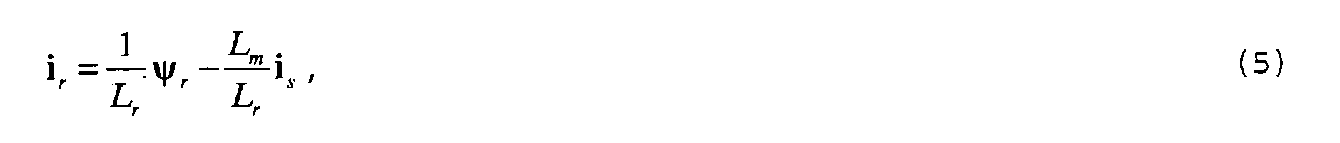
wobei L s , L r und L m die Statorinduktivität, die Rotorinduktivität und die Gegeninduktivität bezeichnet. - Das Umformen der Gleichungen (1) bis (5) führt zu einer günstigen Form der Differentialgleichung der Asynchronmaschine:


- Dabei ist die Variable w σ definiert als

- In den Gleichungen (6) bis (10) und im folgenden bezeichnet der erste Index jeweils den Ort (r: Rotor, s: Stator), der zweite Index gibt die jeweilige Komponente in einem zweiphasigen Koordinatensystem an (α, β), und der dritte Index bezeichnet das verwendete Bezugssystem (S: Statorwicklungsfest, R: Rotorwicklungsfest).
- Die vorliegende Erfindung geht von folgender Wahl der Zustandsvariablen zur Beschreibung des Zustands der Asynchronmaschine aus:
- Rotordrehzahl ω r ,
- Statorwirkleistung p s ,
- Statorblindleistung q s und
- Quadrat des Statorflusses

- Für die Rotordrehzahl ω r gilt die Beziehung:

- Die Momentanwerte der Generatorleistung lassen sich mittels der Gleichungen (13) und (14) beschreiben:


- Unter der Annahme eines stationären Zustandes lassen sich die Generatorleistungen wie folgt darstellen:


- Durch Differenzieren der Gleichungen (15) und (16) und durch Einsetzen der Gleichungen (6), (7), (8) und (9) erhält man nach Vereinfachung folgende Differentialgleichungen:


- Dabei ist

- Das Quadrat des Betrages des Statorflusses kann wie folgt berechnet werden:

- Durch Differenzieren von Gleichung (19) und durch Einsetzen der Gleichungen (6) und (7) erhält man folgende Differentialgleichung:

- Die vier Zustandsgleichungen des Systems, basierend auf der Wahl der vier Zustandsvariablen gemäß der vorliegenden Erfindung, können dann wie folgt zusammengefasst werden:


- Durch die erfindungsgemäße Wahl von Rotordrehzahl ω r , Statorwirkleistung p s , Statorblindleistung q s und Quadrat des Statorflusses

- Die Differentialgleichungen (22) und (23) sind auf Grund der starken Nichtlinearität für den Reglerentwurf jedoch nicht geeignet. Daher sieht die vorliegende Erfindung vor, das System der Zustandsgleichungen so umzuformen, dass die Wirk- und Blindleistung ein lineares Glied in der Systemmatrix bilden. Durch die Transformation des Systemzustandsdarstellung kann das System jedoch einen stark nichtlinearen Charakter erhalten. Dieses nichtlineare Verhalten wird wiederum durch nichtlineare Rückkopplungsglieder kompensiert. Im optimalen Fall soll das neu definierte System für jeweils die Wirkleistung und die Blindleistung ein Tiefpassverhalten erster Ordnung bekommen. Die Zeitkonstanten dieser Tiefpässe sind von der Zustandsmatrix des neu definierten Systems abhängig. Für das neu definierte System können dann zwei lineare Regler, z.B. zwei PI-Regler, eingesetzt werden.
- Die angestrebte Linearisierung der Zustandsgleichungen wird erreicht durch die Definition der Variablen:
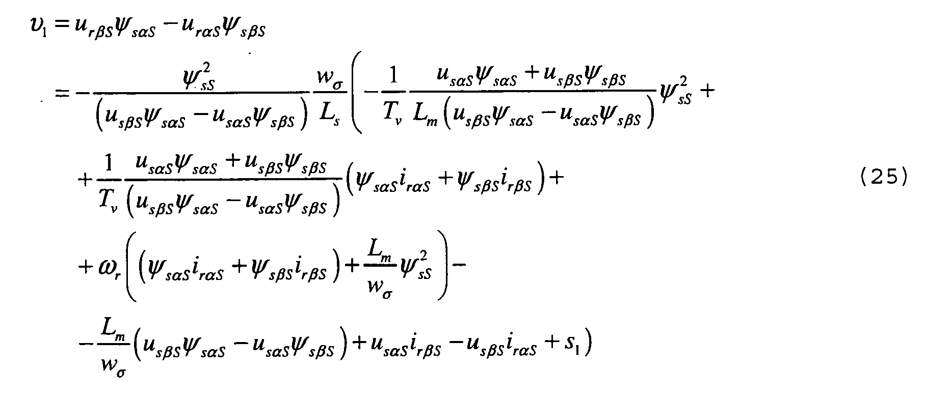
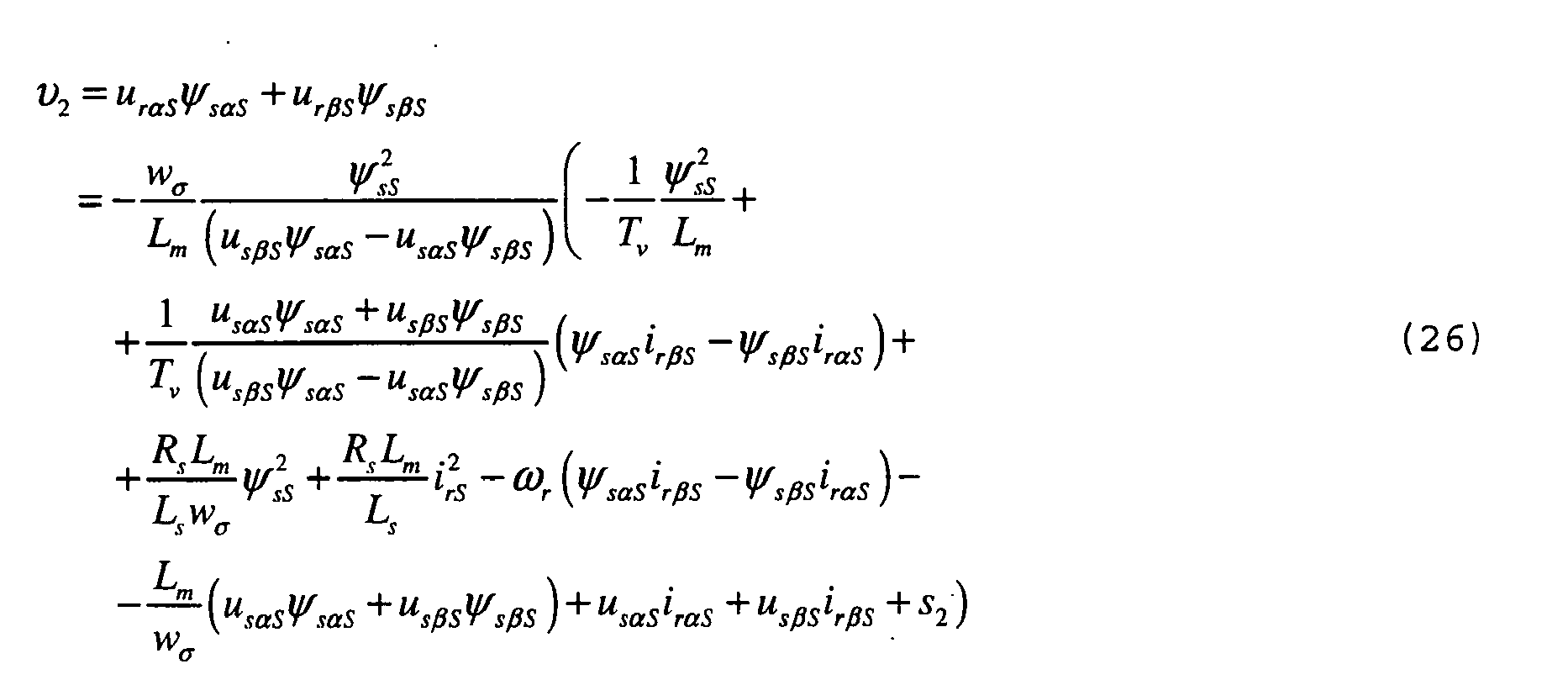
wobei die Größen s 1 und s 2 neu eingeführt werden, um eine Regelung des Systems zu ermöglichen. - Offensichtlich entspricht dabei v 1 aus Gleichung (25) dem Kreuzprodukt aus Rotorspannung und Statorfluss und v 2 aus Gleichung (26) dem Skalarprodukt von Rotorspannung und Statorfluss. Die Wahl der Zustandsvariablen und dieser Variablen v 1 und v 2 erlaubt es, in der erfindungsgemäßen Regelung auf die Information über die Raumzeigerlage zu verzichten, wodurch eine Regelung in einem wicklungsfesten Koordinatensystem ermöglicht wird, und trotz Nichtlinearität eine einfache Reglersynthese zu ermöglichen. Physikalisch hängt der Zustand der Asynchronmaschine 1 von der gegenseitigen Lage der Raumzeiger ab, die zur Beschreibung der Dynamik gewählt worden sind. Die Zusammenhänge zwischen Raumzeigern lassen sich jedoch auch ohne getrennte Winkelinformation durch Kreuz- und Skalarprodukte beschreiben. Die Zustandsvektoren gemäß der vorliegenden Erfindung wurden daher so gewählt, dass eine Beschreibung durch Kreuz- und Skalarprodukte möglich ist.
- Da es sich bei der Rotorspannung u rS (beschrieben durch die Komponenten u rαS und u rβS ) in den Gleichungen (25) und (26) um die Stellgröße der Regelung handelt, kann eine Berechnung der Variablen ν1 und ν2 nicht direkt über die Definition des Kreuz- und Skalarproduktes aus Rotorspannung und Statorfluss (vgl. jeweils die erste Zeile der Gleichungen (25) und (26)) erfolgen. Die Kreuz- und Skalarprodukte können jedoch gemäß den jeweils zweiten Zeilen der Gleichungen (25) und (26) durch Systemgrößen ausgedrückt und dadurch indirekt berechnet werden.
- Durch Einsetzen der Variablen ν1 und ν2 nach den Gleichungen (25) und (26) in die Gleichungen (22) und (23) erhält man die angestrebte Linearisierung der Zustandsgleichungen, die sich wie folgt zusammenfassen lassen:


- Die Gleichungen (27) bis (30) werden gemäß der vorliegenden Erfindung direkt zur Synthese der Regelung verwendet.
- Fig. 2 zeigt eine schematische Darstellung dieser Regelung. Dargestellt sind wiederum die doppeltgespeiste Asynchronmaschine 1 mit Stator 10 und Rotor 11, das speisende Netz 3 und der Umrichter 2.
- In diesem System werden nun zur Vornahme der erfindungsgemäßen Regelung der Wirk- und Blindleistung unterschiedliche Spannungen und Ströme gemessen und zur Regelung verwendet. Es sind dies im einzelnen die Netzspannung u N , der Netzstrom i N , die Statorspannung u sS und der Rotorstrom i rR . Diese Spannungen und Ströme werden in natürlichen dreiphasigen Koordinaten gemessen und anschließend mittels Transformationseinheiten 40-1, 40-2, 40-3 und 40-5 in ein zweiphasiges, statorfestes oder rotorfestes Koordinatensystem überführt. Beispielsweise liegt dann also die statorfeste Statorspannung u sS in zwei Komponenten u sαS und u sβS vor (entsprechend für die übrigen Spannungen und Ströme).
- Optional kann ferner der Statorstrom i sS gemessen und mittels einer Transformationseinheit 40-4 in ein zweiphasiges, statorfestes Koordinatensystem überführt werden, um eine Berechnung der Rotordrehzahl ω r und des Rotorlagewinkels ϕ RS zwischen Rotor und Stator zu ermöglichen.
- Alternativ zu dieser Vorgehensweise kann auch anhand eines optionalen Lagegebers 41 und eines optionalen Lageempfängers 42 die Rotordrehzahl ω r und der Rotorlagewinkel ϕ RS zwischen Rotor und Stator gemessen werden, eine Messung des Statorstroms ist dann nicht erforderlich.
- Aus der Netzspannung u N und dem Netzstrom i N wird in einer Leistungsberechnungseinheit 43 die Ist-Wirkleistung P und die Ist-Blindleistung Q berechnet und mit negativem Vorzeichen den Addierern 45-1 und 45-2 zugeführt, um durch Subtraktion von den extern vorgegebenen Soll-Wirkleistungen P Soll und Soll-Blindleistungen Q Soll jeweils eine Sollgrößenabweichung der Wirkleistung und eine Sollgrößenabweichung der Blindleistung an den Ausgängen der Addierer 45-1 und 45-2 zu erzeugen. In Fig. 2 ist die Regelung ausgehend von den Netzleistungen als Ist-Größen dargestellt. Es ist jedoch ohne weiteres möglich, anstelle der Netzleistungen zu Statorleistungen als Ist-Größen überzugehen.
- Die gemessenen und anschließend in ein zweiphasiges Koordinatensystem transformierten Größen u sS und i rR , und wahlweise die Messgrößen ω r und ϕ RS oder die gemessene und anschließend in ein zweiphasiges Koordinatensystem transformierte Größe i sS , die zur Berechnung von ω r und ϕ RS erforderlich ist, werden der Messgrößenverarbeitungseinheit 44 zugeführt, die in zumindest teilweiser Abhängigkeit von dieser Größen die Ausgangsgrößen Rotorlagewinkel ϕ RS , statorfester Statorfluss ψ sS und die Rückkopplungsgrößen v 1-s 1 und v 2-s 2 gemäß den Gleichungen (25) und (26) ausgibt. Auf die Berechnung dieser Ausgabegrößen wird im Zusammenhang mit der Beschreibung der Fig. 3 noch genauer eingegangen.
- Die in Fig. 2 dargestellte erfindungsgemäße Regelung verwendet die beiden PI-Regler 46-1 und 46-2, um in Abhängigkeit von Sollgrößenabweichungen der Wirkleistung und der Blindleistung Reglerausgangsgrößen s 1 und s 2 zu erzeugen. Die Reglerausgangsgrößen s 1 und s 2 werden getrennt den Addierern 45-3 und 45-4 zugeführt, wo sie durch Addition mit den Rückkopplungsgrößen v 1-s 1 und v 2-s 2 beaufschlagt werden, die von der Messgrößenverarbeitungseinheit 44 aus dem momentanen Systemzustand der Asynchronmaschine 1 bestimmt werden. Am Ausgang der Addierer 45-3 und 45-4 liegen dann die Größen v 1 und v 2 an, die der Einheit 47 zur Berechnung der Rotorspannung zugeführt werden.
- Die Einheit 47 erhält als zusätzliche Eingangsgröße den statorfesten Statorfluss ψ sS und bestimmt die zur Erzielung der vorgegebenen Wirkleistung P Soll und der vorgegebenen Blindleistung Q Soll erforderliche statorfeste Rotorspannung u rS (in einem zweiphasigem Koordinatensystem) gemäß den folgenden Gleichungen:


- Die Transformation der Rotorspannung aus dem statorfesten Koordinatensystem in das rotorfeste Koordinatensystem wird in der Transformationseinheit 48, die als zusätzliche Eingangsgröße von der Messgrößenverarbeitungseinheit 44 den Rotorlagewinkel ϕ RS erhält, nach folgender Vorschrift vorgenommen:


- Schließlich wird die rotorfeste Rotorspannung aus dem zweiphasigen Koordinatensystem durch die Transformationseinheit 40-6 in das dreiphasige Koordinatensystem transformiert und über den maschinenseitigen Pulswechselrichter 20 des Umrichters 2 dem Rotor 11 der Asynchronmaschine 1 eingeprägt.
- Die erfindungsgemäße Regelung benötigt lediglich die zwei PI-Regler 46-1 und 46-2, um die stationäre Sollwertabweichung der Wirkleistung und der Blindleistung mit ausreichender Geschwindigkeit auszuregeln. Hierzu sind die Parameter der PI-Regler, insbesondere die Zeitkonstanten der PI-Regler, an die Kenngrößen der Asynchronmaschine 1, wie sie in den Zustandsgleichungen ihren Niederschlag finden, angepasst.
- In Fig. 3 ist der schematische Aufbau der Messgrößenverarbeitungseinheit 44 aus Fig. 2 dargestellt. Die Messgrößenverarbeitungseinheit 44 erhält als Eingangsgrößen die gemessenen und anschließend in entsprechende zweiphasige Koordinatensystem transformierten Größen statorfeste Statorspannung u sS , rotorfester Rotorstrom i rR und wahlweise den statorfesten Statorstrom i sS oder die Rotordrehzahl ω r und den Rotorlagewinkel ϕ RS , und gibt in Abhängigkeit dieser Eingabegrößen den Rotorlagewinkel ϕ RS , den statorfesten Statorfluss ψ sS und die Rückkopplungsgrößen v 1 - s 1 und v 2 - s 2 aus.
- Wie bereits angedeutet, können die Rotordrehzahl ω r und der Rotorlagewinkel ϕ RS optional mittels des Lagegebers 41 und des Lageempfängers 42 aus Fig. 2 gemessen werden. Alternativ kann in der Messgrößenverarbeitungseinheit 44 auch eine Schätzung von Rotordrehzahl und Rotorlagewinkel aus der statorfesten Statorspannung u sS , dem statorfesten Statorstrom i sS und dem rotorfesten Rotorstrom i rR erfolgen, die dann in der Einheit 441 implementiert ist. Mittels der Schalter 442 und 443 kann dann jeweils zwischen gemessener/geschätzter Rotordrehzahl ω r und gemessenem/geschätztem Rotorlagewinkel ϕ RS gewählt werden. Natürlich kann aus Kostengründen auch eine der beiden Optionen Messung/Schätzung komplett entfallen.
- Der Rotorlagewinkel ϕ RS wird dann einerseits zur Transformation des rotorfesten Rotorstroms i rR auf den statorfesten Rotorstrom i rS in der Transformationseinheit 445 verwendet und andererseits von der Messgrößenverarbeitungseinheit 44 an die Transformationseinheit 48 aus Fig. 2 ausgegeben.
- Die Messgrößenverarbeitungseinheit 44 umfasst ferner eine Einheit 444 zur Berechnung des statorfesten Statorflusses ψ sS . Die Berechnung kann dabei nach einer beliebigen Methode erfolgen. Beispielsweise kann der Statorfluss nach Umwandlung der Gleichung (4) in folgender Form dargestellt werden:


- Bedingt durch Sättigungseffekte der Maschine oder durch die Art der Messwandler kann die oben dargestellte Methode zur Berechnung des Statorflusses zu Problemen führen. Es ist deshalb vorteilhaft, eine andere Methode zu verwenden. Bei Drehfeldmaschinen mit großer Leistung kann der Statorwiderstand R s vernachlässigt werden. Die Gleichung (1) nimmt damit folgende Form an:

- Aus Gleichung (37) ergibt sich im stationären Fall für die Komponenten des Statorflusses der folgende Zusammenhang:


- Dabei ist ω s die Kreisfrequenz der Statorspannung.
- Die Berechnung der Rückkopplungsgrößen v 1-s 1 und v 2-s 2 wird schließlich in der Einheit 446 in Abhängigkeit von u sS , ψ sS , i rS und ω r durchgeführt.
- In einer ersten bevorzugten Ausführungsform der vorliegenden Erfindung erfolgt die Berechnung der Rückkopplungsgrößen nach den Gleichungen (25) und (26).
- In einer zweiten bevorzugten Ausführungsform wird zur Herleitung der Gleichungen für die Rückkopplungsgrößen der Statorwiderstand R s vernachlässigt. Diese Annahme ist beispielsweise in großen Maschinen gerechtfertigt. In diesem Fall kann davon ausgegangen werden, dass die Statorspannung und der Statorfluss senkrecht aufeinander stehen. Wenn man weiterhin von einem stationären Zustand ausgeht und berücksichtigt, dass mit bezogenen Größen gerechnet wird, ergeben sich die folgenden Zusammenhänge:


- Die Berücksichtigung der Gleichungen (40), (41) und (42) führt zur Vereinfachung der Gleichungen (22) und (23). Diese lassen sich dann in der folgenden Form darstellen:


- Führt man wie bei der ersten bevorzugten Ausführungsform auch hier zur Linearisierung der Differentialgleichungen (43) und (44) Rückkopplungen ein, erhält man wiederum die Zustandsgleichungen nach den Gleichungen (27) bis (30), jedoch mit den veränderten Variablen
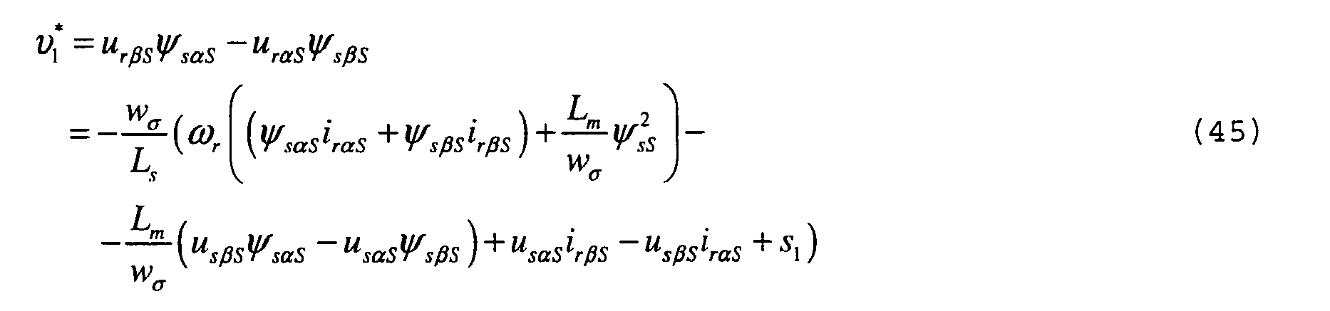

- Der einzige Unterschied zur ersten bevorzugten Ausführungsform besteht also in einer unterschiedlichen Berechnung der Rückkopplungen in der Einheit 446 der Messgrößenverarbeitungseinheit 44. Die sonstige Struktur der erfindungsgemäßen Regelung nach Fig. 2 und 3 bleibt erhalten.
- Durch die Vereinfachung der Rückkopplungsgrößen aus den Gleichungen (45) und (46) gemäß der zweiten bevorzugten Ausführungsform der vorliegenden Erfindung kann im Vergleich zur ersten bevorzugten Ausführungsform die Rückkopplung aufwandsgünstig berechnet und die Regelung damit weniger komplex und schneller durchgeführt werden. Modellabweichungen durch die Annahme eines vernachlässigbaren Statorwiderstandes werden dabei, wie alle anderen Störgrößen des Systems, durch die Regelung ausgeglichen, so dass sich bei der zweiten bevorzugten Ausführungsform kein Verlust in der Qualität oder Stabilität der Regelung ergibt.
- In einer dritten bevorzugten Ausführungsform wird schließlich bei der Herleitung der Rückkopplungen von einem stationären Zustand ausgegangen. Die Gleichungen (6) und (7) lassen sich dann wie folgt vereinfachen:


- Zuerst werden die Gleichungen (47) und (48) mit ψ sαS und ψ sβS multipliziert. Die dadurch entstehenden Gleichungen werden einmal subtrahiert und einmal addiert. So erhält man die Gleichungen:


- Durch das Einsetzen der Gleichungen (49) und (50) in die Gleichungen (15) und (16) ergeben sich folgende Leistungsgleichungen der Drehfeldmaschine:


- Durch Differenzieren der Gleichungen (51) und (52) und durch Einsetzen der Gleichungen (6) bis (9) erhält man nach Vereinfachung folgende Differentialgleichungen:


- Führt man wie bei der ersten und zweiten bevorzugten Ausführungsform auch hier zur Linearisierung der Differentialgleichungen (53) und (54) Rückkopplungen ein, erhält man wiederum die Zustandsgleichungen nach den Gleichungen (27) bis (30), jedoch mit den veränderten Variablen


- Der einzige Unterschied zur ersten und zweiten bevorzugten Ausführungsform besteht wiederum in einer unterschiedlichen Berechnung der Rückkopplungen in der Einheit 446 der Messgrößenverarbeitungseinheit 44. Die sonstige Struktur der erfindungsgemäßen Regelung nach Fig. 2 und 3 bleibt erhalten.
- Durch die Vereinfachung der Rückkopplungsgrößen aus den Gleichungen (55) und (56) gemäß der dritten bevorzugten Ausführungsform der vorliegenden Erfindung kann im Vergleich zur ersten bevorzugten Ausführungsform die Rückkopplung aufwandsgünstiger berechnet und die Regelung damit weniger komplex und schneller durchgeführt werden. Modellabweichungen durch die Annahme eines stationären Systemzustands werden dabei, wie alle anderen Störgrößen des Systems, durch die Regelung ausgeglichen, so dass sich auch bei der dritten bevorzugten Ausführungsform kein Verlust in der Qualität oder Stabilität der Regelung ergibt.
- Die vorliegende Erfindung wurde anhand von bevorzugten Ausführungsformen beschreiben. Durch Verwendung von unterschiedlichen Vereinfachungen bei der Herleitung der Zustandsgleichungen ergeben sich mehrere Varianten der erfindungsgemäßen Regelung. Eine derartige Regelung zeichnet sich durch große Genauigkeit und Dynamik aus. Für die Steuerung des Umrichters ist keine Transformation der Messgrößen auf ein bestimmtes Bezugssystem notwendig. Das Koordinatensystem kann also frei gewählt werden. Der Einfachheit halber kann beispielsweise ein statorfestes Koordinatensystem gewählt werden.
Claims (40)
- Ein Verfahren zur Regelung der von einer Drehfeldmaschine (1) abgegebenen oder aufgenommenen Wirk- und Blindleistung in einem wicklungsfesten Koordinatensystem, wobei in Abhängigkeit einer Sollgrößenabweichung der Wirkleistung mit einem ersten Regler (46-1) eine erste Reglerausgangsgröße erzeugt wird und in Abhängigkeit einer Sollgrößenabweichung der Blindleistung mit einem zweiten Regler (46-2) eine zweite Reglerausgangsgröße erzeugt wird, und wobei die erste und zweite Reglerausgangsgröße mit jeweiligen Rückkopplungsgrößen beaufschlagt werden, die Funktionen aus mindestens einer zeitveränderlichen Systemgröße der Drehfeldmaschine sind, dadurch gekennzeichnet, dass zumindest aus den mit den Rückkopplungsgrößen beaufschlagten ersten und zweiten Reglerausgangsgrößen ohne weitere Regelung eine Spannung oder ein Strom der Drehfeldmaschine als Stellgröße bestimmt wird.
- Das Verfahren nach Anspruch 1, dadurch gekennzeichnet, dass die Regler (46-1, 46-2) lineare Regler sind.
- Das Verfahren nach einem der Ansprüche 1-2, dadurch gekennzeichnet, dass die Regler (46-1, 46-2) PI-Regler sind.
- Das Verfahren nach einem der Ansprüche 1-3, dadurch gekennzeichnet, dass als Stellgröße eine Rotorspannung der Drehfeldmaschine (1) bestimmt wird.
- Das Verfahren nach einem der Ansprüche 1-3, dadurch gekennzeichnet, dass als Stellgröße eine Statorspannung der Drehfeldmaschine (1) bestimmt wird.
- Das Verfahren nach einem der Ansprüche 1-3, dadurch gekennzeichnet, dass als Stellgröße ein Erregerstrom der Drehfeldmaschine (1) bestimmt wird.
- Das Verfahren nach einem der Ansprüche 1-6, dadurch gekennzeichnet, dass bei der Berechnung der Rückkopplungsgrößen der Ohmsche Widerstand des Stators der Drehfeldmaschine (1) vernachlässigt wird.
- Das Verfahren nach einem der Ansprüche 1-6, dadurch gekennzeichnet, dass bei der Berechnung der Rückkopplungsgrößen von einem stationären Zustand ausgegangen wird.
- Das Verfahren nach einem der Ansprüche 1-8, dadurch gekennzeichnet, dass die Wirk- und Blindleistung des Stators (10) der Drehfeldmaschine (1) geregelt werden.
- Das Verfahren nach einem der Ansprüche 1-8, dadurch gekennzeichnet, dass die Wirk- und Blindleistung des Netzes (3), an das die Drehfeldmaschine (1) angeschlossen ist, geregelt werden.
- Das Verfahren nach einem der Ansprüche 1-10, dadurch gekennzeichnet, dass die erste Reglerausgangsgröße mit einer Rückkopplungsgröße beaufschlagt wird, die dem Kreuzprodukt von Rotorspannung und Statorfluss der Drehfeldmaschine entspricht, und dass die zweite Reglerausgangsgröße mit einer Rückkopplungsgröße beaufschlagt wird, die dem Skalarprodukt von Rotorspannung und Statorfluss entspricht.
- Das Verfahren nach einem der Ansprüche 1-11, dadurch gekennzeichnet, dass die Rückkopplungsgrößen Funktionen zumindest der Statorspannung, des Statorflusses, des Rotorstroms und der Rotordrehzahl sind.
- Das Verfahren nach einem der Ansprüche 1-12, dadurch gekennzeichnet, dass die Rotorspannung der Drehfeldmaschine als Stellgröße ohne weitere Regelung aus den mit den Rückkopplungsgrößen beaufschlagten ersten und zweiten Reglerausgangsgrößen und dem Statorfluss bestimmt wird.
- Das Verfahren nach einem der Ansprüche 1-13, dadurch gekennzeichnet, dass zumindest die Statorspannung und der Rotorstrom der Drehfeldmaschine (1) gemessen werden.
- Das Verfahren nach einem der Ansprüche 1-14, dadurch gekennzeichnet, dass der Statorstrom der Drehfeldmaschine (1) gemessen wird.
- Das Verfahren nach einem der Ansprüche 1-15, dadurch gekennzeichnet, dass die Rotordrehzahl der Drehfeldmaschine (1) gemessen oder aus der Statorspannung, dem Statorstrom und dem Rotorstrom der Drehfeldmaschine bestimmt wird.
- Das Verfahren nach einem der Ansprüche 1-16, dadurch gekennzeichnet, dass der Rotorlagewinkel der Drehfeldmaschine (1) gemessen oder aus der Statorspannung, dem Statorstrom und dem Rotorstrom der Drehfeldmaschine bestimmt wird.
- Das Verfahren nach einem der Ansprüche 1-17, dadurch gekennzeichnet, dass der Statorfluss der Drehfeldmaschine (1) aus der Statorspannung und der Kreisfrequenz der Statorspannung der Drehfeldmaschine berechnet wird.
- Das Verfahren nach einem der Ansprüche 14-18, dadurch gekennzeichnet, dass Spannungen und Ströme der Drehfeldmaschine (1) jeweils gemessen und dann in ein zweiphasiges Koordinatensystem transformiert werden, und dass die Stellgröße in einem zweiphasigen Koordinatensystem bestimmt und dann in ein dreiphasiges Koordinatensystem transformiert wird.
- Das Verfahren nach einem der Ansprüche 1-19, dadurch gekennzeichnet, dass die Drehfeldmaschine (1) eine doppeltgespeiste Asynchronmaschine ist, deren Stator (10) direkt mit einem Netz (3) verbunden ist, und deren Rotor (11) mit einem Umrichter (2)verbunden ist.
- Ein Computerprogramm mit Befehlen, deren Ausführung einen Prozessor veranlasst, das Verfahren gemäß einem der Ansprüche 1-20 durchzuführen.
- Ein Computerprogrammprodukt, das ein Computerprogramm enthält mit Befehlen, deren Ausführung einen Prozessor veranlasst, das Verfahren gemäß einem der Ansprüche 1-20 durchzuführen.
- Eine Vorrichtung zur Regelung der von einer Drehfeldmaschine (1) abgegebenen oder aufgenommenen Wirk- und Blindleistung in einem wicklungsfesten Koordinatensystem, mit einem ersten Regler (46-1) zur Erzeugung einer ersten Reglerausgangsgröße bei Sollgrößenabweichungen der Wirkleistung, mit einem zweiten Regler (46-2) zur Erzeugung einer zweiten Reglerausgangsgröße bei Sollgrößenabweichungen der Blindleistung, und mit Mitteln (44, 45-3, 45-4) zur Beaufschlagung der ersten und zweiten Reglerausgangsgröße mit jeweiligen Rückkopplungsgrößen, die sich als Funktionen aus mindestens einer zeitveränderlichen Systemgröße der Drehfeldmaschine ergeben, dadurch gekennzeichnet, dass die Vorrichtung Mittel (47) zur Bestimmung einer Spannung oder eines Stroms der Drehfeldmaschine als Stellgröße aus zumindest den mit den Rückkopplungsgrößen beaufschlagten ersten und zweiten Reglerausgangsgrößen ohne weitere Regelung umfasst.
- Die Vorrichtung nach Anspruch 23, dadurch gekennzeichnet, dass die Regler (46-1, 46-2) lineare Regler sind.
- Die Vorrichtung nach einem der Ansprüche 23-24, dadurch gekennzeichnet, dass die Regler (46-1, 46-2) PI-Regler sind.
- Die Vorrichtung nach einem der Ansprüche 23-25, dadurch gekennzeichnet, dass das Mittel (47) zur Bestimmung einer Spannung oder eines Stroms der Drehfeldmaschine (1) eine Rotorspannung als Stellgröße bestimmt.
- Die Vorrichtung nach einem der Ansprüche 23-25, dadurch gekennzeichnet, dass das Mittel (47) zur Bestimmung einer Spannung oder eines Stroms der Drehfeldmaschine (1) eine Statorspannung als Stellgröße bestimmt.
- Die Vorrichtung nach einem der Ansprüche 23-25, dadurch gekennzeichnet, dass das Mittel (47) zur Bestimmung einer Spannung oder eines Stroms der Drehfeldmaschine (1) einen Erregerstrom als Stellgröße bestimmt.
- Die Vorrichtung nach einem der Ansprüche 23-28, dadurch gekennzeichnet, dass die Wirk- und Blindleistung des Stators (10) der Drehfeldmaschine (1) geregelt werden.
- Die Vorrichtung nach einem der Ansprüche 23-28, dadurch gekennzeichnet, dass die Wirk- und Blindleistung des Netzes (3), an das die Drehfeldmaschine (1) angeschlossen ist, geregelt werden.
- Die Vorrichtung nach einem der Ansprüche 23-30, dadurch gekennzeichnet, dass die Reglerausgangsgröße des ersten Reglers (46-1) mit einer Rückkopplungsgröße beaufschlagt wird, die dem Kreuzprodukt von Rotorspannung und Statorfluss der Drehfeldmaschine (1) entspricht, und dass die Reglerausgangsgröße des zweiten Reglers (46-2) mit einer Rückkopplungsgröße beaufschlagt wird, die dem Skalarprodukt von Rotorspannung und Statorfluss entspricht.
- Die Vorrichtung nach einem der Ansprüche 23-31, dadurch gekennzeichnet, dass die Rückkopplungsgrößen Funktionen zumindest der Statorspannung, des Statorflusses, des Rotorstroms und der Rotordrehzahl sind.
- Die Vorrichtung nach einem der Ansprüche 23-32, dadurch gekennzeichnet, dass die Rotorspannung der Drehfeldmaschine (1) als Stellgröße aus den mit den Rückkopplungsgrößen beaufschlagten ersten und zweiten Reglerausgangsgrößen und dem Statorfluss ohne weitere Regelung bestimmt wird.
- Die Vorrichtung nach einem der Ansprüche 23-33, dadurch gekennzeichnet, dass die Vorrichtung Mittel zur Messung der Statorspannung und des Rotorstroms der Drehfeldmaschine (1) umfasst.
- Die Vorrichtung nach einem der Ansprüche 23-34, dadurch gekennzeichnet, dass die Vorrichtung Mittel zur Messung des Statorstroms umfasst.
- Die Vorrichtung nach einem der Ansprüche 23-35, dadurch gekennzeichnet, dass die Vorrichtung Mittel zur Messung (41, 42) der Rotordrehzahl der Drehfeldmaschine (1) oder zu deren Bestimmung (441) aus der Statorspannung, dem Statorstrom und dem Rotorstrom der Drehfeldmaschine umfasst.
- Die Vorrichtung nach einem der Ansprüche 23-36, dadurch gekennzeichnet, dass die Vorrichtung Mittel zur Messung (41, 42) des Rotorlagewinkels der Drehfeldmaschine (1) oder zu dessen Bestimmung (441) aus der Statorspannung, dem Statorstrom und dem Rotorstrom der Drehfeldmaschine umfasst.
- Die Vorrichtung nach einem der Ansprüche 34-37, dadurch gekennzeichnet, dass die Vorrichtung Mittel zur Messung der Spannungen und Ströme der Drehfeldmaschine (1) und zu deren Transformation (40-1, 40-2, 40-3, 40-4, 40-5) in ein zweiphasiges Koordinatensystem umfasst, und dass die Vorrichtung Mittel (40-6) zur Transformation der in einem zweiphasigen Koordinatensystem bestimmten Stellgröße in ein dreiphasiges Koordinatensystem umfasst.
- Die Vorrichtung nach einem der Ansprüche 23-38, dadurch gekennzeichnet, dass die Drehfeldmaschine (1) eine doppeltgespeiste Asynchronmaschine ist, deren Stator (10) direkt mit einem Netz (3) verbunden ist, und deren Rotor (11) mit einem Umrichter (2) verbunden ist.
- Eine Drehfeldmaschine (1) mit einer Vorrichtung zur Regelung der von der Drehfeldmaschine abgegebenen oder aufgenommenen Wirk- und Blindleistung in einem wicklungsfesten Koordinatensystem nach einem der Ansprüche 23-39.
Priority Applications (13)
| Application Number | Priority Date | Filing Date | Title |
|---|---|---|---|
| DE502004008691T DE502004008691D1 (de) | 2004-08-27 | 2004-08-27 | Leistungsregelung für Drehfeldmaschinen |
| EP04020382A EP1630948B1 (de) | 2004-08-27 | 2004-08-27 | Leistungsregelung für Drehfeldmaschinen |
| ES04020382T ES2319647T3 (es) | 2004-08-27 | 2004-08-27 | Regulacion de potencia de maquinas de campo giratorio. |
| PL04020382T PL1630948T3 (pl) | 2004-08-27 | 2004-08-27 | Regulacja mocy dla maszyn o wirującym polu magnetycznym |
| AT04020382T ATE418178T1 (de) | 2004-08-27 | 2004-08-27 | Leistungsregelung für drehfeldmaschinen |
| DK04020382T DK1630948T3 (da) | 2004-08-27 | 2004-08-27 | Effektregulering for maskiner med et roterende magnetfelt |
| PT04020382T PT1630948E (pt) | 2004-08-27 | 2004-08-27 | Regulação da potência em máquinas de indução |
| US10/572,235 US7423406B2 (en) | 2004-08-27 | 2005-07-29 | Power control of an induction machine |
| PCT/EP2005/008244 WO2006024350A1 (de) | 2004-08-27 | 2005-07-29 | Leistungsregelung für drehfeldmaschinen |
| CA002576809A CA2576809A1 (en) | 2004-08-27 | 2005-07-29 | Power control of an induction machine |
| JP2007528646A JP2008511274A (ja) | 2004-08-27 | 2005-07-29 | 誘導機の電力調整方法および装置 |
| AU2005279456A AU2005279456B2 (en) | 2004-08-27 | 2005-07-29 | Power control of an induction machine |
| CN2005800287496A CN101053137B (zh) | 2004-08-27 | 2005-07-29 | 感应式电机及其功率调节方法和设备 |
Applications Claiming Priority (1)
| Application Number | Priority Date | Filing Date | Title |
|---|---|---|---|
| EP04020382A EP1630948B1 (de) | 2004-08-27 | 2004-08-27 | Leistungsregelung für Drehfeldmaschinen |
Publications (2)
| Publication Number | Publication Date |
|---|---|
| EP1630948A1 true EP1630948A1 (de) | 2006-03-01 |
| EP1630948B1 EP1630948B1 (de) | 2008-12-17 |
Family
ID=34926329
Family Applications (1)
| Application Number | Title | Priority Date | Filing Date |
|---|---|---|---|
| EP04020382A Active EP1630948B1 (de) | 2004-08-27 | 2004-08-27 | Leistungsregelung für Drehfeldmaschinen |
Country Status (13)
| Country | Link |
|---|---|
| US (1) | US7423406B2 (de) |
| EP (1) | EP1630948B1 (de) |
| JP (1) | JP2008511274A (de) |
| CN (1) | CN101053137B (de) |
| AT (1) | ATE418178T1 (de) |
| AU (1) | AU2005279456B2 (de) |
| CA (1) | CA2576809A1 (de) |
| DE (1) | DE502004008691D1 (de) |
| DK (1) | DK1630948T3 (de) |
| ES (1) | ES2319647T3 (de) |
| PL (1) | PL1630948T3 (de) |
| PT (1) | PT1630948E (de) |
| WO (1) | WO2006024350A1 (de) |
Cited By (2)
| Publication number | Priority date | Publication date | Assignee | Title |
|---|---|---|---|---|
| WO2010028689A1 (en) * | 2008-09-11 | 2010-03-18 | Woodward Seg Gmbh & Co. Kg | Direct power control with component separation |
| CN113131491A (zh) * | 2021-04-25 | 2021-07-16 | 哈尔滨理工大学 | 一种调相机转子静止状态下无功调节方法及装置 |
Families Citing this family (28)
| Publication number | Priority date | Publication date | Assignee | Title |
|---|---|---|---|---|
| DE102006027465A1 (de) * | 2006-06-12 | 2007-12-13 | Woodward Seg Gmbh & Co. Kg | Strombegrenzung für eine doppeltgespeiste Asynchronmaschine |
| JP2008011607A (ja) * | 2006-06-28 | 2008-01-17 | Hitachi Ltd | 可変速風力発電システム |
| WO2008081049A1 (es) * | 2006-12-28 | 2008-07-10 | Wind To Power System, S.L. | Generador asíncrono con control de la tensión aplicada al estator |
| US20080297170A1 (en) * | 2007-05-28 | 2008-12-04 | Tektronix, Inc. | Dynamic inductance measurement of electric motor |
| DE102007032179A1 (de) * | 2007-07-10 | 2009-01-22 | Repower Systems Ag | Windenergieanlage mit erweitertem Drehzahlbereich |
| DE102008007448A1 (de) * | 2008-02-01 | 2009-08-13 | Woodward Seg Gmbh & Co. Kg | Verfahren zum Betreiben einer Windenergieanlage |
| US8227929B2 (en) * | 2009-09-25 | 2012-07-24 | General Electric Company | Multi-use energy storage for renewable sources |
| US8018082B2 (en) * | 2009-11-25 | 2011-09-13 | General Electric Company | Method and apparatus for controlling a wind turbine |
| IT1397441B1 (it) * | 2009-12-30 | 2013-01-10 | Ansaldo Electric Drives S P A Ora Ansaldo En Holding S P A | Dispositivo di controllo per una macchina elettrica asincrona, sistema elettrico di propulsione comprendente detto dispositivo e metodo per controllare una macchina elettrica asincrona |
| IT1397977B1 (it) * | 2009-12-30 | 2013-02-04 | Ansaldo Electric Drives S P A Ora Ansaldo En Holding S P A | Dispositivo di controllo per una macchina elettrica asincrona, sistema elettrico di propulsione comprendente detto dispositivo e metodo per controllare una macchina elettrica asincrona |
| JP5320311B2 (ja) * | 2010-01-18 | 2013-10-23 | 三菱重工業株式会社 | 可変速発電装置及びその制御方法 |
| CN101814893B (zh) * | 2010-04-16 | 2012-03-14 | 阳光电源股份有限公司 | 双馈式风力发电机组定子电流不平衡抑制方法 |
| KR101243181B1 (ko) * | 2010-11-04 | 2013-03-14 | 한국전기연구원 | 궤환선형화 방법을 이용한 권선형유도발전기 제어장치 |
| DE102011000459B4 (de) * | 2011-02-02 | 2017-11-02 | Universität Kassel | Verfahren zur Lieferung von Blindstrom mit einem Umrichter sowie Umrichteranordnung und Energieversorgungsanlage |
| CN102969931A (zh) * | 2012-11-15 | 2013-03-13 | 苏州天辰马智能设备有限公司 | 单电阻电流采样的pwm整流型能量回馈装置的控制方法 |
| CN104980075B (zh) * | 2014-04-11 | 2018-05-01 | 维谛技术有限公司 | 一种双馈电机的控制系统及控制方法 |
| CN105099313B (zh) * | 2014-05-20 | 2017-11-21 | 艾默生网络能源有限公司 | 一种双馈电机的控制系统及控制方法 |
| JP6488881B2 (ja) * | 2015-05-20 | 2019-03-27 | 富士電機株式会社 | シミュレーション装置及びシミュレーションシステム |
| WO2017019647A1 (en) | 2015-07-24 | 2017-02-02 | Videoamp, Inc. | Cross-screen measurement accuracy in advertising performance |
| CN108352025B (zh) | 2015-07-24 | 2022-10-11 | 安普视频有限公司 | 基于消费者在线行为的电视广告时段定位 |
| WO2017019646A1 (en) | 2015-07-24 | 2017-02-02 | Videoamp, Inc. | Sequential delivery of advertising content across media devices |
| US10812870B2 (en) | 2016-01-14 | 2020-10-20 | Videoamp, Inc. | Yield optimization of cross-screen advertising placement |
| CN113473187B (zh) | 2015-07-24 | 2023-10-10 | 安普视频有限公司 | 广告投放的跨屏优化 |
| US10136174B2 (en) | 2015-07-24 | 2018-11-20 | Videoamp, Inc. | Programmatic TV advertising placement using cross-screen consumer data |
| CN105337543B (zh) * | 2015-12-09 | 2018-03-13 | 武汉大学 | 一种双馈风机转子侧输出功率控制方法 |
| FR3053183B1 (fr) * | 2016-06-22 | 2018-06-22 | Renault S.A.S | Procede d'estimation de la position et de la vitesse du rotor d'une machine a courant alternatif pour vehicule automobile et systeme correspondant |
| PT3748797T (pt) * | 2019-06-07 | 2022-12-02 | Ge Energy Power Conversion Technology Ltd | Método de operacionalização de sistemas de gerador de indução de alimentação dupla e gerador de indução de alimentação dupla |
| DE102020111333A1 (de) * | 2020-04-27 | 2021-10-28 | Audi Aktiengesellschaft | Verfahren zum Vergießen eines FSM-Rotors und FSM-Rotor mit Hybridrotorverguss |
Citations (4)
| Publication number | Priority date | Publication date | Assignee | Title |
|---|---|---|---|---|
| DE4032056C1 (en) * | 1990-10-05 | 1992-05-21 | Mannesmann Ag, 4000 Duesseldorf, De | Determining slip frequency for control of asynchronous motor - calculating cross product of stator current voltage and frequency vectors to increase stator frequency bandwidth towards DC |
| US5798631A (en) * | 1995-10-02 | 1998-08-25 | The State Of Oregon Acting By And Through The State Board Of Higher Education On Behalf Of Oregon State University | Performance optimization controller and control method for doubly-fed machines |
| US6448735B1 (en) * | 2001-04-26 | 2002-09-10 | Abb Automation Inc. | Controller for a wound rotor slip ring induction machine |
| WO2004107556A1 (en) * | 2003-05-27 | 2004-12-09 | Abb Oy | Method for controlling doubly-fed machine |
Family Cites Families (17)
| Publication number | Priority date | Publication date | Assignee | Title |
|---|---|---|---|---|
| DE1563741B2 (de) * | 1966-09-03 | 1976-06-24 | Siemens AG, 1000 Berlin und 8000 München | Einrichtung zur laeuferstromregelung einer doppeltgespeisten drehstrommaschine |
| DE3026202A1 (de) * | 1980-07-10 | 1982-02-04 | Siemens AG, 1000 Berlin und 8000 München | Drehfeldmaschinenantrieb mit einer umrichtergespeisten drehfeldmaschine und einer mit zwei wechselspannungsintegratoren und einer rechenmodellschaltung verbundenen umrichtersteuerung |
| DE3034251A1 (de) * | 1980-09-11 | 1982-04-15 | Siemens AG, 1000 Berlin und 8000 München | Verfahren und vorrichtung zum ermitteln des laeuferwiderstandes einer asynchronmaschine |
| JPS62185579A (ja) * | 1986-02-07 | 1987-08-13 | Mitsubishi Electric Corp | 誘導電動機の電力制御装置 |
| DE3870056D1 (de) * | 1987-07-07 | 1992-05-21 | Bbc Brown Boveri & Cie | Verfahren und einrichtung zum betrieb einer drehfeldmaschine. |
| JP2533930B2 (ja) * | 1989-03-18 | 1996-09-11 | 富士電機株式会社 | 巻線形誘導発電機の電力制御方法 |
| DE59008677D1 (de) * | 1990-12-10 | 1995-04-13 | Asea Brown Boveri | Verfahren und Vorrichtung zur Eliminierung oder Reduzierung von Oberschwingungen und/oder Resonanzschwingungen. |
| KR950010191B1 (ko) * | 1991-09-18 | 1995-09-11 | 삼성전자주식회사 | 유도전동기의 회전자저항 추정장치 |
| US5668459A (en) * | 1995-05-09 | 1997-09-16 | Lg Industrial Systems Co., Ltd. | Apparatus for generating magnetic flux of induction motor |
| US5796236A (en) * | 1997-06-30 | 1998-08-18 | Reliance Electric Industrial Company | Slip adjuster for use in electrical motor controllers |
| FI112414B (fi) * | 2001-03-19 | 2003-11-28 | Abb Industry Oy | Menetelmä vaihtosuuntaajan yhteydessä |
| JP4003414B2 (ja) * | 2001-06-29 | 2007-11-07 | 株式会社日立製作所 | 永久磁石式発電機を用いた発電装置 |
| JP3982232B2 (ja) * | 2001-10-25 | 2007-09-26 | 株式会社日立製作所 | 同期発電機のセンサレス制御装置と制御方法 |
| US6876169B2 (en) * | 2003-01-14 | 2005-04-05 | Delphi Technologies, Inc. | Method and controller for field weakening operation of AC machines |
| KR20050003732A (ko) * | 2003-07-04 | 2005-01-12 | 현대자동차주식회사 | 유도 전동기용 벡터 제어형 듀얼 인버터 시스템 |
| US6984960B2 (en) * | 2003-08-05 | 2006-01-10 | General Motors Corporation | Methods and apparatus for current control of a three-phase voltage source inverter in the overmodulation region |
| DE10355423A1 (de) * | 2003-11-27 | 2005-07-14 | Siemens Ag | Verfahren zur Erkennung eines fehlerhaften Rotorlagewinkelsignals sowie Einrichtungen zur Durchführung des Verfahrens |
-
2004
- 2004-08-27 PL PL04020382T patent/PL1630948T3/pl unknown
- 2004-08-27 AT AT04020382T patent/ATE418178T1/de not_active IP Right Cessation
- 2004-08-27 PT PT04020382T patent/PT1630948E/pt unknown
- 2004-08-27 EP EP04020382A patent/EP1630948B1/de active Active
- 2004-08-27 ES ES04020382T patent/ES2319647T3/es active Active
- 2004-08-27 DE DE502004008691T patent/DE502004008691D1/de active Active
- 2004-08-27 DK DK04020382T patent/DK1630948T3/da active
-
2005
- 2005-07-29 CN CN2005800287496A patent/CN101053137B/zh active Active
- 2005-07-29 CA CA002576809A patent/CA2576809A1/en not_active Abandoned
- 2005-07-29 US US10/572,235 patent/US7423406B2/en active Active
- 2005-07-29 AU AU2005279456A patent/AU2005279456B2/en not_active Ceased
- 2005-07-29 JP JP2007528646A patent/JP2008511274A/ja active Pending
- 2005-07-29 WO PCT/EP2005/008244 patent/WO2006024350A1/de active Application Filing
Patent Citations (4)
| Publication number | Priority date | Publication date | Assignee | Title |
|---|---|---|---|---|
| DE4032056C1 (en) * | 1990-10-05 | 1992-05-21 | Mannesmann Ag, 4000 Duesseldorf, De | Determining slip frequency for control of asynchronous motor - calculating cross product of stator current voltage and frequency vectors to increase stator frequency bandwidth towards DC |
| US5798631A (en) * | 1995-10-02 | 1998-08-25 | The State Of Oregon Acting By And Through The State Board Of Higher Education On Behalf Of Oregon State University | Performance optimization controller and control method for doubly-fed machines |
| US6448735B1 (en) * | 2001-04-26 | 2002-09-10 | Abb Automation Inc. | Controller for a wound rotor slip ring induction machine |
| WO2004107556A1 (en) * | 2003-05-27 | 2004-12-09 | Abb Oy | Method for controlling doubly-fed machine |
Non-Patent Citations (1)
| Title |
|---|
| KRZEMINSKI Z: "Sensorless multiscalar control of double fed machine for wind power generators", 2 April 2002, POWER CONVERSION CONFERENCE, 2002. PCC-OSAKA 2002. PROCEEDINGS OF THE OSAKA, JAPAN 2-5 APRIL 2002, PISCATAWAY, NJ, USA,IEEE, US, PAGE(S) 334-339, ISBN: 0-7803-7156-9, XP010590475 * |
Cited By (5)
| Publication number | Priority date | Publication date | Assignee | Title |
|---|---|---|---|---|
| WO2010028689A1 (en) * | 2008-09-11 | 2010-03-18 | Woodward Seg Gmbh & Co. Kg | Direct power control with component separation |
| US8698461B2 (en) | 2008-09-11 | 2014-04-15 | Woodward Kempen Gmbh | Direct power control with component separation |
| CN102150356B (zh) * | 2008-09-11 | 2015-01-07 | 伍德沃德肯彭有限公司 | 具有分量分离的直接功率控制 |
| CN113131491A (zh) * | 2021-04-25 | 2021-07-16 | 哈尔滨理工大学 | 一种调相机转子静止状态下无功调节方法及装置 |
| CN113131491B (zh) * | 2021-04-25 | 2022-08-30 | 哈尔滨理工大学 | 一种调相机转子静止状态下无功调节方法及装置 |
Also Published As
| Publication number | Publication date |
|---|---|
| DE502004008691D1 (de) | 2009-01-29 |
| PT1630948E (pt) | 2009-03-20 |
| AU2005279456A1 (en) | 2006-03-09 |
| CN101053137B (zh) | 2010-10-13 |
| US20070052394A1 (en) | 2007-03-08 |
| CA2576809A1 (en) | 2006-03-09 |
| ES2319647T3 (es) | 2009-05-11 |
| WO2006024350A1 (de) | 2006-03-09 |
| ATE418178T1 (de) | 2009-01-15 |
| AU2005279456B2 (en) | 2010-01-28 |
| PL1630948T3 (pl) | 2009-06-30 |
| EP1630948B1 (de) | 2008-12-17 |
| CN101053137A (zh) | 2007-10-10 |
| JP2008511274A (ja) | 2008-04-10 |
| DK1630948T3 (da) | 2009-04-14 |
| US7423406B2 (en) | 2008-09-09 |
Similar Documents
| Publication | Publication Date | Title |
|---|---|---|
| EP1630948B1 (de) | Leistungsregelung für Drehfeldmaschinen | |
| EP2070174B1 (de) | Konditionierungseinrichtung für energieversorgungsnetze | |
| EP1652289B1 (de) | Verfahren zur gesteuerten einprägung eines ständerstrom- und eines drehmoment-sollwertes für eine stromrichtergespeiste drehfeldmaschine | |
| EP2179498B1 (de) | Verfahren und vorrichtung zur kompensation von schwingungseffekten bei netzunsymmetrie bei einer doppeltgespeisten asynchronmaschine | |
| EP2027648B1 (de) | Strombegrenzung für eine doppeltgespeiste asynchronmaschine | |
| DE10060368B4 (de) | Verfahren zum Steuern eines Asynchronmotors und Gerät zum Ausführen desselben | |
| EP0043973A1 (de) | Drehfeldmaschinenantrieb mit einer umrichtergespeisten Drehfeldmaschine und einer mit zwei Wechselspannungsintegratoren und einer Rechenmodellschaltung verbundenen Umrichtersteuerung | |
| DE10206191B4 (de) | Verfahren zur feldorientierten Regelung einer permanenterregten Synchronmaschine mit Reluktanzmoment | |
| EP2433356B1 (de) | Überstrombegrenzung bei der regelung von stromrichtergespeisten drehstrommaschinen | |
| DE102015205348A1 (de) | Verfahren zum Steuern eines Synchrongenerators einer getriebelosen Windenergieanlage | |
| DE19913941A1 (de) | Steuergerät zur variablen Steuerung der Drehzahl eines Asynchronmotors | |
| DE112014007197T5 (de) | Antriebs-steuerungsvorrichtung für einen mehrwicklungsmotor | |
| EP0491881B1 (de) | Verfahren zur flussollwertkorrektur einer umrichtergespeisten, mehrphasigen maschine und schaltungsanordnung zur durchführung des verfahrens | |
| EP2001123A1 (de) | Verfahren zum Betrieb einer dreiphasigen rotierenden elektrischen Maschine sowie Vorrichtung zur Durchführung des Verfahrens | |
| DE102018207583A1 (de) | Verfahren, Computerprogrammprodukt und System zum Betreiben einer Asynchronmaschine sowie Asynchronmaschine | |
| DE102010021488A1 (de) | Verfahren zur (kupfer-)verlustoptimalen Regelung einer Asynchronmaschine mit einem Frequenzumrichter | |
| DE102008007100A1 (de) | Verfahren und Vorrichtung zur Stromregelung oder Momentenregelung | |
| DE102015216309B4 (de) | Verfahren zur feldorientierten Regelung eines Frequenzumrichters für einen Drehstrommotor | |
| DE10204110B4 (de) | Motortreiberschaltkreis und Verfahren zur Steuerung des Motortreiberschaltkreises | |
| DE102017012027A1 (de) | Verfahren zur drehgeberlosen Rotorlagebestimmung einer Drehfeldmaschine und Vorrichtung zur drehgeberlosen Regelung eines Drehstrommotors | |
| EP2469702A1 (de) | Verfahren und Anordnung zur Nachführung einer Schlupfvorgabe für einen feldorientierten Regelkreis einer Asynchronmaschine | |
| EP3878089B1 (de) | Verfahren und vorrichtung zur stellwertbegrenzung für die feldorientierte stromregelung | |
| EP3501095B1 (de) | Verfahren zur regelung einer synchronmaschine und regelvorrichtung für eine synchronmaschine | |
| EP1317060A2 (de) | Feldorientierte Regelung einer permanenterregten Synchronmaschine mit Reluktanzmoment | |
| DE3922479C2 (de) |
Legal Events
| Date | Code | Title | Description |
|---|---|---|---|
| PUAI | Public reference made under article 153(3) epc to a published international application that has entered the european phase |
Free format text: ORIGINAL CODE: 0009012 |
|
| AK | Designated contracting states |
Kind code of ref document: A1 Designated state(s): AT BE BG CH CY CZ DE DK EE ES FI FR GB GR HU IE IT LI LU MC NL PL PT RO SE SI SK TR |
|
| AX | Request for extension of the european patent |
Extension state: AL HR LT LV MK |
|
| 17P | Request for examination filed |
Effective date: 20060328 |
|
| AKX | Designation fees paid |
Designated state(s): AT BE BG CH CY CZ DE DK EE ES FI FR GB GR HU IE IT LI LU MC NL PL PT RO SE SI SK TR |
|
| RAP1 | Party data changed (applicant data changed or rights of an application transferred) |
Owner name: WOODWARD SEG GMBH & CO. KG |
|
| GRAP | Despatch of communication of intention to grant a patent |
Free format text: ORIGINAL CODE: EPIDOSNIGR1 |
|
| GRAS | Grant fee paid |
Free format text: ORIGINAL CODE: EPIDOSNIGR3 |
|
| GRAS | Grant fee paid |
Free format text: ORIGINAL CODE: EPIDOSNIGR3 |
|
| GRAA | (expected) grant |
Free format text: ORIGINAL CODE: 0009210 |
|
| AK | Designated contracting states |
Kind code of ref document: B1 Designated state(s): AT BE BG CH CY CZ DE DK EE ES FI FR GB GR HU IE IT LI LU MC NL PL PT RO SE SI SK TR |
|
| REG | Reference to a national code |
Ref country code: GB Ref legal event code: FG4D Free format text: NOT ENGLISH |
|
| REG | Reference to a national code |
Ref country code: CH Ref legal event code: EP |
|
| REG | Reference to a national code |
Ref country code: IE Ref legal event code: FG4D Free format text: LANGUAGE OF EP DOCUMENT: GERMAN |
|
| REF | Corresponds to: |
Ref document number: 502004008691 Country of ref document: DE Date of ref document: 20090129 Kind code of ref document: P |
|
| REG | Reference to a national code |
Ref country code: CH Ref legal event code: NV Representative=s name: SCHMAUDER & PARTNER AG PATENTANWALTSBUERO |
|
| REG | Reference to a national code |
Ref country code: PT Ref legal event code: SC4A Free format text: AVAILABILITY OF NATIONAL TRANSLATION Effective date: 20090313 |
|
| REG | Reference to a national code |
Ref country code: SE Ref legal event code: TRGR |
|
| REG | Reference to a national code |
Ref country code: GR Ref legal event code: EP Ref document number: 20090400730 Country of ref document: GR |
|
| REG | Reference to a national code |
Ref country code: DK Ref legal event code: T3 |
|
| REG | Reference to a national code |
Ref country code: ES Ref legal event code: FG2A Ref document number: 2319647 Country of ref document: ES Kind code of ref document: T3 |
|
| PG25 | Lapsed in a contracting state [announced via postgrant information from national office to epo] |
Ref country code: SI Free format text: LAPSE BECAUSE OF FAILURE TO SUBMIT A TRANSLATION OF THE DESCRIPTION OR TO PAY THE FEE WITHIN THE PRESCRIBED TIME-LIMIT Effective date: 20081217 Ref country code: NL Free format text: LAPSE BECAUSE OF FAILURE TO SUBMIT A TRANSLATION OF THE DESCRIPTION OR TO PAY THE FEE WITHIN THE PRESCRIBED TIME-LIMIT Effective date: 20081217 |
|
| NLV1 | Nl: lapsed or annulled due to failure to fulfill the requirements of art. 29p and 29m of the patents act | ||
| REG | Reference to a national code |
Ref country code: PL Ref legal event code: T3 |
|
| PG25 | Lapsed in a contracting state [announced via postgrant information from national office to epo] |
Ref country code: EE Free format text: LAPSE BECAUSE OF FAILURE TO SUBMIT A TRANSLATION OF THE DESCRIPTION OR TO PAY THE FEE WITHIN THE PRESCRIBED TIME-LIMIT Effective date: 20081217 Ref country code: RO Free format text: LAPSE BECAUSE OF FAILURE TO SUBMIT A TRANSLATION OF THE DESCRIPTION OR TO PAY THE FEE WITHIN THE PRESCRIBED TIME-LIMIT Effective date: 20081217 |
|
| REG | Reference to a national code |
Ref country code: CH Ref legal event code: PCAR Free format text: SCHMAUDER & PARTNER AG PATENT- UND MARKENANWAELTE VSP;ZWAENGIWEG 7;8038 ZUERICH (CH) |
|
| PG25 | Lapsed in a contracting state [announced via postgrant information from national office to epo] |
Ref country code: CZ Free format text: LAPSE BECAUSE OF FAILURE TO SUBMIT A TRANSLATION OF THE DESCRIPTION OR TO PAY THE FEE WITHIN THE PRESCRIBED TIME-LIMIT Effective date: 20081217 |
|
| PG25 | Lapsed in a contracting state [announced via postgrant information from national office to epo] |
Ref country code: SK Free format text: LAPSE BECAUSE OF FAILURE TO SUBMIT A TRANSLATION OF THE DESCRIPTION OR TO PAY THE FEE WITHIN THE PRESCRIBED TIME-LIMIT Effective date: 20081217 |
|
| PLBE | No opposition filed within time limit |
Free format text: ORIGINAL CODE: 0009261 |
|
| STAA | Information on the status of an ep patent application or granted ep patent |
Free format text: STATUS: NO OPPOSITION FILED WITHIN TIME LIMIT |
|
| 26N | No opposition filed |
Effective date: 20090918 |
|
| BERE | Be: lapsed |
Owner name: WOODWARD SEG G.M.B.H. & CO. KG Effective date: 20090831 |
|
| PG25 | Lapsed in a contracting state [announced via postgrant information from national office to epo] |
Ref country code: MC Free format text: LAPSE BECAUSE OF NON-PAYMENT OF DUE FEES Effective date: 20090831 |
|
| PG25 | Lapsed in a contracting state [announced via postgrant information from national office to epo] |
Ref country code: BE Free format text: LAPSE BECAUSE OF NON-PAYMENT OF DUE FEES Effective date: 20090831 |
|
| PG25 | Lapsed in a contracting state [announced via postgrant information from national office to epo] |
Ref country code: AT Free format text: LAPSE BECAUSE OF NON-PAYMENT OF DUE FEES Effective date: 20090827 |
|
| PG25 | Lapsed in a contracting state [announced via postgrant information from national office to epo] |
Ref country code: LU Free format text: LAPSE BECAUSE OF NON-PAYMENT OF DUE FEES Effective date: 20090827 |
|
| PG25 | Lapsed in a contracting state [announced via postgrant information from national office to epo] |
Ref country code: HU Free format text: LAPSE BECAUSE OF FAILURE TO SUBMIT A TRANSLATION OF THE DESCRIPTION OR TO PAY THE FEE WITHIN THE PRESCRIBED TIME-LIMIT Effective date: 20090618 |
|
| PG25 | Lapsed in a contracting state [announced via postgrant information from national office to epo] |
Ref country code: CY Free format text: LAPSE BECAUSE OF FAILURE TO SUBMIT A TRANSLATION OF THE DESCRIPTION OR TO PAY THE FEE WITHIN THE PRESCRIBED TIME-LIMIT Effective date: 20081217 |
|
| PGFP | Annual fee paid to national office [announced via postgrant information from national office to epo] |
Ref country code: CH Payment date: 20110825 Year of fee payment: 8 Ref country code: IE Payment date: 20110825 Year of fee payment: 8 Ref country code: DK Payment date: 20110826 Year of fee payment: 8 Ref country code: BG Payment date: 20110829 Year of fee payment: 8 |
|
| PGFP | Annual fee paid to national office [announced via postgrant information from national office to epo] |
Ref country code: SE Payment date: 20110829 Year of fee payment: 8 Ref country code: PT Payment date: 20110804 Year of fee payment: 8 Ref country code: TR Payment date: 20110809 Year of fee payment: 8 Ref country code: PL Payment date: 20110803 Year of fee payment: 8 Ref country code: GR Payment date: 20110830 Year of fee payment: 8 Ref country code: GB Payment date: 20110825 Year of fee payment: 8 Ref country code: FR Payment date: 20110830 Year of fee payment: 8 Ref country code: ES Payment date: 20110826 Year of fee payment: 8 Ref country code: FI Payment date: 20110830 Year of fee payment: 8 |
|
| PGFP | Annual fee paid to national office [announced via postgrant information from national office to epo] |
Ref country code: IT Payment date: 20110823 Year of fee payment: 8 |
|
| REG | Reference to a national code |
Ref country code: PT Ref legal event code: MM4A Free format text: LAPSE DUE TO NON-PAYMENT OF FEES Effective date: 20130227 |
|
| REG | Reference to a national code |
Ref country code: CH Ref legal event code: PL |
|
| REG | Reference to a national code |
Ref country code: DK Ref legal event code: EBP Ref country code: SE Ref legal event code: EUG |
|
| GBPC | Gb: european patent ceased through non-payment of renewal fee |
Effective date: 20120827 |
|
| PG25 | Lapsed in a contracting state [announced via postgrant information from national office to epo] |
Ref country code: SE Free format text: LAPSE BECAUSE OF NON-PAYMENT OF DUE FEES Effective date: 20120828 Ref country code: FI Free format text: LAPSE BECAUSE OF NON-PAYMENT OF DUE FEES Effective date: 20120827 Ref country code: CH Free format text: LAPSE BECAUSE OF NON-PAYMENT OF DUE FEES Effective date: 20120831 Ref country code: LI Free format text: LAPSE BECAUSE OF NON-PAYMENT OF DUE FEES Effective date: 20120831 |
|
| REG | Reference to a national code |
Ref country code: GR Ref legal event code: ML Ref document number: 20090400730 Country of ref document: GR Effective date: 20130304 |
|
| REG | Reference to a national code |
Ref country code: FR Ref legal event code: ST Effective date: 20130430 |
|
| REG | Reference to a national code |
Ref country code: IE Ref legal event code: MM4A |
|
| PG25 | Lapsed in a contracting state [announced via postgrant information from national office to epo] |
Ref country code: PT Free format text: LAPSE BECAUSE OF NON-PAYMENT OF DUE FEES Effective date: 20130227 Ref country code: IT Free format text: LAPSE BECAUSE OF NON-PAYMENT OF DUE FEES Effective date: 20120827 Ref country code: GR Free format text: LAPSE BECAUSE OF NON-PAYMENT OF DUE FEES Effective date: 20130304 |
|
| PG25 | Lapsed in a contracting state [announced via postgrant information from national office to epo] |
Ref country code: GB Free format text: LAPSE BECAUSE OF NON-PAYMENT OF DUE FEES Effective date: 20120827 Ref country code: DK Free format text: LAPSE BECAUSE OF NON-PAYMENT OF DUE FEES Effective date: 20120831 Ref country code: IE Free format text: LAPSE BECAUSE OF NON-PAYMENT OF DUE FEES Effective date: 20120827 |
|
| PG25 | Lapsed in a contracting state [announced via postgrant information from national office to epo] |
Ref country code: FR Free format text: LAPSE BECAUSE OF NON-PAYMENT OF DUE FEES Effective date: 20120831 |
|
| REG | Reference to a national code |
Ref country code: ES Ref legal event code: FD2A Effective date: 20131021 |
|
| PG25 | Lapsed in a contracting state [announced via postgrant information from national office to epo] |
Ref country code: ES Free format text: LAPSE BECAUSE OF NON-PAYMENT OF DUE FEES Effective date: 20120828 |
|
| PG25 | Lapsed in a contracting state [announced via postgrant information from national office to epo] |
Ref country code: PL Free format text: LAPSE BECAUSE OF NON-PAYMENT OF DUE FEES Effective date: 20120827 |
|
| REG | Reference to a national code |
Ref country code: PL Ref legal event code: LAPE |
|
| PG25 | Lapsed in a contracting state [announced via postgrant information from national office to epo] |
Ref country code: TR Free format text: LAPSE BECAUSE OF NON-PAYMENT OF DUE FEES Effective date: 20120827 |
|
| PG25 | Lapsed in a contracting state [announced via postgrant information from national office to epo] |
Ref country code: BG Free format text: LAPSE BECAUSE OF NON-PAYMENT OF DUE FEES Effective date: 20120831 |
|
| REG | Reference to a national code |
Ref country code: DE Ref legal event code: R081 Ref document number: 502004008691 Country of ref document: DE Owner name: KK WIND SOLUTIONS A/S, DK Free format text: FORMER OWNER: WOODWARD SEG GMBH & CO. KG, 47906 KEMPEN, DE Ref country code: DE Ref legal event code: R082 Ref document number: 502004008691 Country of ref document: DE Representative=s name: COHAUSZ & FLORACK PATENT- UND RECHTSANWAELTE P, DE Ref country code: DE Ref legal event code: R081 Ref document number: 502004008691 Country of ref document: DE Owner name: CONVERTERTEC DEUTSCHLAND GMBH, DE Free format text: FORMER OWNER: WOODWARD SEG GMBH & CO. KG, 47906 KEMPEN, DE |
|
| REG | Reference to a national code |
Ref country code: DE Ref legal event code: R081 Ref document number: 502004008691 Country of ref document: DE Owner name: KK WIND SOLUTIONS A/S, DK Free format text: FORMER OWNER: CONVERTERTEC DEUTSCHLAND GMBH, 47906 KEMPEN, DE |
|
| PGFP | Annual fee paid to national office [announced via postgrant information from national office to epo] |
Ref country code: DE Payment date: 20230822 Year of fee payment: 20 |