EP1630946A2 - Verfahren und Vorrichtung zum Starten eines Motors - Google Patents
Verfahren und Vorrichtung zum Starten eines Motors Download PDFInfo
- Publication number
- EP1630946A2 EP1630946A2 EP05103400A EP05103400A EP1630946A2 EP 1630946 A2 EP1630946 A2 EP 1630946A2 EP 05103400 A EP05103400 A EP 05103400A EP 05103400 A EP05103400 A EP 05103400A EP 1630946 A2 EP1630946 A2 EP 1630946A2
- Authority
- EP
- European Patent Office
- Prior art keywords
- current
- excitation phase
- phases
- excitation
- phase current
- Prior art date
- Legal status (The legal status is an assumption and is not a legal conclusion. Google has not performed a legal analysis and makes no representation as to the accuracy of the status listed.)
- Withdrawn
Links
Images


Classifications
-
- H—ELECTRICITY
- H02—GENERATION; CONVERSION OR DISTRIBUTION OF ELECTRIC POWER
- H02P—CONTROL OR REGULATION OF ELECTRIC MOTORS, ELECTRIC GENERATORS OR DYNAMO-ELECTRIC CONVERTERS; CONTROLLING TRANSFORMERS, REACTORS OR CHOKE COILS
- H02P1/00—Arrangements for starting electric motors or dynamo-electric converters
- H02P1/16—Arrangements for starting electric motors or dynamo-electric converters for starting dynamo-electric motors or dynamo-electric converters
- H02P1/26—Arrangements for starting electric motors or dynamo-electric converters for starting dynamo-electric motors or dynamo-electric converters for starting an individual polyphase induction motor
-
- H—ELECTRICITY
- H02—GENERATION; CONVERSION OR DISTRIBUTION OF ELECTRIC POWER
- H02P—CONTROL OR REGULATION OF ELECTRIC MOTORS, ELECTRIC GENERATORS OR DYNAMO-ELECTRIC CONVERTERS; CONTROLLING TRANSFORMERS, REACTORS OR CHOKE COILS
- H02P6/00—Arrangements for controlling synchronous motors or other dynamo-electric motors using electronic commutation dependent on the rotor position; Electronic commutators therefor
- H02P6/20—Arrangements for starting
-
- H—ELECTRICITY
- H02—GENERATION; CONVERSION OR DISTRIBUTION OF ELECTRIC POWER
- H02P—CONTROL OR REGULATION OF ELECTRIC MOTORS, ELECTRIC GENERATORS OR DYNAMO-ELECTRIC CONVERTERS; CONTROLLING TRANSFORMERS, REACTORS OR CHOKE COILS
- H02P6/00—Arrangements for controlling synchronous motors or other dynamo-electric motors using electronic commutation dependent on the rotor position; Electronic commutators therefor
- H02P6/14—Electronic commutators
- H02P6/16—Circuit arrangements for detecting position
- H02P6/18—Circuit arrangements for detecting position without separate position detecting elements
Definitions
- the present invention relates to a method and apparatus for initially driving a three-phase motor.
- Compressors are an example of a hostile motor environment in which position sensors are are not practical.
- Various techniques have been tried in order to overcome this problem.
- the rotor may be forcibly aligned by exciting a stator winding so that acceleration starts with the rotor in a predetermined position.
- KR-A-2000-0024078 discloses another technique, in which the excitation phase current is measured a total of six times, according to two-phase excitation, and the current difference between the excitation currents, measured when the same phase is excited is calculated. In this way, the position of the rotor can be determined from the calculated current difference, wherein the resolvable angle is an electrical angle of just about 60 degrees.
- the difference between the calculated current differences is calculated on the basis of the calculated difference value when the rotor is placed at a position where there is no current difference between the excitation phase currents, i.e., where there is the minimum magnetic resistance.
- Figure 1 is a graph showing the excitation phase current difference and the difference value with respect to a mechanical angle according to the positions of the rotor in an IPM type four-pole motor.
- the excitation phase current difference has the same signs.
- the sign determination of the current difference cannot guarantee a correct result for the initial position of the rotor in all kinds of motors.
- the resolvable angle reaches about 60 degrees, so that it is difficult to measure the position of the rotor precisely.
- a motor driving apparatus and an initial motor driving method which precisely measures an initial position of a rotor and can be applied to various kinds of electric motors.
- the foregoing and other aspects of the present invention are achieved by providing a method of initially driving a three-phase electric motor, comprising measuring three-phase excitation currents by selectively exciting two phases; calculating a current difference between excitation phase currents having the same phase; classifying the current difference according to certain variations; and calculating a position of a rotor in the three-phase motor on the basis of a classification result and the magnitude of an excitation phase current.
- the method further comprises calculating a range of positions of the rotor according to the magnitude of the excitation phase current, and calculating the position of the rotor on the basis of the magnitude of the classification and the magnitude of the excitation phase current, and calculating the position of the rotor by subdividing the position of the rotor within the calculated position range.
- the method further comprises calculating the maximum excitation phase current among the detected excitation phase currents when current difference with regard to the three phases is within or below a predetermined reference range; and calculating the position of the rotor on the basis of the calculated maximum excitation phase current.
- the method further comprises determining whether a difference between the maximum excitation phase current and the second maximum excitation phase current, among the detected excitation phase currents, is greater than a predetermined critical range when a current difference with regard to the three phases is within or below a predetermined reference range; calculating the sum of two selective current differences between the three-phases when it is determined that the current difference is within the critical range; classifying the current sum according to variations; and calculating the position of the rotor on the basis of the result of the current sum classifications.
- the method further comprises calculating the sum of two selective current differences between the three-phases when a current difference with regard to the three phases is within or below a predetermined reference range; classifying the current sum according to variations; and calculating the position of the rotor on the basis of the result of the current sum classifications.
- the method further comprises selecting two phases for excitation according to a rotor position, and transmitting a first Pulse Width Modulation ("PWM") driving signal to an inverter for exciting the selected phases; measuring the excitation phase current according to the first PWM driving signal, and determining whether the measured excitation phase current is greater than a predetermined first reference value; dividing a period of the first PWM driving signal into a first period and a second period when the excitation phase current is higher than the first reference value, and inputting the first PWM driving signal to the inverter during the first period; inputting a second PWM driving signal to the inverter, after inputting the first PWM driving signal to the inverter, in order to commutate rotation of the rotor during the second period; measuring the excitation phase current according to the second PWM driving signal, and determining whether the measured excitation phase current is greater than a predetermined second reference value; measuring the excitation phase current by applying the first and second PWM driving signals to the inverter
- PWM Pulse Wi
- the method further comprises selecting two phases for excitation according to the rotor position, and sequentially inputting a PWM driving signal for exciting the selected phases to an inverter; measuring the excitation phase current according to the PWM driving signal; determining whether the measured excitation phase current is greater than a predetermined first reference value; and commutating the three-phase motor when the sequentially measured excitation phase current is greater than the first reference value.
- a method for initially driving a three-phase motor comprising, measuring a three-phase excitation current by selectively exciting two phases; calculating current difference between excitation phase currents having the same phase; calculating the sum of two selective current differences between the three-phases when a current difference with regard to the three phases is within or below a predetermined reference range; classifying the current sum according to variations; and calculating the position of the rotor on the basis of the result of the current sum classifications.
- a method of initially driving a three-phase motor employing a rotor comprising, selecting two phases for excitation according to the rotor position, and inputting a first PWM driving signal to an inverter for exciting the selected phases; measuring the excitation phase current according to the first PWM driving signal, and determining whether the measured excitation phase current is greater than a predetermined first reference value; dividing a period of the first PWM driving signal into a first period and a second period when the excitation phase current is greater than the first reference value, and inputting the first PWM driving signal to the inverter during the first period; inputting a second PWM driving signal to the inverter, after inputting the first PWM driving signal to the inverter, in order to commutate rotation of the rotor during the second period; measuring the excitation phase current according to the second PWM driving signal, and determining whether the measured excitation phase current is greater than a predetermined second reference value; measuring the excitation phase current by
- a method for initially driving a three-phase motor employing a rotor comprising, selecting two phases for excitation according to the rotor position, and sequentially inputting a PWM driving signal for exciting the selected phases to an inverter; measuring the excitation phase current according to the PWM driving signal; determining whether the measured excitation phase current is greater than a predetermined first reference value; and commutating the three-phase motor when the sequentially measured excitation phase current is greater than the first reference value.
- an electric motor driving apparatus comprising a three-phase motor; an inverter outputting excitation phase current for exciting the phases of the three-phase motor in response to input driving signals; a current detector detecting the excitation phase current; and an inverter controller that selectively excites two phases of the three-phase motor by inputting the driving signals to the inverter, calculates current difference between the excitation phase currents having the same phase on the basis of the three-phase excitation phase current detected by the current detector, classifies the calculated current difference according to variations, calculates a rotor position in the three-phase motor on the basis of a classification result and the magnitude of the excitation phase current, and outputs to the inverter the driving signal for exciting two phases to produce the maximum torque.
- the inverter controller calculates a position range of the rotor according to variations of the current difference between excitation phase currents having the same phase, and calculates the position of the rotor by subdividing the position of the rotor within the calculated position range which is calculated on the basis of the classification result and the magnitude of the excitation phase current.
- the inverter controller calculates the maximum excitation phase current among the detected excitation phase currents when the current difference with regard to the three phases is within or below a predetermined reference range; and calculates the position of the rotor on the basis of the calculated maximum excitation phase current.
- the inverter controller determines whether a difference between the maximum excitation phase current and the second maximum excitation phase current, among the detected excitation phase currents, is beyond a predetermined critical range when a current difference with regard to the three phases is within or below a predetermined reference range; calculates the sum of two selective current differences between the three-phases when it is determined that the current difference is within the critical range; classifies the current sum according to variations; and calculates the position of the rotor on the basis of the result of the current sum classifications.
- the inverter controller calculates the sum of two selective current differences between the three-phases when current difference, with regard to three phases, is within or below a predetermined reference range; classifies the current sum according to variations; and calculates the position of the rotor on the basis of the result of the current sum classifications.
- the motor driving apparatus comprises a three-phase motor 1, an inverter 3, a current detector 5 and an inverter controller 7.
- the three-phase motor 1 comprises a stator 11, having resistors R1 ⁇ R3 and inductors L1 ⁇ L3, and an internal rotor 12.
- phase terminals are connected to the inverter 3 and magnetic fields are generated when excitation phase currents flow through the inductors L1 ⁇ L3, thereby rotating the internal rotor 12.
- the inverter 3 comprises six switching transistors Q1 ⁇ Q6.
- the switching transistors Q1 ⁇ Q6 form three pairs, wherein one pair of switching transistors are connected in series and connected to the phase terminals of the three-phase motor 1.
- One transistor hereinafter, referred to as the "upper transistor”
- Q1 ⁇ Q3 of each pair of switching transistors is connected to a positive voltage terminal of an external power supply, Vdc
- the other transistor hereinafter, referred to as the "lower transistor” is connected to a negative voltage terminal of the external power supply, Vdc.
- the excitation phase current supplied from the inverter 3 to the three-phase motor 1 is detected by the current detector 5.
- Each transistor Q1 ⁇ Q6 has a base terminal switched by a control signal from the inverter controller 7.
- the inverter controller 7 drives the inverter 3 depending on two-phase excitation. That is, the inverter controller 7 turns on one of three upper transistors Q1 ⁇ Q3 of the inverter 3, and turns on one of the lower transistors Q4 ⁇ Q6 having a phase different from the phase of the turned-on upper transistor.
- directions of six excitation phase currents can be symbolized as the following ⁇ Table 1>.
- the arrow indicates the direction of the current flowing between the phase terminals (U, V, W).
- U ⁇ V means that the excitation phase current is flowing from the U phase terminal of the three-phase motor 1 to the V phase terminal.
- the inverter controller 7 not only turns on and off the inverter 3, it also selectively turns on and off the transistors Q1 ⁇ Q6 of the inverter 3 on the basis of the current detected by the current detector 5.
- the inverter controller 7 drives the inverter 3 according to two-phase excitation, thereby supplying the excitation phase current, shown in ⁇ Table 1 >, to the three-phase motor 1.
- the current detector 5 detects the magnitude of the excitation phase current and outputs the magnitude to the inverter controller 7.
- the inverter controller 7 calculates the current difference between in-phase excitation currents among the excitation phase currents. That is the members of the pairs, in ⁇ Table 1>, IU and -IU, IV and -IV, and IW and -IW are the in-phase excitation currents with respect to each other, but have opposite current directions with respect to each other.
- ⁇ I 1 I U ⁇ ( ⁇ I U )
- ⁇ I 2 I V ⁇ ( ⁇ I V )
- ⁇ I 3 I W ⁇ ( ⁇ I W )
- the current difference is classified according to variation.
- the classification is performed similar to the quantization of an analogue signal according to levels.
- the number of quantization levels has an effect on a resolvable angle with respect to the positions of the rotor 12 (described below) and is optimally determined when the system is designed.
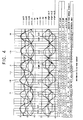
- Figure 4 is a graph showing excitation phase current, current difference, and the classification result of the current difference in correspondence with the angular position of the four-pole motor.
- the angular position has a predetermined characteristic with regard to the magnitude of the excitation phase current within the 30-degree position range of the rotor 12. That is, IU is always greater than -IW within the range of 0 ⁇ 30 degrees, and -IW is always greater than -IU within the range of 30 ⁇ 60 degrees.
- the classification result of the current difference represented by a sign (positive or negative) is divided according to angles, at operation 36.
- the angles are categorized according to the combinations of the signs besides duplication appearing at several angles.
- duplicated angles are distinguished.
- inherent information about the current magnitude or the like for each range is compared.
- the following references shown in ⁇ Table 2> can be applied to distinguish the duplicated angles at 10 degrees, 15 degrees, and 20 degrees.
- three current differences i.e., ⁇ I1, ⁇ I2, and ⁇ I3 may all be limited to small values. This is the case where the current differences are all classified into the "0" range.
- the value of each current difference can be calculated as a predetermined reference value approximately equal to or less than 0. When this condition is satisfied, magnetic resistance is at a minimum value.
- the maximum excitation phase current can be selected as the determination base.
- the maximum excitation phase current is IU at the angle of 0 degrees, but IW is the maximum at the angle of 60 degrees.
- the excitation phase currents detected by the current detector 5 are compared by the inverter controller 7, thereby classifying the rotation angles according to the rotor position.
- the current sum of the current difference between the excitation phase currents is calculated and used.
- the calculated current sum can be classified as a "-1", "0" and "1" range, similar to the current difference.
- the method of detecting the position of the rotor 12 using the current sum can be applied when three current differences are all limited to small values of a predetermined reference range or below, for example, when the current differences are all classified into the "0" range.
- the sum of ⁇ I2 and ⁇ I3 is classified into the "0" range at the angle of 30 degree and the "1" range at the angle of 120 degree.
- the more reliable rotation angle i.e. the position of the rotor 12, can be calculated at the minimum magnetic resistances R1 ⁇ R3.
- a proper control driving signal corresponding to the position of the rotor 12, is transmitted to the inverter 3 on the basis of information about the calculated position of the rotor 12, thereby driving the electric motor.
- the specific synchronization/acceleration drive is performed until the back electromotive force, due to rotation of the rotor 12, reaches or exceeds a predetermined value.
- the number of selectable switching states is six as shown in ⁇ Table 1 >, and the inverter controller 7 excites two phases allowing the rotation of the electric motor to generate maximum torque.
- Figure 6 is a graph showing the excitation phase current with respect to time, wherein the excitation phase current is supplied to the three-phase motor 1 by a pulse width modulation (PWM) driving signal transmitted from the inverter controller 7 to an inverter 3.
- PWM pulse width modulation
- the PWM signal has a period of "T”, an "on-time” of "a” and a “duty ratio” of "a/T".
- the current detected by the current detector 5 has a triangular waveform.
- the previous three triangular waves reach a maximum value that is less than or equal to a first reference value. If the triangular wave "A" reaches a maximum value which is greater than the first reference value, as seen in the fourth triangular wave, the inverter controller 7 applies a driving pulse to the transistors Q1 ⁇ Q6 of the inverter 3, wherein the driving pulse has a period that is half of the period "T" of the PWM driving signal. This keeps the duty ratio constant.
- a first PWM driving signal is transmitted to the transistors Q1 ⁇ Q6 to keep the phase excited in the first period, and a second PWM driving signal is transmitted to the transistors Q1 ⁇ Q6 to be selectively turned on to excite the next phase.
- the inverter controller 7 determines the magnitude of current triangular waves "B" and "C", as detected by the current detector 5 in response to the driving pulse.
- the current "C” is beyond a second reference value, which is greater than the first reference value, the first and second PWM driving signals are repeatedly output in the first and second periods of the next period as the driving signal.
- the inverter controller 7 compares the excitation phase current triangular waves "D" and "E", as detected by the current detector 5. As a result of this comparison, where the detected excitation phase currents are higher than the first reference value and its maximum value has a deviation within a predetermined range, the commutation is performed by the following sequence. On the other hand, if the detected and compared excitation phase currents have a maximum value greater than the predetermined range, the inverter 5 is driven to change into the sequence of the previous triangular wave signals "B" and "C".
- the driving signal is repeatedly input.
- the inverter 3 is controlled so as to operate by the same mode as used to produce the triangular wave signals "D" and "E".
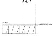
- Figure 7 is a graph showing the excitation phase current with respect to time, wherein the excitation phase current is measured with respect to the driving pulse, which illustrates another commutation method according to the present invention.
- the inverter controller 7 applies a PWM driving signal having a constant duty ratio to the inverter 3.
- the current detected by the current detector 5 has the triangular waveform.
- the inverter controller 7 determines the commutation when the maximum value of the excitation phase current detected by the current detector 5 is greater than the first reference value, and then excites the phases according to the following sequence.
- noise due to continuous driving of the conventional hard switching is decreased to a noise level associated with soft switching.
- the present invention provides an electric motor driving apparatus and an initial driving method, in which correct commutation is performed due to normal rotation so that the electric motor can be driven by a low driving current, thereby reducing both power consumption and noise.
Landscapes
- Engineering & Computer Science (AREA)
- Power Engineering (AREA)
- Control Of Motors That Do Not Use Commutators (AREA)
- Control Of Ac Motors In General (AREA)
- Control Of Stepping Motors (AREA)
- Control Of Multiple Motors (AREA)
Applications Claiming Priority (1)
| Application Number | Priority Date | Filing Date | Title |
|---|---|---|---|
| KR1020040066888A KR100661654B1 (ko) | 2004-08-24 | 2004-08-24 | 모터구동장치 및 3상 모터의 초기 구동방법 |
Publications (2)
| Publication Number | Publication Date |
|---|---|
| EP1630946A2 true EP1630946A2 (de) | 2006-03-01 |
| EP1630946A3 EP1630946A3 (de) | 2009-12-09 |
Family
ID=36093622
Family Applications (1)
| Application Number | Title | Priority Date | Filing Date |
|---|---|---|---|
| EP05103400A Withdrawn EP1630946A3 (de) | 2004-08-24 | 2005-04-26 | Verfahren und Vorrichtung zum Starten eines Motors |
Country Status (5)
| Country | Link |
|---|---|
| US (1) | US7466094B2 (de) |
| EP (1) | EP1630946A3 (de) |
| JP (1) | JP2006067787A (de) |
| KR (1) | KR100661654B1 (de) |
| CN (1) | CN100373763C (de) |
Cited By (1)
| Publication number | Priority date | Publication date | Assignee | Title |
|---|---|---|---|---|
| CN110880898A (zh) * | 2019-11-28 | 2020-03-13 | 北京云迹科技有限公司 | 电机转子初始位置定位方法、装置、电子设备及存储介质 |
Families Citing this family (19)
| Publication number | Priority date | Publication date | Assignee | Title |
|---|---|---|---|---|
| DE102005018526B4 (de) * | 2005-04-20 | 2008-06-12 | Conti Temic Microelectronic Gmbh | Verfahren zur Ermittlung der Position eines Rotors eines Elektromotors |
| DE102007004094A1 (de) * | 2007-01-26 | 2008-08-07 | Siemens Ag | Verfahren und Vorrichtung zur Steuerung einer mittels Pulsweitenmodulation steuerbaren Drehstrommaschine mit mehreren Phasenwicklungen |
| JP4930085B2 (ja) * | 2007-02-08 | 2012-05-09 | 株式会社富士通ゼネラル | 位相検出方法、位相検出装置、同期モータの制御方法、および同期モータの制御装置 |
| FI121616B (fi) * | 2008-04-24 | 2011-01-31 | Kone Corp | Sähkökoneen roottorin asennon määritys |
| CN101729001B (zh) * | 2008-10-16 | 2012-05-30 | 鸿富锦精密工业(深圳)有限公司 | 马达的磁极角定位系统及方法 |
| TWI382650B (zh) * | 2009-01-22 | 2013-01-11 | Richtek Techohnology Corp | 永磁式同步馬達的轉子位置偵測裝置及方法 |
| CN101800509B (zh) * | 2009-02-10 | 2013-09-18 | 立锜科技股份有限公司 | 永磁式同步马达的转子位置检测装置及方法 |
| IL203642A (en) | 2010-02-01 | 2014-01-30 | Yesaiahu Redler | A system and method for optimizing electric current utilization in the control of multiplex motors, and a projectile device containing it |
| DE102010020215A1 (de) * | 2010-05-12 | 2011-11-17 | Andreas Stihl Ag & Co. Kg | Verfahren zum Betrieb eines elektronisch kommutierten Elektromotors sowie Vorrichtung zur Durchführung des Verfahrens |
| KR101285464B1 (ko) * | 2011-06-28 | 2013-07-12 | 주식회사 만도 | 조향각센서 페일 검출 시스템 |
| US9729088B2 (en) | 2013-04-22 | 2017-08-08 | Nxp Usa, Inc. | Method, computer program product and controller for starting-up a switched reluctance motor, and electrical apparatus implementing same |
| DE102015105007A1 (de) * | 2015-03-31 | 2016-10-06 | Ebm-Papst Mulfingen Gmbh & Co. Kg | Verfahren zur sensorlosen Lagebestimmung des Rotors von elektronisch kommutierten Synchronmaschinen |
| US9887589B2 (en) | 2015-08-25 | 2018-02-06 | Ossia Inc. | Systems and methods for improved phase determinations in wireless power delivery environments |
| DE102017127410A1 (de) * | 2016-11-22 | 2018-05-24 | Schaeffler Technologies AG & Co. KG | Verfahren und Schaltungsanordnung zur Ermittlung der Stellung eines Rotors eines Elektromotors |
| US10651690B2 (en) | 2018-05-01 | 2020-05-12 | Ossia Inc. | Wireless transmission in shared wireless medium environments |
| US10743347B2 (en) | 2018-05-29 | 2020-08-11 | Ossia Inc. | Wireless transmission in shared wireless medium environments using multiple PHYs |
| DE102018127412A1 (de) | 2018-11-02 | 2020-05-07 | Elmos Semiconductor Aktiengesellschaft | Verfahren zur sensorlosen Positionsdetektion eines Motors mittels Löschung der magnetischen Vorgeschichte |
| DE102019127051A1 (de) | 2018-11-06 | 2020-05-07 | Elmos Semiconductor Aktiengesellschaft | Verfahren zur geräuschlosen, messpulsfreien Regelung der Kommutierung eines BLDC-Motors im Haltebetrieb |
| CN110535376B (zh) * | 2019-09-25 | 2020-11-27 | 国家电网有限公司 | 一种静止变频器脉冲换相阶段转速控制方法 |
Family Cites Families (29)
| Publication number | Priority date | Publication date | Assignee | Title |
|---|---|---|---|---|
| US4876491A (en) * | 1986-07-01 | 1989-10-24 | Conner Peripherals, Inc. | Method and apparatus for brushless DC motor speed control |
| US4992710A (en) | 1989-09-27 | 1991-02-12 | Seagate Technology, Inc. | Position detection for a brushless DC motor with sample time optimization |
| US5028852A (en) * | 1990-06-21 | 1991-07-02 | Seagate Technology, Inc. | Position detection for a brushless DC motor without hall effect devices using a time differential method |
| US5254914A (en) | 1990-06-29 | 1993-10-19 | Seagate Technology, Inc. | Position detection for a brushless DC motor without Hall effect devices using a mutual inductance detection method |
| US5117165A (en) * | 1990-06-29 | 1992-05-26 | Seagate Technology, Inc. | Closed-loop control of a brushless DC motor from standstill to medium speed |
| IT1253596B (it) | 1991-10-31 | 1995-08-22 | Sgs Thomson Microelectronics | Sistema di avviamento per un motore brushless multifase, privo di sensori di posizione del rotore. |
| US5327053A (en) | 1992-08-12 | 1994-07-05 | Seagate Technology, Inc. | Apparatus and method for detecting rotor position in a sensorless and brushless DC motor |
| WO1994011945A1 (en) * | 1992-11-06 | 1994-05-26 | Georgia Tech Research Corporation | Method of observer-based control of permanent-magnet synchronous motors |
| JP3381408B2 (ja) * | 1993-10-26 | 2003-02-24 | トヨタ自動車株式会社 | 電気角検出装置およびこれを用いた同期モータの駆動装置 |
| US5701065A (en) * | 1993-11-18 | 1997-12-23 | Ishizaki; Akira | Method and apparatus for controlling synchronous motor |
| US5537020A (en) * | 1994-12-28 | 1996-07-16 | Hydro-Quebec | Method and apparatus for starting up a synchronous machine |
| US5569990A (en) | 1995-03-31 | 1996-10-29 | Seagate Technology, Inc. | Detection of starting motor position in a brushless DC motor |
| US5841252A (en) | 1995-03-31 | 1998-11-24 | Seagate Technology, Inc. | Detection of starting motor position in a brushless DC motor |
| JP3381509B2 (ja) * | 1996-02-29 | 2003-03-04 | トヨタ自動車株式会社 | 電気角検出装置および同期モータの駆動装置 |
| JPH10254550A (ja) * | 1997-03-12 | 1998-09-25 | Yaskawa Electric Corp | 位置制御装置 |
| JP3282657B2 (ja) * | 1997-06-18 | 2002-05-20 | 株式会社安川電機 | 永久磁石形ブラシレスモータの初期磁極位置推定方法 |
| AUPP208798A0 (en) * | 1998-03-02 | 1998-03-26 | Casttikulm Research Pty Ltd | Motor controller |
| JP2000023498A (ja) | 1998-07-03 | 2000-01-21 | Yaskawa Electric Corp | Ipmモータの制御方法及び制御装置 |
| US6100656A (en) | 1999-01-19 | 2000-08-08 | Quantum Corporation | Start-up algorithm for a brushless sensorless motor |
| KR100327862B1 (ko) * | 2000-01-19 | 2002-03-09 | 이준식 | 인덕턴스의 변화를 이용한 브러시리스 직류 모터의 초기위치 판별 및 초기 구동 알고리즘 |
| JP3681318B2 (ja) * | 2000-02-28 | 2005-08-10 | 株式会社日立製作所 | 同期モータ制御装置及びそれを用いた車両 |
| JP2002238275A (ja) * | 2001-02-07 | 2002-08-23 | Toshiba Corp | Pwmインバータ装置 |
| JP2002272175A (ja) * | 2001-03-08 | 2002-09-20 | Sumitomo Heavy Ind Ltd | モータの初期位相検出方式、検出方法、及び、制御器 |
| JP4075338B2 (ja) * | 2001-07-18 | 2008-04-16 | 株式会社豊田自動織機 | 電動圧縮機の制御方法 |
| US6791293B2 (en) * | 2001-08-27 | 2004-09-14 | Mitsubishi Denki Kabushiki Kaisha | Sensorless control device for synchronous electric motor |
| JP2003209989A (ja) | 2002-01-10 | 2003-07-25 | Toshiba Corp | ブラシレスdcモータの回転位置検出方法および回転位置検出装置並びに冷蔵庫 |
| JP4944606B2 (ja) * | 2004-05-24 | 2012-06-06 | ローム株式会社 | 回転制御装置及び方法、及びその回転制御装置を利用可能な電子機器 |
| JP4581544B2 (ja) * | 2004-08-02 | 2010-11-17 | 国産電機株式会社 | 回転電機の回転子位置判定方法、回転子位置判定装置及び回転電機の制御装置 |
| US7334854B1 (en) * | 2006-09-20 | 2008-02-26 | Aimtron Technology Corp. | Sensorless start-up method for driving a brushless DC motor |
-
2004
- 2004-08-24 KR KR1020040066888A patent/KR100661654B1/ko not_active Expired - Fee Related
-
2005
- 2005-04-26 EP EP05103400A patent/EP1630946A3/de not_active Withdrawn
- 2005-05-31 CN CNB2005100740882A patent/CN100373763C/zh not_active Expired - Fee Related
- 2005-08-23 JP JP2005241548A patent/JP2006067787A/ja active Pending
- 2005-08-24 US US11/209,654 patent/US7466094B2/en not_active Expired - Fee Related
Cited By (1)
| Publication number | Priority date | Publication date | Assignee | Title |
|---|---|---|---|---|
| CN110880898A (zh) * | 2019-11-28 | 2020-03-13 | 北京云迹科技有限公司 | 电机转子初始位置定位方法、装置、电子设备及存储介质 |
Also Published As
| Publication number | Publication date |
|---|---|
| US20060043915A1 (en) | 2006-03-02 |
| KR100661654B1 (ko) | 2006-12-26 |
| EP1630946A3 (de) | 2009-12-09 |
| CN1741366A (zh) | 2006-03-01 |
| KR20060018499A (ko) | 2006-03-02 |
| JP2006067787A (ja) | 2006-03-09 |
| CN100373763C (zh) | 2008-03-05 |
| US7466094B2 (en) | 2008-12-16 |
Similar Documents
| Publication | Publication Date | Title |
|---|---|---|
| EP1630946A2 (de) | Verfahren und Vorrichtung zum Starten eines Motors | |
| CN100525062C (zh) | 无传感器无刷电动机及其控制电路和控制方法 | |
| US7598698B2 (en) | Motor control device | |
| US6995530B2 (en) | System, method, and an article of manufacture for starting a brushless direct current motor | |
| EP2689529B1 (de) | Verfahren und vorrichtung zum ansteuern einer elektrischen maschine | |
| US6661192B2 (en) | Controlling a brushless DC motor | |
| CN103780171B (zh) | 用于在低速或零速下的无传感器永磁无刷电机的不同类型操作之间切换以决定转子位置的方法及系统 | |
| CN101095279A (zh) | 无刷直流电动机的控制 | |
| EP1482632A2 (de) | Steuerung eines bürstenlosen Gleichstrommotors | |
| EP1739822A1 (de) | Reglung für einen drei Phasen bürstenlosen Gleichstrommotor und entsprechendes Regelverfahren | |
| EP1575158B1 (de) | Positionsbestimmung des Rotors eines bürstenlosen Gleichstrommotors | |
| US11616459B2 (en) | Drive methods for a three-phase motor | |
| EP1635447A2 (de) | Drehstrommotorsteuergerät | |
| JP4110883B2 (ja) | モータ制御装置 | |
| JP2005328635A (ja) | スイッチトリラクタンスモータの制御装置 | |
| JP3309828B2 (ja) | モータ駆動制御装置 | |
| KR101804464B1 (ko) | Bldc 모터 제어 장치 및 그 방법 | |
| US20240128903A1 (en) | Method of controlling a three-phase permanent-magnet motor | |
| CN114287105B (zh) | 用于启动无传感器单相电动机的方法和无传感器单相电动机 | |
| JP4003700B2 (ja) | 6線式3相ブラシレスモータ制御装置 | |
| KR20250002629A (ko) | 브러시리스 영구 자석 모터를 제어하는 방법 | |
| JP2000014187A (ja) | 直流ブラシレスモータ駆動装置とこれを用いたルームエアコン | |
| JP2004343912A (ja) | モータ制御装置 |
Legal Events
| Date | Code | Title | Description |
|---|---|---|---|
| PUAI | Public reference made under article 153(3) epc to a published international application that has entered the european phase |
Free format text: ORIGINAL CODE: 0009012 |
|
| AK | Designated contracting states |
Kind code of ref document: A2 Designated state(s): AT BE BG CH CY CZ DE DK EE ES FI FR GB GR HU IE IS IT LI LT LU MC NL PL PT RO SE SI SK TR |
|
| AX | Request for extension of the european patent |
Extension state: AL BA HR LV MK YU |
|
| PUAL | Search report despatched |
Free format text: ORIGINAL CODE: 0009013 |
|
| AK | Designated contracting states |
Kind code of ref document: A3 Designated state(s): AT BE BG CH CY CZ DE DK EE ES FI FR GB GR HU IE IS IT LI LT LU MC NL PL PT RO SE SI SK TR |
|
| AX | Request for extension of the european patent |
Extension state: AL BA HR LV MK YU |
|
| RIC1 | Information provided on ipc code assigned before grant |
Ipc: H02P 6/18 20060101ALI20091103BHEP Ipc: H02P 6/20 20060101AFI20051220BHEP |
|
| STAA | Information on the status of an ep patent application or granted ep patent |
Free format text: STATUS: THE APPLICATION IS DEEMED TO BE WITHDRAWN |
|
| 18D | Application deemed to be withdrawn |
Effective date: 20091103 |