EP1630835B1 - Kontakt für einen Fahrzeugshornstromkreis - Google Patents
Kontakt für einen Fahrzeugshornstromkreis Download PDFInfo
- Publication number
- EP1630835B1 EP1630835B1 EP05107697A EP05107697A EP1630835B1 EP 1630835 B1 EP1630835 B1 EP 1630835B1 EP 05107697 A EP05107697 A EP 05107697A EP 05107697 A EP05107697 A EP 05107697A EP 1630835 B1 EP1630835 B1 EP 1630835B1
- Authority
- EP
- European Patent Office
- Prior art keywords
- prong
- steering wheel
- carbon
- contact
- conductive portion
- Prior art date
- Legal status (The legal status is an assumption and is not a legal conclusion. Google has not performed a legal analysis and makes no representation as to the accuracy of the status listed.)
- Expired - Lifetime
Links
Images


Classifications
-
- B—PERFORMING OPERATIONS; TRANSPORTING
- B60—VEHICLES IN GENERAL
- B60Q—ARRANGEMENT OF SIGNALLING OR LIGHTING DEVICES, THE MOUNTING OR SUPPORTING THEREOF OR CIRCUITS THEREFOR, FOR VEHICLES IN GENERAL
- B60Q5/00—Arrangement or adaptation of acoustic signal devices
- B60Q5/001—Switches therefor
- B60Q5/003—Switches therefor mounted on the steering wheel
-
- H—ELECTRICITY
- H01—ELECTRIC ELEMENTS
- H01H—ELECTRIC SWITCHES; RELAYS; SELECTORS; EMERGENCY PROTECTIVE DEVICES
- H01H1/00—Contacts
- H01H1/58—Electric connections to or between contacts; Terminals
- H01H1/5833—Electric connections to or between contacts; Terminals comprising an articulating, sliding or rolling contact between movable contact and terminal
Definitions
- the invention relates generally to components of an electrical circuit such as those used with a vehicle horn. More specifically, the invention related to an electrical contact with improved wear and operating life characteristics.
- Horns are used in all types of vehicles. A horn is particularly important in a forklift truck because of the significant dangers surrounding the use of forklift trucks. For example, many forklift trucks have structures that obscure the driver's view, making it difficult for the driver to see pedestrians in the path of the forklift truck. In addition, many forklift trucks are operated in a warehouse, where a pedestrian could walk around a blind corner and into the path of a forklift truck. In such a case, neither the pedestrian nor the forklift truck operator is able to see the other in time to prevent an accident. Additionally, forklift trucks are often used to carry heavy loads that could fall and cause severe injuries in an accident.
- a horn is an important safety device on a forklift truck because it enables the operator to warn people nearby to stay clear of the forklift truck. Because of the important safety aspects, the horn in a forklift truck is used much more often than a horn in a typical passenger car. In many cases, the horn on a forklift truck is used more than one million times during the life of the forklift truck.
- horns including horns on forklift trucks, are activated by depressing the center of a steering wheel. When the center section of the steering wheel is depressed, it makes electrical contact to complete the horn circuit.
- the primary difficulty in completing a horn circuit is that it must be done in a way that will still enable the rotation of the steering wheel to steer the vehicle.
- FIG. 1 shows a steering wheel assembly 100 that includes a steering wheel 101 connected to a steering column 105.
- the steering column 105 connects to the steering wheel 101 just above a base or a control assembly 107.
- the steering wheel 101 includes a center section 104 that may be depressed to energize a horn circuit (not shown).
- FIG. 2 is an view of the underside of the steering wheel 101.
- the steering wheel 101 includes a socket 204 for connecting to a steering column ( e.g ., column 105 in FIG. 1 ).
- the steering wheel 101 also includes a conductive portion 202.
- the conductive portion 202 is attached to the underside of the steering wheel 101, and in other embodiments, the conductive portion 202 may be integral to the steering wheel 101.
- FIG. 3 is a cross section of a steering wheel 101 with a conductive portion 202 located on the underside of the steering wheel 101 .
- the steering wheel 10 1 is connected to a steering column 105.
- a control assembly 107 is positioned below the steering wheel 101.
- a conductive prong 301 extends from the control assembly 107, and the prong 301 is coupled to the control assembly 107 (e.g., with bolt 308 or other suitable means).
- the prong 301 extends to be in electrical contact with the conductive portion 202 on the steering wheel 101.
- the prong 301 maintains electrical contact with the conductive portion 202.
- the conductive portion 202 is electrically connected to the center section 104 of the steering wheel 101.
- the circuit is closed, and an electrical connection is created between the conductive portion 202 and the steering column 105, by way of the center section 104 of the steering wheel 101.
- the base of the prong 301 is electrically connected to the horn circuit, and the steering column 105 is electrically connected to ground.
- the prong 301 includes a protrusion 305 at the end of the prong 301 1 for making electrical contact with the conductive portion 202 of the steering wheel 101. It is noted that different shapes and geometries on the end of a prong may be used. The shape of the contact point on the prong in not important to the operation of the circuit.
- Wear-induced horn failure is considered a normal limitation of a horn circuit lifespan and a worn contact is often the cause.
- a worn prong or brush head is effective in most cases, in certain applications even short-lived vehicular horn failure may pose an unacceptably high safety hazard.
- United States patent US 4, 380, 341 discloses a sliding contact device for a steering column of a vehicle wherein carbon brushes 14 are mounted on springs 13 and pushed thereby against conductive parts, i.e., slip ring pairs of the steering wheel.
- the invention provides a horn circuit and a method for manufacturing a vehicular horn system as described in the appended independent and dependent claims.
- FIG. 1 shows a perspective view of a steering wheel.
- FIG. 2 shows a perspective view of the underside of a steering wheel.
- FIG.3 shows a prior art horn circuit.
- FIG. 4 shows a horn circuit in accordance with one embodiment of the invention.
- FIG. 5 shows a carbon-based contact in accordance with one embodiment of the invention.
- FIG. 6 shows a horn circuit in accordance with one embodiment of the invention.
- FIG. 7A shows a circuit diagram of a horn circuit in accordance with one embodiment of the invention.
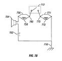
- FIG. 7B shows a circuit diagram of a horn circuit in accordance with another embodiment of the invention.
- the invention comprises a wear-resistant contact for a vehicular horn circuit.
- embodiments of the invention use carbon-based compounds as a contact for a vehicular horn circuit.
- carbon-based is used to mean a compresses hardened carbon based solid.
- connection is used to mean joined or fastened together. It may mean that two or more things are directly connected to each other, and it may also include things that are indirectly connected. Thus, two things may be connected even when there is an intervening structure.
- Electrically connected is used to mean that electricity can flow between two things that are electrically connected. Other circuit elements may or may not be connected between items that are electrically connected, so long as electricity may flow between the electrically connected items.
- FIG. 4 shows a partial horn circuit 400 in accordance with one embodiment of the invention.
- the steering wheel 101 is connected to a steering column 105 that is used to steer the vehicle (e.g., a forklift truck).
- the horn circuit 400 is connected through the steering wheel 101 so that depressing the center section 104 of the steering wheel 101 will close the horn circuit.
- the steering wheel 101 includes a conductive portion 202 located on the underside of the steering wheel 101. Electrical contact is made between the conductive portion 202 and a prong 401 that extends from the control assembly 107 to the steering wheel 101. A carbon-based contact 402 is positioned at the end of the prong 401 so that it makes electrical contact with the conductive portion 202 on the underside of the steering wheel 101. Because the conductive portion 202 in this embodiment encircles the bottom of the steering wheel 101, the carbon-based contact 402 will maintain electrical contact with the conductive portion 202, even when the steering wheel 101 is rotated to steer the vehicle.
- carbon-based contacts include, for example, a material such as CTI-22, typically compressed to a hardness in the 40-43C range on the Rockwell scale.
- the prong 401 is connected to the control assembly 107. It is noted that some embodiments may not include a control assembly.
- the prong 401 may be connected by any means known in the art.
- FIG. 4 shows the prong 401 coupled to the control assembly 107 by a bolt 408.
- the prong may be soldered, riveted, or connected by other means.
- a prong may be connected to any structure, generically called a "base,” that will support the prong and hold it in place.
- the prong 401 is electrically connected in the horn circuit at the base of the prong 401. That is, the electrical current flows through the prong 401 and the carbon-based contact 402, when the horn circuit is closed.
- a wire lead 411 is connected to the carbon-based contact 402, and the wire lead 411 forms part of the horn circuit.
- a wire lead 411 and the prong 401 are connected essentially in parallel so that both the prong 401 and the wire lead 411 form part of the horn circuit.
- the partial circuit shown in FIG. 4 includes only one conductive portion 202 and prong 401.
- the horn circuit may be completed through the steering column 105, which may be grounded to the negative terminal of the battery (not shown) in the vehicle.
- the electrical current flows through the prong 401, through the carbon-based contact 402, and into the steering wheel 101 through the conductive portion 202.
- the current then flows through the center section 104 of the steering wheel 101, when depressed, and through the steering column 105.
- the invention is not limited by the direction of electrical current flow.
- the prong 401 may be electrically connected to the ground ( i.e., negative terminal of the battery), and the steering column 105 is electrically connected to the positive terminal of a battery (not shown).
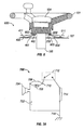
- FIG. 5 shows an enlarged view of a prong 401 and a carbon-based contact 402, in accordance with one embodiment of the invention.
- the carbon-based contact 402 is positioned at the end of the prong 401.
- the carbon-based contact 402 is connected to an electrical lead 411 that electrically connects the carbon-based contact 402 to the horn circuit.
- the carbon-based contact 402 is coupled to the horn circuit by the prong 401.
- the carbon-based contact 402 is substantially cylindrical.
- a carbon-based contact 402 has a substantially flat upper surface for maximizing the surface area in contact with the conductive portion 202.
- FIG. 6 shows an embodiment of a partial horn circuit 600 in accordance with another embodiment of the invention.
- the steering wheel 101 includes a first conductive portion 202 and a second conductive portion 602.
- the circuit 600 includes a prong 401 with a carbon-based contact 402 that is in electrical contact with the first conductive portion 202 on the underside of the steering wheel 101.
- the carbon based-contact 402 may include an electrical lead 411 that connects the carbon-based contact 402 to the remainder of the horn circuit 600.
- the circuit also includes a second prong 604 that is coupled to the control assembly 107.
- the second prong 604 includes a second carbon-based contact 603 that is in electrical contact with the second conductive portion 602 on the underside of the steering wheel 101. Again, because the second conductive portion 602 is circular, the second carbon-based contact 603 remains in electrical contact with the second conductive portion 602 even when the steering wheel 101 is rotated.
- the steering wheel 101 need not be grounded.
- the steering wheel 101 includes two conductive portions 202, 602 that are in electrical contact with two carbon-based contacts 402, 603 and prongs 401, 604, respectively.
- the positive connection may be made through one of the prong-contact-ring connections, and the negative (or ground) connection may be made through the other.
- FIG. 7A shows a circuit diagram for one embodiment of a horn circuit 700 in accordance with the invention.
- a horn 704 is electrically connected to a battery 702 that supplies electrical power to the horn 704.
- the horn 704 is also electrically connected to a switch 712 that enables activation of the horn 704.
- the switch 712 may be the center section of a steering wheel that will complete the circuit 700 when it is depressed.
- a prong 708 is shown between the horn 704 and the switch 712. In some embodiments, the prong 708 is electrically connected to both the horn 704 and the switch 712.
- a carbon-based contact 710 is shown as a node between the prong 708 and the switch 712. As described above, in some embodiments, a carbon-based contact is positioned at the end of the prong and is in electrical contact with a conductive portion on the steering wheel. The conductive portion is electrically connected to the switch 714 in the center section of the steering wheel (e.g., 104 in FIG. 4 ).
- Some embodiments include a wire lead 706 that is electrically connected between the horn 704 and the carbon-based contact 710.
- a wire lead 706 may be used with a non-conductive prong (a non-conductive prong would not appear on a circuit diagram).
- the wire lead 706 and a conductive prong 708 may be electrically connected in parallel.
- the section designated at 714 represents a steering column that is electrically connected between the switch 712 and the chassis ground 716.
- the chassis ground 716 is electrically connected to the negative terminal of the battery 702 to complete the circuit 700.
- FIG. 7B shows another embodiment of a horn circuit 750 in accordance with the invention.
- a battery 702 is electrically connected to a horn 704, and the horn is electrically connected to a switch 712 by a prong 758 and/or a wire lead 756.
- a carbon-based contact 760 is electrically connected to the prong 758 and the wire lead 756, and the carbon-based contact 760 is in electrical contact with a conductive portion on the steering wheel (not shown).
- the conductive portion is electrically connected to the switch 712.
- the circuit 750 does not include a steering column, as in FIG. 7A .
- a a second carbon-based contact 770 is in electrical contact with a second conductive portion (not shown).
- a second prong 772 and/or a second wire lead 771 are electrically connected to the chassis ground 716, which may be electrically connected to the negative terminal of the battery 702.
- the wire leads 756, 771 may be used in parallel with the prongs 758, 772, or they may be used independently of the prongs 758,772. Additionally, some embodiments may not include wire leads 756, 771.
- a carbon-based contact may comprise any carbon-based compound or carbon graphite compound known in the art.
- the carbon based contact may comprise a CTI-22 type carbon compound, available from Morgan AM&T (St. Marys, PA).
- a carbon-based contact in accordance is not limited to a cylindrical shape.
- a carbon-based contact may comprise a brush as known in the art. Other shapes are possible.
- Embodiments of the invention may present one or more of the following advantages.
- a carbon-based contact may enable a larger surface area to be in contact with a conductive portion on a steering wheel.
- the larger surface area will enable better electrical contact.
- the larger surface area will decrease the tendency of the contact to gall, gauge, or score the steering wheel or conductive portion, thereby increasing the operating life of the horn circuit.
- the embodiment described refer to certain geometries for various components, those having ordinary skill in the art will appreciate that other geometries may be used without departing from the scope of the invention.
- a carbon-based contact will not wear as easily as other materials, thus increasing the life of a horn circuit.
- the carbon-based contact may also provide a lower coefficient of friction with a steering wheel or a conductive portion. This will decrease the tendency of the contact to wear from the friction with the steering wheel or conductive portion.
Landscapes
- Physics & Mathematics (AREA)
- Acoustics & Sound (AREA)
- Engineering & Computer Science (AREA)
- Mechanical Engineering (AREA)
- Steering Controls (AREA)
- Push-Button Switches (AREA)
- Control And Other Processes For Unpacking Of Materials (AREA)
Claims (10)
- Hupenstromkreis für ein Fahrzeug, wobei der Hupenstromkreis umfasst:ein Lenkrad (101), das in Bezug auf eine Basis (107) drehbar ist;wobei der Hupenstromkreis dadurch gekennzeichnet ist, dass er ferner umfasst:einen Anschlussstift (401), der von der Basis (107) ausgeht, wobei der Anschlussstift ein erstes Ende, das starr an der Basis befestigt ist, und ein zweites, freies Ende enthält; undeinen Kontakt (402) auf Kohlenstoffgrundlage, der an dem zweiten, freien Ende des Anschlussstifts angeordnet ist, wobei der Stift auf Kohlenstoffgrundlage selbst dann mit einem leitenden Abschnitt (202) des Lenkrads in elektrischem Kontakt steht, wenn das Lenkrad (101) gedreht wird.
- Hupenstromkreis nach Anspruch 1, bei dem der Kontakt auf Kohlenstoffgrundlage im Wesentlichen zylindrisch ist.
- Hupenstromkreis nach Anspruch 1, der ferner eine elektrische Leitung (411) umfasst, die mit dem Kontakt auf Kohlenstoffgrundlage elektrisch verbunden ist und mit dem Hupenstromkreis elektrisch verbunden ist.
- Hupenstromkreis nach Anspruch 1, bei dem die Basis eine Steuerbaueinheit (107) umfasst.
- Hupenstromkreis nach Anspruch 1, der ferner einen Mittelabschnitt (104) des Lenkrads umfasst, der so konfiguriert ist, dass er den Hupenstromkreis schließt, wenn der Mittelabschnitt niedergedrückt wird.
- Hupenstromkreis nach Anspruch 1, der ferner einen zweiten Anschlussstift (604), der von der Basis (107) ausgeht, und einen zweiten Kontakt (603) auf Kohlenstoffgrundlage, der an einem Ende des zweiten Anschlussstifts positioniert ist, umfasst, wobei der zweite Kontakt auf Kohlenstoffgrundlage mit einem zweiten leitenden Abschnitt (602) des Lenkrads in elektrischem Kontakt steht.
- Verfahren zur Herstellung eines Fahrzeughupensystems, wobei das Verfahren Folgendes umfasst:Verbinden eines Lenkrads mit einer Lenksäule, die durch eine Basis verläuft, wobei das Lenkrad in Bezug auf die Basis (107) drehbar ist;wobei das Verfahren dadurch gekennzeichnet ist, dass es ferner Folgendes umfasst:Verbinden eines Anschlussstifts mit der Basis, wobei der Anschlussstift ein erstes Ende, das starr an der Basis befestigt ist, und ein zweites, freies Ende enthält; undPositionieren eines Kontakts auf Kohlenstoffgrundlage an dem zweiten, freien Ende des Anschlussstifts in der Weise, dass er mit dem Lenkrad in elektrischem Kontakt steht.
- Verfahren nach Anspruch 7, das ferner das Positionieren eines leitenden Abschnitts auf einer Unterseite des Lenkrads umfasst, wobei der Kontakt auf Kohlenstoffgrundlage so positioniert wird, dass er mit dem leitenden Abschnitt in elektrischem Kontakt ist.
- Verfahren nach Anspruch 8, das ferner umfasst:Positionieren eines zweiten leitenden Abschnitts auf der Unterseite des Lenkrads;Verbinden eines zweiten Anschlussstifts mit der Basis;Positionieren eines zweiten Kontakts auf Kohlenstoffgrundlage an einem Ende des zweiten Anschlussstifts in der Weise, dass er mit dem zweiten leitenden Abschnitt in elektrischem Kontakt steht.
- Hupenstromkreis nach Anspruch 1, bei dem der Anschlussstift elektrisch leitend ist und über den Anschlussstift, über den Kontakt auf Kohlenstoffgrundlage und über den leitenden Abschnitt des Lenkrads elektrisch leitet, wenn der Hupenstromkreis geschlossen ist.
Applications Claiming Priority (1)
| Application Number | Priority Date | Filing Date | Title |
|---|---|---|---|
| US10/924,638 US7060919B2 (en) | 2004-08-24 | 2004-08-24 | Contact for a vehicle horn circuit |
Publications (2)
| Publication Number | Publication Date |
|---|---|
| EP1630835A1 EP1630835A1 (de) | 2006-03-01 |
| EP1630835B1 true EP1630835B1 (de) | 2008-03-12 |
Family
ID=35134257
Family Applications (1)
| Application Number | Title | Priority Date | Filing Date |
|---|---|---|---|
| EP05107697A Expired - Lifetime EP1630835B1 (de) | 2004-08-24 | 2005-08-22 | Kontakt für einen Fahrzeugshornstromkreis |
Country Status (5)
| Country | Link |
|---|---|
| US (1) | US7060919B2 (de) |
| EP (1) | EP1630835B1 (de) |
| AT (1) | ATE389234T1 (de) |
| CA (1) | CA2516607A1 (de) |
| DE (1) | DE602005005261D1 (de) |
Families Citing this family (1)
| Publication number | Priority date | Publication date | Assignee | Title |
|---|---|---|---|---|
| CN101961991A (zh) * | 2009-07-23 | 2011-02-02 | 广州市白云清洁用品有限公司 | 洗地车旋转双导电喇叭装置 |
Family Cites Families (18)
| Publication number | Priority date | Publication date | Assignee | Title |
|---|---|---|---|---|
| US3127191A (en) * | 1964-03-31 | Periscopic rear view apparatus for vehicles | ||
| FR644660A (fr) | 1927-02-05 | 1928-10-12 | Appareil avertisseur acoustique pour véhicules automobiles | |
| US1988796A (en) * | 1930-11-17 | 1935-01-22 | Trico Products Corp | Horn system |
| US2758289A (en) * | 1951-10-13 | 1956-08-07 | Chrysler Corp | Electrically conductive flexible shaft coupling |
| US2894090A (en) * | 1957-09-26 | 1959-07-07 | Gen Motors Corp | Horn blowing mechanism |
| JPS51152744U (de) * | 1975-05-29 | 1976-12-06 | ||
| MX142898A (es) * | 1975-11-04 | 1981-01-14 | Schmidt Gmbh Karl | Mejoras en instalacion de sanalamiento en los volantes de vehiculos automotrices |
| US4157854A (en) * | 1978-04-21 | 1979-06-12 | General Motors Corporation | Steering column electrical connector arrangement |
| DE3108757C2 (de) * | 1981-03-07 | 1984-08-16 | Daimler-Benz Ag, 7000 Stuttgart | Schleifringanordnung für Lenkhandräder von Kraftwagen |
| US4516001A (en) * | 1983-05-26 | 1985-05-07 | West Frank M | Automobile horn circuit and replacement part therefor |
| DE8606854U1 (de) | 1985-03-12 | 1986-06-12 | Fiat Auto S.P.A., Turin/Torino | Schleifkontakt-Einrichtung für die Lenksäule eines Kraftfahrzeuges |
| DE4131533A1 (de) | 1991-09-21 | 1993-03-25 | Fichtel & Sachs Ag | Lenkwinkelsensor fuer kraftfahrzeuge |
| US5789827A (en) * | 1993-05-10 | 1998-08-04 | Sensitron, Inc. | Two-wire interface to automobile horn relay circuit |
| US5563354A (en) * | 1995-04-03 | 1996-10-08 | Force Imaging Technologies, Inc. | Large area sensing cell |
| DE19908385C2 (de) * | 1999-02-26 | 2001-11-15 | Petri Ag | Kontaktprofil für die Hornauslösung |
| US6576855B2 (en) * | 2001-02-02 | 2003-06-10 | Cole Hersee Co. | Rocker switch |
| US6595306B2 (en) * | 2001-08-09 | 2003-07-22 | Crown Equipment Corporation | Supplemental walk along control for walkie/rider pallet trucks |
| JP2005032556A (ja) * | 2003-07-14 | 2005-02-03 | Alps Electric Co Ltd | スイッチ装置 |
-
2004
- 2004-08-24 US US10/924,638 patent/US7060919B2/en not_active Expired - Fee Related
-
2005
- 2005-08-22 EP EP05107697A patent/EP1630835B1/de not_active Expired - Lifetime
- 2005-08-22 DE DE602005005261T patent/DE602005005261D1/de not_active Expired - Lifetime
- 2005-08-22 AT AT05107697T patent/ATE389234T1/de not_active IP Right Cessation
- 2005-08-23 CA CA002516607A patent/CA2516607A1/en not_active Abandoned
Also Published As
| Publication number | Publication date |
|---|---|
| US7060919B2 (en) | 2006-06-13 |
| EP1630835A1 (de) | 2006-03-01 |
| CA2516607A1 (en) | 2006-02-24 |
| ATE389234T1 (de) | 2008-03-15 |
| US20060042917A1 (en) | 2006-03-02 |
| DE602005005261D1 (de) | 2008-04-24 |
Similar Documents
| Publication | Publication Date | Title |
|---|---|---|
| US6299201B1 (en) | Steering wheel | |
| US6600114B2 (en) | Steering wheel horn switch | |
| US6478330B2 (en) | Steering wheel | |
| JP7209953B2 (ja) | ステアリングホイール | |
| US6491319B2 (en) | Steering wheel assembly and a switching device thereof | |
| US8491003B2 (en) | Airbag frame apparatus | |
| EP1348595A2 (de) | Hupenschaltervorrichtung für Airbagmodul und diese enthaltendes Lenkrad | |
| US10513422B2 (en) | Vehicle jack and adapter therefor | |
| US8939466B2 (en) | Airbag frame apparatus | |
| KR102394806B1 (ko) | 자동차의 혼 작동 장치 | |
| US20050156477A1 (en) | Integrated brush-holder retention system | |
| US7060919B2 (en) | Contact for a vehicle horn circuit | |
| EP0945976A3 (de) | Elektrischer Schaltkreis | |
| US7397004B2 (en) | Push-switch for vehicle and method of manufacturing the same | |
| EP1149730A3 (de) | Schaltereinheit für ein Kraftfahrzeuglenkrad | |
| JP3175621B2 (ja) | エアバッグ装置付きステアリングホイール | |
| JP4196080B2 (ja) | 車両用プッシュスイッチ | |
| JP2008147162A (ja) | 車両用スイッチ | |
| US11884103B2 (en) | Spring support device and vehicle having the same | |
| JP2000052903A (ja) | エアバッグ装置付きステアリングホイ―ル | |
| KR100462728B1 (ko) | 자동차용 러기지램프의 접지 터미널 구조 | |
| JPS63184568A (ja) | 車両用ハンドルスイツチ | |
| JPH0740430Y2 (ja) | 車両用ハンドル部の電気接続子の構造 | |
| KR200184905Y1 (ko) | 지게차의 경음기 스위치 장치 | |
| EP1375260A2 (de) | Fahrzeugschalter |
Legal Events
| Date | Code | Title | Description |
|---|---|---|---|
| PUAI | Public reference made under article 153(3) epc to a published international application that has entered the european phase |
Free format text: ORIGINAL CODE: 0009012 |
|
| AK | Designated contracting states |
Kind code of ref document: A1 Designated state(s): AT BE BG CH CY CZ DE DK EE ES FI FR GB GR HU IE IS IT LI LT LU LV MC NL PL PT RO SE SI SK TR |
|
| AX | Request for extension of the european patent |
Extension state: AL BA HR MK YU |
|
| RIN1 | Information on inventor provided before grant (corrected) |
Inventor name: WINGEROTH, RANDALL L. Inventor name: STOTTS, JAY B. Inventor name: FUSSELL, WILLIAM D. Inventor name: BELL, ROGER L. |
|
| RIN1 | Information on inventor provided before grant (corrected) |
Inventor name: STOTTS, JAY B. Inventor name: FUSSELL, WILLIAM D. Inventor name: BELL, ROGER L. Inventor name: WINGENROTH, RANDALL L. |
|
| 17P | Request for examination filed |
Effective date: 20060817 |
|
| 17Q | First examination report despatched |
Effective date: 20060921 |
|
| AKX | Designation fees paid |
Designated state(s): AT BE BG CH CY CZ DE DK EE ES FI FR GB GR HU IE IS IT LI LT LU LV MC NL PL PT RO SE SI SK TR |
|
| AXX | Extension fees paid |
Extension state: AL Payment date: 20060817 Extension state: YU Payment date: 20060817 Extension state: MK Payment date: 20060817 Extension state: BA Payment date: 20060817 |
|
| GRAP | Despatch of communication of intention to grant a patent |
Free format text: ORIGINAL CODE: EPIDOSNIGR1 |
|
| GRAS | Grant fee paid |
Free format text: ORIGINAL CODE: EPIDOSNIGR3 |
|
| GRAA | (expected) grant |
Free format text: ORIGINAL CODE: 0009210 |
|
| AK | Designated contracting states |
Kind code of ref document: B1 Designated state(s): AT BE BG CH CY CZ DE DK EE ES FI FR GB GR HU IE IS IT LI LT LU LV MC NL PL PT RO SE SI SK TR |
|
| AX | Request for extension of the european patent |
Extension state: AL BA MK YU |
|
| REG | Reference to a national code |
Ref country code: GB Ref legal event code: FG4D |
|
| REG | Reference to a national code |
Ref country code: CH Ref legal event code: EP |
|
| REG | Reference to a national code |
Ref country code: IE Ref legal event code: FG4D |
|
| REF | Corresponds to: |
Ref document number: 602005005261 Country of ref document: DE Date of ref document: 20080424 Kind code of ref document: P |
|
| PG25 | Lapsed in a contracting state [announced via postgrant information from national office to epo] |
Ref country code: FI Free format text: LAPSE BECAUSE OF FAILURE TO SUBMIT A TRANSLATION OF THE DESCRIPTION OR TO PAY THE FEE WITHIN THE PRESCRIBED TIME-LIMIT Effective date: 20080312 Ref country code: LT Free format text: LAPSE BECAUSE OF FAILURE TO SUBMIT A TRANSLATION OF THE DESCRIPTION OR TO PAY THE FEE WITHIN THE PRESCRIBED TIME-LIMIT Effective date: 20080312 |
|
| PG25 | Lapsed in a contracting state [announced via postgrant information from national office to epo] |
Ref country code: AT Free format text: LAPSE BECAUSE OF FAILURE TO SUBMIT A TRANSLATION OF THE DESCRIPTION OR TO PAY THE FEE WITHIN THE PRESCRIBED TIME-LIMIT Effective date: 20080312 |
|
| PG25 | Lapsed in a contracting state [announced via postgrant information from national office to epo] |
Ref country code: LV Free format text: LAPSE BECAUSE OF FAILURE TO SUBMIT A TRANSLATION OF THE DESCRIPTION OR TO PAY THE FEE WITHIN THE PRESCRIBED TIME-LIMIT Effective date: 20080312 Ref country code: SI Free format text: LAPSE BECAUSE OF FAILURE TO SUBMIT A TRANSLATION OF THE DESCRIPTION OR TO PAY THE FEE WITHIN THE PRESCRIBED TIME-LIMIT Effective date: 20080312 Ref country code: BE Free format text: LAPSE BECAUSE OF FAILURE TO SUBMIT A TRANSLATION OF THE DESCRIPTION OR TO PAY THE FEE WITHIN THE PRESCRIBED TIME-LIMIT Effective date: 20080312 Ref country code: PL Free format text: LAPSE BECAUSE OF FAILURE TO SUBMIT A TRANSLATION OF THE DESCRIPTION OR TO PAY THE FEE WITHIN THE PRESCRIBED TIME-LIMIT Effective date: 20080312 |
|
| PG25 | Lapsed in a contracting state [announced via postgrant information from national office to epo] |
Ref country code: ES Free format text: LAPSE BECAUSE OF FAILURE TO SUBMIT A TRANSLATION OF THE DESCRIPTION OR TO PAY THE FEE WITHIN THE PRESCRIBED TIME-LIMIT Effective date: 20080623 Ref country code: CZ Free format text: LAPSE BECAUSE OF FAILURE TO SUBMIT A TRANSLATION OF THE DESCRIPTION OR TO PAY THE FEE WITHIN THE PRESCRIBED TIME-LIMIT Effective date: 20080312 Ref country code: SE Free format text: LAPSE BECAUSE OF FAILURE TO SUBMIT A TRANSLATION OF THE DESCRIPTION OR TO PAY THE FEE WITHIN THE PRESCRIBED TIME-LIMIT Effective date: 20080612 Ref country code: PT Free format text: LAPSE BECAUSE OF FAILURE TO SUBMIT A TRANSLATION OF THE DESCRIPTION OR TO PAY THE FEE WITHIN THE PRESCRIBED TIME-LIMIT Effective date: 20080818 Ref country code: SK Free format text: LAPSE BECAUSE OF FAILURE TO SUBMIT A TRANSLATION OF THE DESCRIPTION OR TO PAY THE FEE WITHIN THE PRESCRIBED TIME-LIMIT Effective date: 20080312 |
|
| PG25 | Lapsed in a contracting state [announced via postgrant information from national office to epo] |
Ref country code: RO Free format text: LAPSE BECAUSE OF FAILURE TO SUBMIT A TRANSLATION OF THE DESCRIPTION OR TO PAY THE FEE WITHIN THE PRESCRIBED TIME-LIMIT Effective date: 20080312 |
|
| PG25 | Lapsed in a contracting state [announced via postgrant information from national office to epo] |
Ref country code: IS Free format text: LAPSE BECAUSE OF FAILURE TO SUBMIT A TRANSLATION OF THE DESCRIPTION OR TO PAY THE FEE WITHIN THE PRESCRIBED TIME-LIMIT Effective date: 20080712 |
|
| EN | Fr: translation not filed | ||
| PLBE | No opposition filed within time limit |
Free format text: ORIGINAL CODE: 0009261 |
|
| STAA | Information on the status of an ep patent application or granted ep patent |
Free format text: STATUS: NO OPPOSITION FILED WITHIN TIME LIMIT |
|
| PG25 | Lapsed in a contracting state [announced via postgrant information from national office to epo] |
Ref country code: DE Free format text: LAPSE BECAUSE OF FAILURE TO SUBMIT A TRANSLATION OF THE DESCRIPTION OR TO PAY THE FEE WITHIN THE PRESCRIBED TIME-LIMIT Effective date: 20080613 Ref country code: DK Free format text: LAPSE BECAUSE OF FAILURE TO SUBMIT A TRANSLATION OF THE DESCRIPTION OR TO PAY THE FEE WITHIN THE PRESCRIBED TIME-LIMIT Effective date: 20080312 |
|
| 26N | No opposition filed |
Effective date: 20081215 |
|
| PG25 | Lapsed in a contracting state [announced via postgrant information from national office to epo] |
Ref country code: MC Free format text: LAPSE BECAUSE OF NON-PAYMENT OF DUE FEES Effective date: 20080831 |
|
| PG25 | Lapsed in a contracting state [announced via postgrant information from national office to epo] |
Ref country code: EE Free format text: LAPSE BECAUSE OF FAILURE TO SUBMIT A TRANSLATION OF THE DESCRIPTION OR TO PAY THE FEE WITHIN THE PRESCRIBED TIME-LIMIT Effective date: 20080312 Ref country code: BG Free format text: LAPSE BECAUSE OF FAILURE TO SUBMIT A TRANSLATION OF THE DESCRIPTION OR TO PAY THE FEE WITHIN THE PRESCRIBED TIME-LIMIT Effective date: 20080612 Ref country code: FR Free format text: LAPSE BECAUSE OF FAILURE TO SUBMIT A TRANSLATION OF THE DESCRIPTION OR TO PAY THE FEE WITHIN THE PRESCRIBED TIME-LIMIT Effective date: 20090102 |
|
| NLV4 | Nl: lapsed or anulled due to non-payment of the annual fee |
Effective date: 20090301 |
|
| PG25 | Lapsed in a contracting state [announced via postgrant information from national office to epo] |
Ref country code: NL Free format text: LAPSE BECAUSE OF NON-PAYMENT OF DUE FEES Effective date: 20090301 |
|
| PG25 | Lapsed in a contracting state [announced via postgrant information from national office to epo] |
Ref country code: IE Free format text: LAPSE BECAUSE OF NON-PAYMENT OF DUE FEES Effective date: 20080822 |
|
| PG25 | Lapsed in a contracting state [announced via postgrant information from national office to epo] |
Ref country code: IT Free format text: LAPSE BECAUSE OF FAILURE TO SUBMIT A TRANSLATION OF THE DESCRIPTION OR TO PAY THE FEE WITHIN THE PRESCRIBED TIME-LIMIT Effective date: 20080312 |
|
| PG25 | Lapsed in a contracting state [announced via postgrant information from national office to epo] |
Ref country code: CY Free format text: LAPSE BECAUSE OF FAILURE TO SUBMIT A TRANSLATION OF THE DESCRIPTION OR TO PAY THE FEE WITHIN THE PRESCRIBED TIME-LIMIT Effective date: 20080312 |
|
| REG | Reference to a national code |
Ref country code: CH Ref legal event code: PL |
|
| GBPC | Gb: european patent ceased through non-payment of renewal fee |
Effective date: 20090822 |
|
| PG25 | Lapsed in a contracting state [announced via postgrant information from national office to epo] |
Ref country code: CH Free format text: LAPSE BECAUSE OF NON-PAYMENT OF DUE FEES Effective date: 20090831 Ref country code: LI Free format text: LAPSE BECAUSE OF NON-PAYMENT OF DUE FEES Effective date: 20090831 |
|
| PG25 | Lapsed in a contracting state [announced via postgrant information from national office to epo] |
Ref country code: LU Free format text: LAPSE BECAUSE OF NON-PAYMENT OF DUE FEES Effective date: 20080822 Ref country code: HU Free format text: LAPSE BECAUSE OF FAILURE TO SUBMIT A TRANSLATION OF THE DESCRIPTION OR TO PAY THE FEE WITHIN THE PRESCRIBED TIME-LIMIT Effective date: 20080913 |
|
| PG25 | Lapsed in a contracting state [announced via postgrant information from national office to epo] |
Ref country code: TR Free format text: LAPSE BECAUSE OF FAILURE TO SUBMIT A TRANSLATION OF THE DESCRIPTION OR TO PAY THE FEE WITHIN THE PRESCRIBED TIME-LIMIT Effective date: 20080312 |
|
| PG25 | Lapsed in a contracting state [announced via postgrant information from national office to epo] |
Ref country code: GR Free format text: LAPSE BECAUSE OF FAILURE TO SUBMIT A TRANSLATION OF THE DESCRIPTION OR TO PAY THE FEE WITHIN THE PRESCRIBED TIME-LIMIT Effective date: 20080613 |
|
| PG25 | Lapsed in a contracting state [announced via postgrant information from national office to epo] |
Ref country code: GB Free format text: LAPSE BECAUSE OF NON-PAYMENT OF DUE FEES Effective date: 20090822 |