EP1630528B1 - Detektormatrix für optische Codierer - Google Patents
Detektormatrix für optische Codierer Download PDFInfo
- Publication number
- EP1630528B1 EP1630528B1 EP05015944A EP05015944A EP1630528B1 EP 1630528 B1 EP1630528 B1 EP 1630528B1 EP 05015944 A EP05015944 A EP 05015944A EP 05015944 A EP05015944 A EP 05015944A EP 1630528 B1 EP1630528 B1 EP 1630528B1
- Authority
- EP
- European Patent Office
- Prior art keywords
- photodiodes
- detector array
- different
- scale
- photodiode
- Prior art date
- Legal status (The legal status is an assumption and is not a legal conclusion. Google has not performed a legal analysis and makes no representation as to the accuracy of the status listed.)
- Active
Links
- 230000003287 optical effect Effects 0.000 title claims abstract description 15
- 238000003491 array Methods 0.000 claims description 16
- 238000006073 displacement reaction Methods 0.000 claims description 8
- 238000000034 method Methods 0.000 description 14
- 238000013461 design Methods 0.000 description 9
- 238000005259 measurement Methods 0.000 description 8
- 238000005457 optimization Methods 0.000 description 7
- 239000011295 pitch Substances 0.000 description 6
- 238000001514 detection method Methods 0.000 description 4
- 238000009826 distribution Methods 0.000 description 3
- 230000012447 hatching Effects 0.000 description 3
- 230000004913 activation Effects 0.000 description 2
- 230000008569 process Effects 0.000 description 2
- 238000002310 reflectometry Methods 0.000 description 2
- 239000000758 substrate Substances 0.000 description 2
- VYZAMTAEIAYCRO-UHFFFAOYSA-N Chromium Chemical compound [Cr] VYZAMTAEIAYCRO-UHFFFAOYSA-N 0.000 description 1
- 230000003213 activating effect Effects 0.000 description 1
- 230000006978 adaptation Effects 0.000 description 1
- 238000013459 approach Methods 0.000 description 1
- 230000008859 change Effects 0.000 description 1
- 238000010276 construction Methods 0.000 description 1
- 230000001419 dependent effect Effects 0.000 description 1
- 238000011156 evaluation Methods 0.000 description 1
- 239000011521 glass Substances 0.000 description 1
- 238000005286 illumination Methods 0.000 description 1
- 230000001788 irregular Effects 0.000 description 1
- 238000004519 manufacturing process Methods 0.000 description 1
- 239000000463 material Substances 0.000 description 1
- 230000015654 memory Effects 0.000 description 1
- 238000012986 modification Methods 0.000 description 1
- 230000004048 modification Effects 0.000 description 1
- 230000005693 optoelectronics Effects 0.000 description 1
- 230000000737 periodic effect Effects 0.000 description 1
- 229920003023 plastic Polymers 0.000 description 1
- 239000004033 plastic Substances 0.000 description 1
- 238000012545 processing Methods 0.000 description 1
- 230000009467 reduction Effects 0.000 description 1
- 239000004065 semiconductor Substances 0.000 description 1
Images


Classifications
-
- G—PHYSICS
- G01—MEASURING; TESTING
- G01D—MEASURING NOT SPECIALLY ADAPTED FOR A SPECIFIC VARIABLE; ARRANGEMENTS FOR MEASURING TWO OR MORE VARIABLES NOT COVERED IN A SINGLE OTHER SUBCLASS; TARIFF METERING APPARATUS; MEASURING OR TESTING NOT OTHERWISE PROVIDED FOR
- G01D5/00—Mechanical means for transferring the output of a sensing member; Means for converting the output of a sensing member to another variable where the form or nature of the sensing member does not constrain the means for converting; Transducers not specially adapted for a specific variable
- G01D5/26—Mechanical means for transferring the output of a sensing member; Means for converting the output of a sensing member to another variable where the form or nature of the sensing member does not constrain the means for converting; Transducers not specially adapted for a specific variable characterised by optical transfer means, i.e. using infrared, visible, or ultraviolet light
- G01D5/32—Mechanical means for transferring the output of a sensing member; Means for converting the output of a sensing member to another variable where the form or nature of the sensing member does not constrain the means for converting; Transducers not specially adapted for a specific variable characterised by optical transfer means, i.e. using infrared, visible, or ultraviolet light with attenuation or whole or partial obturation of beams of light
- G01D5/34—Mechanical means for transferring the output of a sensing member; Means for converting the output of a sensing member to another variable where the form or nature of the sensing member does not constrain the means for converting; Transducers not specially adapted for a specific variable characterised by optical transfer means, i.e. using infrared, visible, or ultraviolet light with attenuation or whole or partial obturation of beams of light the beams of light being detected by photocells
- G01D5/347—Mechanical means for transferring the output of a sensing member; Means for converting the output of a sensing member to another variable where the form or nature of the sensing member does not constrain the means for converting; Transducers not specially adapted for a specific variable characterised by optical transfer means, i.e. using infrared, visible, or ultraviolet light with attenuation or whole or partial obturation of beams of light the beams of light being detected by photocells using displacement encoding scales
- G01D5/34707—Scales; Discs, e.g. fixation, fabrication, compensation
- G01D5/34715—Scale reading or illumination devices
-
- G—PHYSICS
- G01—MEASURING; TESTING
- G01D—MEASURING NOT SPECIALLY ADAPTED FOR A SPECIFIC VARIABLE; ARRANGEMENTS FOR MEASURING TWO OR MORE VARIABLES NOT COVERED IN A SINGLE OTHER SUBCLASS; TARIFF METERING APPARATUS; MEASURING OR TESTING NOT OTHERWISE PROVIDED FOR
- G01D5/00—Mechanical means for transferring the output of a sensing member; Means for converting the output of a sensing member to another variable where the form or nature of the sensing member does not constrain the means for converting; Transducers not specially adapted for a specific variable
- G01D5/26—Mechanical means for transferring the output of a sensing member; Means for converting the output of a sensing member to another variable where the form or nature of the sensing member does not constrain the means for converting; Transducers not specially adapted for a specific variable characterised by optical transfer means, i.e. using infrared, visible, or ultraviolet light
- G01D5/32—Mechanical means for transferring the output of a sensing member; Means for converting the output of a sensing member to another variable where the form or nature of the sensing member does not constrain the means for converting; Transducers not specially adapted for a specific variable characterised by optical transfer means, i.e. using infrared, visible, or ultraviolet light with attenuation or whole or partial obturation of beams of light
- G01D5/34—Mechanical means for transferring the output of a sensing member; Means for converting the output of a sensing member to another variable where the form or nature of the sensing member does not constrain the means for converting; Transducers not specially adapted for a specific variable characterised by optical transfer means, i.e. using infrared, visible, or ultraviolet light with attenuation or whole or partial obturation of beams of light the beams of light being detected by photocells
- G01D5/36—Forming the light into pulses
Definitions
- the present invention relates to a detector array for optical encoders.
- the present invention regards switchable detector arrays for different rotary scale radii.
- Certain optical encoders for determining the relative position between two movable objects are conventional. It is possible to determine relative positions in linear movement directions as well as in rotary movement directions. In these systems, one object is usually connected with a measuring graduation while the other object is connected with a scanning unit. In the case of a linear encoder, a linear scale with a linear measuring graduation is used, whereas in the case of a rotary encoder, a code disk with a circular measuring graduation is used.
- the scanning unit used for either linear movement or rotary movement has one or more illumination sources and one or more optoelectronic detector elements. As detector elements, photodiodes are usually used.
- linear and rotary encoders have become more and more popular having a plurality of interdigitized photodiodes as detector elements.
- a detector arrangement is also referred to a phased array or a structured photodetector. Following, the term detector array will be used.
- these detector arrangements may have photodiodes arranged in an array on a semiconductor chip.
- the arrangement of the photodiodes has to be tailored for each encoder configuration in a unique manner. This means that the required geometrical arrangement of the photodiodes, such as their length, width and spacing, depends on the chosen scanning configuration, especially on the graduation period or graduation pitch of the scanned measuring graduation. For a certain measurement resolution ⁇ which is defined by the given graduation pitch of the measuring graduation ⁇ there exists a well-defined arrangement of photodiodes. Accordingly, if there is a need to change the resolution of the encoder by changing to a different scanned graduation pitch, there will be also a need to modify the design of the photodiode array in order to achieve the desired scanning configuration or resolution. An enormous amount of design work may be necessary to modify the layout of the photodiode array in this case.
- European Published Patent Application No. 0 710 819 describes the use of a detector array with a plurality of photodiodes for several different measuring graduations having different graduation periods. For that purpose, only a certain number of all available photodiodes has to be activated in dependence of the scanning graduation. An adaptation procedure is necessary to determine in each case which of the photodiodes have to be activated for a certain scanning graduation.
- One drawback of this system is that it may require a complex ASIC to control the adaption procedure.
- Another disadvantage is that the system's activation phase may require special tooling discs should light be allowed to shine on multiple incremental data signal groups. Furthermore, a lot of space for memories and associated circuitry on the carrier substrate may be necessary which is contrary to a possible miniaturization of the system.
- U.S. Patent No. 6,727,493 which is expressly incorporated herein in its entirety by reference thereto, describes a detector array with an easily changeable resolution.
- a resolution selection unit is connected to the photodiode array and is used to control the resolution of the array, wherein all photodiodes associated with the photodiode array are active irrespective of the actual resolution selected by the resolution selection unit.
- this arrangement allows switching between different resolutions or different code disc pitches at a defined rotary scale radius.
- U.S. Patent No. 6,727,493 does not offer a solution, however, if an encoder with a rotary scale on the code disc having a second radius is necessary for another application in which the first and second radii are different. In this case, a different photodiode array has to be designed for each rotary scale radius again. This requires a further amount of design work necessary to modify the layout of the photodiode array so that it can be used to scan a rotary scale on a code disc with at least a second rotary scale radius.
- index marks optimized for a certain scale radius have to be scanned by a suitable photodiode detector array.
- Index marks on the code disc are usually used to generate so-called reference signals indicating a certain defined absolute position along the measuring graduation. In this case it also requires new design work if a photodiode detector array has to be optimized for different code disc radii.
- An example embodiment of the present invention may provide a photodiode detector array for optical encoders which may be used in connection with at least two different scale radii.
- An example embodiment of the present invention may provide a rotary encoder with a detector array for scanning rotary scales on a code disc in which the photodiode detector array may be used in connection with at least two different rotary scale radii.
- An example embodiment of the present invention may provide a photodiode detector array for rotary encoders which may be used to scan index marks on code discs having different rotary scale radii.
- an optical encoder provides position information of a scale which is movable with respect to the detector array and the detector array is usable in connection with at least two different scale radii.
- the detector array includes a plurality of photodiodes, each of the photodiodes providing a position signal when the detector array moves relative to the scale.
- a plurality of switching elements is provided for selectively combining each of the photodiodes with other photo diodes in a defined manner. The switching elements are arranged so that the photodiodes are unambiguously combined for at least two different scale radii so that position signals are generated, and the combination of the photodiodes differs between the at least two different scale radii.
- the plurality of photodiodes are arranged in at least two photodiode tracks, each track including a partial photodiode array with photodiodes extending in radial direction.
- the different photodiode tracks are arranged concentrically with respect to each other.
- the partial photodiode arrays in the tracks may include physically separated photodiodes in the tracks, the tracks being shifted with respect to each other by a predefined circumferential shift amount.
- the different scale radii may include a first finite radius and a second finite radius, the first finite radius different from the second finite radius.
- the different scale radii may include a first finite radius and a second infinite radius.
- each photodiode may be configured to provide a scanning signal with a defined phase relationship to the scale when the detector array moves relative to the scale, so that a defined number of phase shifted scanning signals is generated by combining the photodiodes with the switching elements for each different scale radius.
- the photodiodes may be arranged in different tracks to generate incremental scanning signals with identical phase relationships, the switching elements being configured to connect the photodiodes in different tracks.
- a plurality of adjacent photodiodes may be arranged in each track to generate incremental scanning signals with identical phase relationships, the switching elements being configured to connect the plurality of adjacent photodiodes.
- the at least two photodiode tracks may include two tracks including partial photodiode arrays, each track including four groups of photodiodes configured to generate four incremental scanning signals with phase relationships 0°, 90°, 180° and 270°.
- Each group of photodiodes may include an identical number of photodiodes.
- the partial photodiode arrays in the tracks may include physically separated photodiodes in the tracks, different phase relationships assigned to photodiodes extending along a common radial direction by corresponding switching configurations.
- the detector array may be arranged displaced in a radial direction with respect to the scale by a radial displacement amount to establish a desired phase relationship of all photodiode output signals over a complete array length in a measuring direction.
- a detector array provides position information of a rotatable code disc with a circumferentially arranged rotary scale and at least one index mark.
- the detector array is adapted to be used in connection with at least two rotary scales having different radii.
- the detector array comprises a plurality of photodiodes, each photodiode configured to provide a reference signal when the detector array moves relative to the rotary scale.
- the array further comprises a plurality of switching elements configured to selectively combine each of the photodiodes with other photodiodes in a defined manner. The switching elements are configured to allow the photodiodes to be unambiguously combined for at least two different rotary scale radii to generate at least one defined reference signal, the combination of photodiodes differing between the at least two different scale radii.
- Each track may include two groups of photodiodes configured to generate two index scanning signals phase shifted by 180° with respect to each other.
- a rotary encoder comprises a rotatable code disc and a photodiode detector array as described above.
- An example embodiment of the present invention may provide for ease of modification of the radius of a scale in an optical encoder without having the need to design a different photodiode detector array.
- a conventional photodiode detector array may be used in connection with scales having different radii.
- the features described herein may also be used in connection with the detection of index signals which are generated by scanning index marks on code discs having different radii. Similar features with regard to reduced design expenses for the detector arrays as already discussed above may also result in this case.
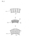
- Fig. 1 illustrates schematically a cross-section of an optical rotary encoder according to an example embodiment of the present invention.
- the rotary encoder is able to generate positional information with respect to the movement of two rotating objects. It may be used, for example, in applications together with machine tools and motors.
- the optical encoder of this example embodiment includes a code disc 10 with an incremental rotary scale 11.
- the rotary scale 11 consists of a track with alternatively arranged opaque and transparent areas of rectangular shape along the measurement direction.
- Rotary scale 11 is arranged circumferentially and symmetrically around the axis of rotation on the code disc 10 and has a defined radius R1 as illustrated in Fig. 1 .
- Code disc 10 is manufactured of glass or plastics, whereas the opaque areas of the rotary scale 11 are made of chrome deposited on the substrate material.
- the code disc 10 is mounted on a shaft 30 which may be connected with the rotor of a brushless motor for example.
- the rotary encoder has a scanning unit 20 which includes a light source 21, a collimating lens 22 and a detector array 23.
- the rotary scale 11 is arranged between the light source 21 and the collimating lens 22 on one side and the detector array 23 on the other side.
- the emitted light of the light source 21 is collimated by lens 22 and transmitted through the rotary scale 11 on the code disc 10.
- the detector array 23 arranged in the detection plane receives the transmitted light which is modulated by the rotary scale 11 if it rotates around axis 31.
- a fringe pattern which is cyclically modulated in dependence of the code disc rotation is generated in the detection plane.
- the modulated fringe pattern may be scanned in a conventional manner by the detector array 23 to generate scanning signals S0, S90, S180, S270. These position-dependent, intensity modulated signals S0, S90, S180, S270 are further processed in a downstream arranged control unit.
- an index mark 12 is arranged in a further track on the code disc 10 at a defined position adjacent to the incremental rotary scale 11.
- the index mark 12 is used to generate a so-called reference signal at a well-defined absolute position along the measuring path so that the incremental measurement via scanning of the incremental rotary scale may be referenced with respect to a certain absolute position. It is also possible in alternative example embodiments that a plurality of index marks are arranged on the code disc, etc.
- the rotary scale 11 of this transmitted light encoder example includes an incremental pattern of alternating transparent and non-transparent areas on the code disc 10 arranged along the measurement direction
- the rotary scale may also be composed of alternating areas of high reflectivity and low reflectivity in an incident light encoder example embodiment.
- the encoder structure is illustrated only schematically in Fig. 1 because details of its mechanical construction are believed to be understood to those of ordinary skill in the art.
- the detector array 23 of scanning unit 20 of the rotary encoder illustrated in Fig. 1 may be used together with scales having different radii. It may not be necessary to design a completely new detector array hardware for scanning, e.g., different rotary scales.
- the identical detector array hardware may be used in different configuration states to scan at least two scales with different radii. An enormous reduction of otherwise necessary design work may result based on this flexibility.
- FIG. 2 illustrates an example embodiment of a photodiode detector array 123 together with partial views of two rotary scales 111.1, 111.2 having different radii R1, R2 (R1 > R2).
- Rotary scales 111.1 and 111.2 are formed of a track with alternately arranged areas of different optical properties, e.g., transparent and opaque areas in the case of a transmitted light encoder example embodiment.
- Detector array 123 and rotary scales 111.1 or 111.2 are movable with respect to each other along measurement direction x.
- the identical photodiode detector array 123 may be used to scan a first incremental rotary scale 111.1 having a first radius R1 as well as to scan a second incremental rotary scale 111.2 having a second radius R2. Both radii R1, R2 differ as schematically indicated in Fig. 2 .
- photodetector array 123 includes a plurality of rectangular shaped photodiodes 124 acting as photodectecting devices in the detection plane.
- the photodiodes 124 are arranged adjacent to each other along the measurement direction x on at least a partial circle segment.
- Measurement direction x corresponds to the direction of rotational movement of the rotary scales 111.1, 111.2.
- each photodiode 124 of the photodetector array 123 provides a periodic scanning signal S0, S90, S180, S270 having a defined phase relationship with respect to the scanned rotary scale 111.1, 111.2.
- Those photodiodes 124 which generate scanning signals S0, S90, S180, S270 with the identical phase relationship are electrically connected with each other and form a group of photodiodes providing scanning signals of a defined phase.
- the scanning signals S0, S90, S180, S270 generated by the photodiodes 124 are sine-shaped.
- phase-different scanning signals S0, S90, S180, S270 is generated by a certain number of single photodiodes 124 which are suitably connected or switched together via switching elements.
- Four quadrature scanning signals S0, S90, S180, S270 may be generated which are phase shifted with respect to each other by a defined phase amount.
- Scanning signals S90, S180, S270 are phase shifted with respect to signal S0 by 90°, 180° and 270°.
- Quadrature scanning signals S0, S90, S180, S270 may be processed by a downstream arranged evaluation unit in a conventional manner so that two incremental output signals A, B are available, e.g., for control purposes, the output signals A, B being phase shifted with respect to each other by 90°.
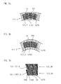
- Figs. 3a and 3b schematically illustrate the application of the detector array of Fig. 2 to the different rotary scales 111.1, 111.2 having radii R1 and R2. Due to the different switching states or configuration states the detector array is designated with different numerals 123_1, 123_2 in Figs. 3a and 3b .
- different hatchings of the photodiodes in the detector array 123_1, 123_2 indicate the different phase relationships of the photodiodes in the detector array.
- four different kinds of hatchings are shown to illustrate that there are four phase-different scanning signals S0, S90, S180 and S270 generated by scanning the corresponding rotary scale 111.1 or 111.2.
- the detector array used in this example includes two photodiode tracks being arranged adjacent and concentrically with respect to each other.
- Each of the photodiode tracks includes a partial photodiode array with photodiodes of rectangular (or more precisely trapezoidal) shape extending in radial direction.
- the partial photodiode arrays include physically separated photodiodes in both tracks which are suitably connected with each other. It is possible to arrange also more than two tracks in the detector array in this manner.
- Provision of two or more concentrically arranged photodiode tracks may reduce the generation of incorrect signal phase relationships of the signals produced by the outer photodiodes in the detector array.
- Fig. 3c is an enlarged view of the left outer area of the detector array configuration 111.2 which is suitable to operate at radius R2 and which is designed according to this principle.
- photodiodes providing different signal phases are marked by different hatchings.
- Fig. 3c it is illustrated, e.g., the manner in which photodiode 124(180)_A in the inner partial photodiode array 123_2A is assigned the phase relationship 180° whereas the radially adjacent photodiode 124(0)_B in the outer partial photodiode array 123_2B is assigned the phase relationship 0°, etc.
- the photodiodes in the detector arrays which provide signals of identical phase relationship are electrically connected together.
- the detector array includes a plurality of switching elements.
- the switching elements are used to combine the single photodiodes for each scanned scale radius in a well defined manner so that it may be ensured that output signals S0, S90, S180, S270 having the desired phase relationships are generated in at least two cases.
- the manner in which the photodiodes may be combined in both cases differs.
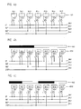
- Fig. 4a is a schematic partial view of a detector array 123 as described together with Fig. 2 as well as a plurality of switching elements 125.1 to 125.7 and four signal lines 126.1 to 126.4 for the four different scanning signals S0, S90, S180, S270 differing with respect to their phase relationship to the scanned scale structure.
- the schematic representations in Figs. 4a to 4c illustrate only one of the two partial photodiode arrays from Figs. 3a, 3b .
- Numerals 124.1 to 124.7 designate the seven shown photodiodes of the detector array 123 which include a typical application of 120 single photodiodes. Each photodiode 124.1 to 124.7 is connected with a switching element 125.1 to 125.7.
- the switching elements 125.1 to 125.7 include two single switches 1, 2 which allow to connect the respective photodiode 124.1 to 124.7 with at least one of the four signal lines 126.1 to 126.4. Either switch 1 or switch 2 of the different switching elements 125.1 to 125.7 has to be activated if a scale with radius R1 or radius R2 should be scanned with the photodiode array. If more (e.g., N) different radii are scanned, more switches (e.g., N) may be necessary per switching element. Switching elements 125.1 to 125.7 and their switches 1, 2 may be activated in a defined manner by suitable control lines. The choice of the correct connection between a single photodiode 124.1 to 124.7 and the appropriate signal line 126.1 to 126.4 depends on the scale radii which may be scanned with the detector array 123.
- FIGs. 4b and 4c illustrate two different manners in which the photodiodes 124.1 to 124.7 of the detector array 123 illustrated in Fig. 4a are connected with the signal lines 126.1 to 126.4 to generate the four phase-shifted scanning signals S0 to S270 at different scale radii R1, R2.
- Two differing configurations of the detector array 123_1, 123_2 result in these two exemplary cases.
- a part of the scanned scale structures 111.1 111.2 having transparent and opaque areas with different radii is also illustrated in Figs. 4b and 4c .
- the part of the detector array 123_1 as illustrated in Fig. 4b may be suitable to scan a first rotary scale having a first radius R1
- the part of the detector array 123_2 as illustrated in Fig. 4c may be suitable to scan a second rotary scale having a second radius R2.
- the different photodiodes 124.1 to 124.7 have to be assigned at least to one of the four different signal phases 0°, 90°, 180°, 270° or signal lines 126.1 to 126.4 respectively.
- Figs. 4b and 4c in both cases result different distributions of the phase different photodiodes 124.1 to 124.7 because of the different chosen switching states.
- signal phases 0°, 90°, 90°, 180°, 270°, 0°, 0° are assigned to the photodiodes 124.1 to 124.7 of the detector array optimized for scanning the radius R1.
- signal phases 0°, 90°, 180°, 270°, 0°, 90°, 180° are assigned to the photodiodes 124.1 to 124.7 of the detector array optimized for scanning the radius R2.
- Both array configurations may offer a suitable signal quality for generating the required four phase-different scanning signals S0 to S270.
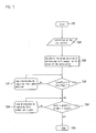
- a method is described in which a given, suitable photodiode detector array for generating four quadrature incremental scanning signals may be optimized via suitable activation of the switching elements for one of at least two different scale radii in an optical rotary encoder.
- step S20 After starting the optimization procedure in step S10, the disc pattern which may be used in the desired application as rotary scale has to be defined in step S20. This means that the radius R of the rotary scale on the code disc may have to be chosen. Furthermore, step S20 requires choosing the pitch P of the incremental rotary scale.
- the pitch P of the scanned incremental scale is defined as combined length of adjacently arranged opaque and transparent parts of the scale as illustrated in Fig. 6 .
- Step S20 also requires defining the radial extension of the scale structure as well as defining the concrete geometry of the opaque and transparent parts of the scale.
- next steps S30 to S70 are related to the optimization of the photodiode detector array and the appropriate positioning or respectively interconnecting of the photodiodes and/or parts thereof with the different switching elements.
- step S30 the phase position of the different photodiodes is determined in the detector array with respect to the rotary scale structure.
- Fig. 6 illustrates a part of the scale structure 211 together with a part of the photodiode detector array 223 with several photodiodes D1 to D10 of the detector array 223.
- the phase relationships between the photodiodes D1 to D10 and the scale 211 are schematically illustrated in Fig. 6 .
- Step S30 first requires to define the center phase values of the photodiodes which are used to generate the signals S0, S90, S180, S270 relative to the scale structure.
- the center phase value of photodiode D1 generating the signal S0 is chosen to be assigned 40°
- the center phase value of photodiode D2 generating the signal S90 is chosen to be assigned 115°
- the center phase value of photodiode D3 generating the signal S180 is chosen to be assigned 180°
- the center phase value of photodiode D4 generating the signal S270 is chosen to be assigned 250°.
- step S50 the optimization method continues with step S50. Otherwise, the photodiodes are swapped regarding their phase position according to step S45 as long as equations (1a) and (1b) are at least approximately fulfilled. Swapping of photodiodes in the course of the optimization process may be achieved by activating different switching configurations.
- step S50 a further check is made with respect to the number of photodiodes per signal phase.
- it is tried to equalize the number of photodiodes generating signals with different phase relationships.
- This requirement may be expressed by the following relationship (2): N 0 ⁇ ° ⁇ N 90 ⁇ ° ⁇ N 180 ⁇ ° ⁇ N 270 ⁇ ° in which N(0°) represents the number of photodiodes generating 0° signals, N(90°) represents the number of photodiodes generating 90° signals, N(180°) represents the number of photodiodes generating 180° signals, and N(270°) represents the number of photodiodes generating 270° signals.
- the number of photodiodes for different signal phases is chosen according to this requirement, it may be ensured that all incremental scanning signals generated by the photodetector array have approximately identical signal amplitudes and signal offsets. This may be important in connection with further processing these signals, e.g., in subsequent interpolation electronics.
- step S70 If relationship (2) is also fulfilled, the optimization procedure is finished at step S70. Otherwise, the different photodiodes are swapped according to step S60 as long as this condition is fulfilled at least approximately.
- This optimization procedure may be executed for each of at least two different scale radii for the detector array. As result of this procedure, a suitable configuration of the detector array is available for the different scale radii.
- the detector array optimized by a procedure as described above to at least two different finite radius values.
- the problem of a certain phase mismatch at the outer areas of the array may be solved by splitting the array and providing at least two photodiode tracks in radial direction as already mentioned above.
- Another approach to deal with this is illustrated in Fig. 7 .
- Fig. 7 illustrates a part of a rotary scale 311 having a radius R1 which may be scanned with detector array 322.
- the array may be arranged in the scanning unit radially displaced by a certain displacement amount ⁇ R1.
- ⁇ R1 describes the detector array displacement amount calculated from a relative position of the detector array 322 and the rotary scale 311 where there is complete overlap.
- the adapted detector array 322 may have to be arranged displaced radially by a displacement amount ⁇ R2 if the second rotary scale having radius R2 is scanned.
- Fig. 8 schematically illustrates an example embodiment of a photodiode detector array together with two scale index marks for different rotary scale radii similar to the situation illustrated in Fig. 2 which describes the scanning of two incremental rotary scales having different radii.
- the tracks with the incremental rotary scales are omitted in Fig. 8 .
- the detector array 223 illustrated in Fig. 8 may be used to scan a first index mark 211.1 as well as a second index mark 211.2.
- First and second index marks 211.1, 211.2 may be arranged on code discs with different radii adjacent to the incremental rotary scale track in a conventional manner.
- the first index mark 211.1 may be used together with rotary scale 111.1 in Fig. 2
- the second index mark 211.2 may be used together with rotary scale 111.2 in Fig. 2 .
- both index marks are adapted and optimized for a certain radius R1 or R2.
- the index marks 211.1, 211.2 include irregular distributions of areas on the code disc having different optical properties. In a transmitted light encoder as discussed above, the areas of the index mark are opaque and transparent.
- the detector array 223 which is movable along the measurement direction x versus the index marks 211.1 or 211.2 may be used to scan index marks being adapted to different radii to generate one or more defined reference signals. This is possible due to the flexibility in switching different photodiodes of the array together with suitable switching elements and adapting it to a certain defined index mark geometry.
- Figs. 9a and 9b The appropriate switching states of the detector array 223_1, 223_2 together with the different index marks at different radii are schematically illustrated in Figs. 9a and 9b . As illustrated, the manner in which the photodiodes are switched together is different for both radii and depends on the chosen index mark structures.
- the foregoing may also be used in connection with scanning index marks at different radii.
- No additional design work with regard to the detector array hardware may be necessary if such an array is used together with index marks being optimized for different radii.
Landscapes
- Physics & Mathematics (AREA)
- General Physics & Mathematics (AREA)
- Optical Transform (AREA)
- Transmission And Conversion Of Sensor Element Output (AREA)
Claims (14)
- Ein Detektor-Array (23; 123; 223) für optische Positionsmesseinrichtungen zur Erzeugung von Positionsinformationen für einen Maßstab (11; 111.1, 111.2; 211; 311), der gegenüber dem Detektor-Array (23; 123; 223) beweglich ist, wobei das Detektor-Array (23; 123; 223) dazu ausgebildet ist, in Verbindung mit mindestens zwei Maßstäben (11; 111.1, 111.2; 211; 311) mit unterschiedlichen Radien (R1, R2) verwendet zu werden, wobei das Detektor-Array (23; 123; 223) umfasst:eine Vielzahl von Fotodioden (124), wobei jede Fotodiode (124) dazu ausgebildet ist, ein Positionssignal zu erzeugen, wenn sich das Detektor-Array (23; 123; 223) gegenüber dem Maßstab (11; 111.1, 111.2; 211; 311) bewegt; undeine Vielzahl von Schaltelementen (125.1 - 125.7), die dazu ausgebildet sind, selektiv jede Fotodiode (124) mit anderen Fotodioden (124) in definierter Art und Weise zu verbinden;wobei die Schaltelemente (125.1 - 125.7) derart ausgebildet sind, dass darüber die Fotodioden (124) eindeutig für mindestens zwei unterschiedliche Maßstabradien (R1, R2) kombinierbar sind, um Positionssignale zu erzeugen, und sich die Kombinationen der Fotodioden (124) für die mindestens zwei unterschiedlichen Maßstabradien (124) unterscheiden; und
wobei die Vielzahl von Fotodioden (124) in mindestens zwei Fotodioden-Spuren angeordnet sind und jede Spur ein partielles Fotodioden-Array mit Fotodioden (124) aufweist, die sich in radialer Richtung erstrecken und wobei die verschiedenen Fotodioden-Spuren konzentrisch zueinander angeordnet sind. - Das Detektor-Array (23; 123; 223) gemäß Anspruch 1, wobei die partiellen Fotodioden-Arrays in den Spuren physikalisch separierte Fotodioden (124) in den Spuren umfassen und die Spuren gegeneinander um einen bestimmten umfangsmäßigen Versatzbetrag versetzt angeordnet sind.
- Das Detektor-Array (23; 123; 223) gemäß Anspruch 1, wobei die verschiedenen Maßstabradien (R1, R2) einen ersten endlichen Radius und einen zweiten endlichen Radius umfassen und wobei der erste endliche Radius unterschiedlich vom zweiten endlichen Radius ist.
- Das Detektor-Array (23; 123; 223) gemäß Anspruch 1, wobei die verschiedenen Maßstabradien (R1, R2) einen ersten endlichen Radius und einen zweiten unendlichen Radius umfassen.
- Das Detektor-Array (23; 123; 223) gemäß Anspruch 1, wobei jede Fotodiode (124) dazu ausgebildet ist, ein Abtastsignal mit einer bestimmten Phasenbeziehung zum Maßstab (11; 111.1, 111.2; 211; 311) zu erzeugen, wenn das Detektor-Array sich gegenüber dem Maßstab (11; 111.1, 111.2; 211; 311) bewegt, so dass eine definierte Anzahl von phasenverschobenen Abtastsignalen (S0, S90, S180, S270) erzeugt wird, indem die Fotodioden (124) über die Schaltelemente (125.1 - 125.7) für jeden verschiedenen Maßstabradius (R1, R2) kombiniert werden.
- Das Detektor-Array (23; 123; 223) gemäß Anspruch 5, wobei Fotodioden (124) in unterschiedlichen Spuren angeordnet sind, um inkrementale Abtastsignale (S0, S90, S180, S270) mit identischen Phasenbeziehungen zu erzeugen und wobei die Schaltelemente (125.1 - 125.7) dazu ausgebildet sind, die Fotodioden (124) in verschiedenen Spuren zu verbinden.
- Das Detektor-Array (23; 123; 223) gemäß Anspruch 5, wobei eine Vielzahl von benachbarten Fotodioden (124) in jeder Spur angeordnet ist, um inkrementale Abtastsignale (S0, S90, S180, S270) mit identischen Phasenbeziehungen zu erzeugen und wobei die Schaltelemente (125.1 - 125.7) dazu ausgebildet sind, die Vielzahl von benachbarten Fotodioden (124) miteinander zu verbinden.
- Das Detektor-Array (23; 123; 223) gemäß Anspruch 5, wobei die zumindest zwei Fotodioden-Spuren zwei Spuren mit partiellen Fotodioden-Arrays umfassen und wobei jede Spur vier Gruppen von Fotodioden (124) umfasst, um vier inkrementale Abtastsignale (S0, S90, S180, S270) mit Phasenbeziehungen 0°, 90°, 180° und 270° zu erzeugen.
- Das Detektor-Array (23; 123; 223) gemäß Anspruch 8, wobei jede Gruppe von Fotodioden (124) die identische Anzahl von Fotodioden umfasst.
- Das Detektor-Array (23; 123; 223) gemäß Anspruch 5, wobei die partiellen Fotodioden-Arrays in den Spuren physikalisch separierte Fotodioden (124) in den Spuren umfassen und wobei über korrespondierende Schalterkonfigurationen den Fotodioden (124) unterschiedliche Phasenbeziehungen zugewiesen sind, die sich entlang einer gemeinsamen radialen Richtung erstrecken.
- Das Detektor-Array (23; 123; 223) gemäß Anspruch 5, wobei das Detektor-Array (23; 123; 223) in radialer Richtung gegenüber dem Maßstab (11; 111.1, 111.2; 211; 311) versetzt um einen radialen Versatzbetrag angeordnet ist, um definierte Phasenbeziehungen aller Ausgangssignale der Fotodioden über die komplette Array-Länge in Messrichtung (x) zu erzeugen.
- Ein Detektor-Array (223) gemäß Anspruch 1 zur Erzeugung von Positionsinformationen für eine rotierende Teilscheibe mit einem kreisringförmig angeordneten rotatorischen Maßstab (211) und mindestens einer Referenzmarke (211.1, 211.2), wobei das Detektor-Array (223) dazu ausgebildet ist, in Verbindung mit mindestens zwei unterschiedlichen rotatorischen Maßstäben (211) mit unterschiedlichen Radien (R1, R2) verwendet zu werden und wobei das Detektor-Array (223) umfasst:eine Vielzahl von Fotodioden, wobei jede Fotodiode dazu ausgebildet ist, ein Referenzsignal zu erzeugen, wenn das Detektor-Array (223) sich gegenüber dem rotatorischen Maßstab (211) bewegt; undeine Vielzahl von Schaltelementen, die dazu ausgebildet sind, jede Fotodiode selektiv mit anderen Fotodioden in definierter Art und Weise zu verbinden;wobei die Schaltelemente derart ausgebildet sind, dass Fotodioden eindeutig miteinander für die mindestens zwei verschiedenen Maßstabradien (R1, R2) kombinierbar sind, um mindestens ein definiertes Referenzsignal zu erzeugen und wobei sich die Kombinationen von Fotodioden bei den mindestens zwei unterschiedlichen Maßstabradien (R1, R2) unterscheiden.
- Das Detektor-Array (23; 123; 223) gemäß Anspruch 1, wobei jede Spur zwei Gruppen von Fotodioden (124) umfasst, die dazu ausgebildet sind, zwei Referenzabtastsignale zu erzeugen, welche um 180° phasenversetzt zueinander sind.
- Ein Drehgeber, umfassend eine rotierende Teilscheibe (10) und ein Fotodioden Detektor-Array (23; 123; 223) gemäß mindestens einem der Ansprüche 1 bis 13.
Applications Claiming Priority (1)
| Application Number | Priority Date | Filing Date | Title |
|---|---|---|---|
| US10/927,990 US7199354B2 (en) | 2004-08-26 | 2004-08-26 | Detector array for optical encoders |
Publications (3)
| Publication Number | Publication Date |
|---|---|
| EP1630528A2 EP1630528A2 (de) | 2006-03-01 |
| EP1630528A3 EP1630528A3 (de) | 2009-08-05 |
| EP1630528B1 true EP1630528B1 (de) | 2010-06-02 |
Family
ID=35478730
Family Applications (1)
| Application Number | Title | Priority Date | Filing Date |
|---|---|---|---|
| EP05015944A Active EP1630528B1 (de) | 2004-08-26 | 2005-07-22 | Detektormatrix für optische Codierer |
Country Status (6)
| Country | Link |
|---|---|
| US (1) | US7199354B2 (de) |
| EP (1) | EP1630528B1 (de) |
| JP (1) | JP5030404B2 (de) |
| CN (1) | CN100483075C (de) |
| AT (1) | ATE470132T1 (de) |
| DE (1) | DE602005021584D1 (de) |
Families Citing this family (15)
| Publication number | Priority date | Publication date | Assignee | Title |
|---|---|---|---|---|
| US20060274798A1 (en) * | 2005-04-19 | 2006-12-07 | Bookham Technology Plc | Electronic wavelength marker system and method |
| JP2007064755A (ja) * | 2005-08-30 | 2007-03-15 | Samutaku Kk | エンコーダの信号処理回路 |
| DE102007050253A1 (de) * | 2007-10-20 | 2009-04-23 | Dr. Johannes Heidenhain Gmbh | Detektorelement-Array für eine optische Positionsmesseinrichtung |
| US8493572B2 (en) | 2010-05-05 | 2013-07-23 | Mitutoyo Corporation | Optical encoder having contamination and defect resistant signal processing |
| JP2012053023A (ja) * | 2010-09-03 | 2012-03-15 | Olympus Corp | エンコーダ |
| JP5765968B2 (ja) * | 2011-02-28 | 2015-08-19 | キヤノン株式会社 | 光学式エンコーダ |
| DE102011075286A1 (de) * | 2011-05-05 | 2012-11-08 | Dr. Johannes Heidenhain Gmbh | Optische Positionsmesseinrichtung |
| CN103712643B (zh) * | 2013-12-26 | 2015-12-16 | 南京埃斯顿自动化股份有限公司 | 一种编码器验证机构 |
| US11061338B2 (en) * | 2014-04-17 | 2021-07-13 | Nikon Corporation | High-resolution position encoder with image sensor and encoded target pattern |
| US11262376B2 (en) * | 2016-06-02 | 2022-03-01 | Weifang Goertek Microelectronics Co., Ltd. | MEMS device and electronic apparatus |
| US10551223B2 (en) * | 2017-03-20 | 2020-02-04 | Tt Electronics Plc | Method and apparatus for configurable photodetector array patterning for optical encoders |
| CN107063432B (zh) * | 2017-04-07 | 2019-07-12 | 华南师范大学 | 一种同时测量超声波方向、声强及频率的光学方法及装置 |
| US11378422B2 (en) | 2018-11-05 | 2022-07-05 | Tt Electronics Plc | Method and apparatus for improved performance in encoder systems by configuring a detector array using a partition map and assigning weights to output currents of the detector array |
| TWI680648B (zh) * | 2018-12-26 | 2019-12-21 | 財團法人工業技術研究院 | 編碼盤、檢光器、光學絕對式旋轉編碼器及編碼值輸出、偵錯與除錯的方法 |
| DE102020118639B3 (de) * | 2020-07-15 | 2021-01-07 | Sick Stegmann Gmbh | Codeelemente einer Maßverkörperung einer Gebervorrichtung |
Family Cites Families (11)
| Publication number | Priority date | Publication date | Assignee | Title |
|---|---|---|---|---|
| US4259570A (en) * | 1978-11-27 | 1981-03-31 | Hewlett-Packard Company | Optical comparator |
| US4786891A (en) * | 1986-04-08 | 1988-11-22 | Yokogawa Electric Corporation | Absolute encoder for linear or angular position measurements |
| DE3737278A1 (de) * | 1986-11-04 | 1988-05-11 | Canon Kk | Verfahren und vorrichtung zum optischen erfassen der stellung eines objekts |
| JP2794798B2 (ja) * | 1989-06-30 | 1998-09-10 | 株式会社安川電機 | エンコーダ |
| US5438330A (en) * | 1991-10-28 | 1995-08-01 | Nikon Corporation | Absolute encoder |
| DE4439693C2 (de) | 1994-11-05 | 1997-04-24 | Hengstler Gmbh | Sensoreinheit für einen Drehgeber oder Lineargeber |
| US5698851A (en) * | 1996-04-03 | 1997-12-16 | Placa Ltd. | Device and method for precise angular measurement by mapping small rotations into large phase shifts |
| FR2757628B1 (fr) * | 1996-12-20 | 1999-02-26 | Eaton Controls | Procede et dispositif de mesure numerique de positions angulaires |
| US6727493B2 (en) * | 2001-11-06 | 2004-04-27 | Renco Incoders, Inc. | Multiple resolution photodiode sensor array for an optical encoder |
| JP2003240607A (ja) * | 2002-02-18 | 2003-08-27 | Canon Inc | エンコーダの電気分割回路 |
| JP2005017116A (ja) * | 2003-06-26 | 2005-01-20 | Sharp Corp | 光学式エンコーダ用受光素子 |
-
2004
- 2004-08-26 US US10/927,990 patent/US7199354B2/en not_active Expired - Fee Related
-
2005
- 2005-07-22 AT AT05015944T patent/ATE470132T1/de not_active IP Right Cessation
- 2005-07-22 EP EP05015944A patent/EP1630528B1/de active Active
- 2005-07-22 DE DE602005021584T patent/DE602005021584D1/de active Active
- 2005-08-25 JP JP2005243704A patent/JP5030404B2/ja not_active Expired - Fee Related
- 2005-08-26 CN CNB2005100994605A patent/CN100483075C/zh active Active
Also Published As
| Publication number | Publication date |
|---|---|
| US20060043272A1 (en) | 2006-03-02 |
| JP2006064702A (ja) | 2006-03-09 |
| ATE470132T1 (de) | 2010-06-15 |
| EP1630528A3 (de) | 2009-08-05 |
| US7199354B2 (en) | 2007-04-03 |
| CN1740753A (zh) | 2006-03-01 |
| JP5030404B2 (ja) | 2012-09-19 |
| DE602005021584D1 (de) | 2010-07-15 |
| EP1630528A2 (de) | 2006-03-01 |
| CN100483075C (zh) | 2009-04-29 |
Similar Documents
| Publication | Publication Date | Title |
|---|---|---|
| EP1630528B1 (de) | Detektormatrix für optische Codierer | |
| EP0100243B1 (de) | Stellungsgeber | |
| CA2517397C (en) | Methods and apparatuses for the exact determination of an angle of rotation | |
| JP4327735B2 (ja) | 光回転角度トランスミッタ及び回転角度トランスミッタのコード円板を走査する方法 | |
| JP5538870B2 (ja) | ロータリーエンコーダ | |
| EP1308700B1 (de) | Fotodiodensensorarray mit Mehrfachauflösung für eine optische Kodiervorrichtung | |
| EP0801724B2 (de) | Optoelektronischer drehkodierer | |
| EP1010967B1 (de) | Kodierer zur Lieferung von inkrementalen und absoluten Positionswerten | |
| US8169619B2 (en) | Detector element matrix for an optical position measuring instrument | |
| JPS6331722B2 (de) | ||
| EP0518620B1 (de) | Kodierer der absoluten Position | |
| JP2007071732A (ja) | 光学式絶対値エンコーダ | |
| US6759647B2 (en) | Projection encoder | |
| EP2045579A2 (de) | Lichtdiodenarray für einen optischen Kodierer und optischer Kodierer | |
| JP4900140B2 (ja) | 光学式エンコーダ | |
| CN110132327B (zh) | 一种光电编码器 | |
| WO2022230665A1 (ja) | エンコーダ | |
| CN113518897B (zh) | 光学式旋转编码器、伺服马达以及致动器 |
Legal Events
| Date | Code | Title | Description |
|---|---|---|---|
| PUAI | Public reference made under article 153(3) epc to a published international application that has entered the european phase |
Free format text: ORIGINAL CODE: 0009012 |
|
| AK | Designated contracting states |
Kind code of ref document: A2 Designated state(s): AT BE BG CH CY CZ DE DK EE ES FI FR GB GR HU IE IS IT LI LT LU LV MC NL PL PT RO SE SI SK TR |
|
| AX | Request for extension of the european patent |
Extension state: AL BA HR MK YU |
|
| 17P | Request for examination filed |
Effective date: 20090216 |
|
| PUAL | Search report despatched |
Free format text: ORIGINAL CODE: 0009013 |
|
| AK | Designated contracting states |
Kind code of ref document: A3 Designated state(s): AT BE BG CH CY CZ DE DK EE ES FI FR GB GR HU IE IS IT LI LT LU LV MC NL PL PT RO SE SI SK TR |
|
| AX | Request for extension of the european patent |
Extension state: AL BA HR MK YU |
|
| 17Q | First examination report despatched |
Effective date: 20090922 |
|
| GRAP | Despatch of communication of intention to grant a patent |
Free format text: ORIGINAL CODE: EPIDOSNIGR1 |
|
| RIC1 | Information provided on ipc code assigned before grant |
Ipc: G01D 5/347 20060101AFI20100104BHEP |
|
| GRAS | Grant fee paid |
Free format text: ORIGINAL CODE: EPIDOSNIGR3 |
|
| AKX | Designation fees paid |
Designated state(s): AT BE BG CH CY CZ DE DK EE ES FI FR GB GR HU IE IS IT LI LT LU LV MC NL PL PT RO SE SI SK TR |
|
| GRAA | (expected) grant |
Free format text: ORIGINAL CODE: 0009210 |
|
| AK | Designated contracting states |
Kind code of ref document: B1 Designated state(s): AT BE BG CH CY CZ DE DK EE ES FI FR GB GR HU IE IS IT LI LT LU LV MC NL PL PT RO SE SI SK TR |
|
| REG | Reference to a national code |
Ref country code: GB Ref legal event code: FG4D |
|
| REG | Reference to a national code |
Ref country code: CH Ref legal event code: NV Representative=s name: ICB INGENIEURS CONSEILS EN BREVETS SA Ref country code: CH Ref legal event code: EP |
|
| REG | Reference to a national code |
Ref country code: IE Ref legal event code: FG4D |
|
| REF | Corresponds to: |
Ref document number: 602005021584 Country of ref document: DE Date of ref document: 20100715 Kind code of ref document: P |
|
| REG | Reference to a national code |
Ref country code: NL Ref legal event code: VDEP Effective date: 20100602 |
|
| PG25 | Lapsed in a contracting state [announced via postgrant information from national office to epo] |
Ref country code: LT Free format text: LAPSE BECAUSE OF FAILURE TO SUBMIT A TRANSLATION OF THE DESCRIPTION OR TO PAY THE FEE WITHIN THE PRESCRIBED TIME-LIMIT Effective date: 20100602 Ref country code: SE Free format text: LAPSE BECAUSE OF FAILURE TO SUBMIT A TRANSLATION OF THE DESCRIPTION OR TO PAY THE FEE WITHIN THE PRESCRIBED TIME-LIMIT Effective date: 20100602 |
|
| LTIE | Lt: invalidation of european patent or patent extension |
Effective date: 20100602 |
|
| PG25 | Lapsed in a contracting state [announced via postgrant information from national office to epo] |
Ref country code: FI Free format text: LAPSE BECAUSE OF FAILURE TO SUBMIT A TRANSLATION OF THE DESCRIPTION OR TO PAY THE FEE WITHIN THE PRESCRIBED TIME-LIMIT Effective date: 20100602 Ref country code: AT Free format text: LAPSE BECAUSE OF FAILURE TO SUBMIT A TRANSLATION OF THE DESCRIPTION OR TO PAY THE FEE WITHIN THE PRESCRIBED TIME-LIMIT Effective date: 20100602 Ref country code: SI Free format text: LAPSE BECAUSE OF FAILURE TO SUBMIT A TRANSLATION OF THE DESCRIPTION OR TO PAY THE FEE WITHIN THE PRESCRIBED TIME-LIMIT Effective date: 20100602 Ref country code: LV Free format text: LAPSE BECAUSE OF FAILURE TO SUBMIT A TRANSLATION OF THE DESCRIPTION OR TO PAY THE FEE WITHIN THE PRESCRIBED TIME-LIMIT Effective date: 20100602 |
|
| PG25 | Lapsed in a contracting state [announced via postgrant information from national office to epo] |
Ref country code: CY Free format text: LAPSE BECAUSE OF FAILURE TO SUBMIT A TRANSLATION OF THE DESCRIPTION OR TO PAY THE FEE WITHIN THE PRESCRIBED TIME-LIMIT Effective date: 20100602 Ref country code: GR Free format text: LAPSE BECAUSE OF FAILURE TO SUBMIT A TRANSLATION OF THE DESCRIPTION OR TO PAY THE FEE WITHIN THE PRESCRIBED TIME-LIMIT Effective date: 20100903 Ref country code: PL Free format text: LAPSE BECAUSE OF FAILURE TO SUBMIT A TRANSLATION OF THE DESCRIPTION OR TO PAY THE FEE WITHIN THE PRESCRIBED TIME-LIMIT Effective date: 20100602 |
|
| PG25 | Lapsed in a contracting state [announced via postgrant information from national office to epo] |
Ref country code: EE Free format text: LAPSE BECAUSE OF FAILURE TO SUBMIT A TRANSLATION OF THE DESCRIPTION OR TO PAY THE FEE WITHIN THE PRESCRIBED TIME-LIMIT Effective date: 20100602 Ref country code: NL Free format text: LAPSE BECAUSE OF FAILURE TO SUBMIT A TRANSLATION OF THE DESCRIPTION OR TO PAY THE FEE WITHIN THE PRESCRIBED TIME-LIMIT Effective date: 20100602 |
|
| PG25 | Lapsed in a contracting state [announced via postgrant information from national office to epo] |
Ref country code: SK Free format text: LAPSE BECAUSE OF FAILURE TO SUBMIT A TRANSLATION OF THE DESCRIPTION OR TO PAY THE FEE WITHIN THE PRESCRIBED TIME-LIMIT Effective date: 20100602 Ref country code: RO Free format text: LAPSE BECAUSE OF FAILURE TO SUBMIT A TRANSLATION OF THE DESCRIPTION OR TO PAY THE FEE WITHIN THE PRESCRIBED TIME-LIMIT Effective date: 20100602 Ref country code: CZ Free format text: LAPSE BECAUSE OF FAILURE TO SUBMIT A TRANSLATION OF THE DESCRIPTION OR TO PAY THE FEE WITHIN THE PRESCRIBED TIME-LIMIT Effective date: 20100602 Ref country code: IS Free format text: LAPSE BECAUSE OF FAILURE TO SUBMIT A TRANSLATION OF THE DESCRIPTION OR TO PAY THE FEE WITHIN THE PRESCRIBED TIME-LIMIT Effective date: 20101002 Ref country code: MC Free format text: LAPSE BECAUSE OF NON-PAYMENT OF DUE FEES Effective date: 20100731 Ref country code: PT Free format text: LAPSE BECAUSE OF FAILURE TO SUBMIT A TRANSLATION OF THE DESCRIPTION OR TO PAY THE FEE WITHIN THE PRESCRIBED TIME-LIMIT Effective date: 20101004 Ref country code: BE Free format text: LAPSE BECAUSE OF FAILURE TO SUBMIT A TRANSLATION OF THE DESCRIPTION OR TO PAY THE FEE WITHIN THE PRESCRIBED TIME-LIMIT Effective date: 20100602 |
|
| PG25 | Lapsed in a contracting state [announced via postgrant information from national office to epo] |
Ref country code: IT Free format text: LAPSE BECAUSE OF FAILURE TO SUBMIT A TRANSLATION OF THE DESCRIPTION OR TO PAY THE FEE WITHIN THE PRESCRIBED TIME-LIMIT Effective date: 20100602 |
|
| PLBE | No opposition filed within time limit |
Free format text: ORIGINAL CODE: 0009261 |
|
| STAA | Information on the status of an ep patent application or granted ep patent |
Free format text: STATUS: NO OPPOSITION FILED WITHIN TIME LIMIT |
|
| REG | Reference to a national code |
Ref country code: FR Ref legal event code: ST Effective date: 20110331 |
|
| PG25 | Lapsed in a contracting state [announced via postgrant information from national office to epo] |
Ref country code: DK Free format text: LAPSE BECAUSE OF FAILURE TO SUBMIT A TRANSLATION OF THE DESCRIPTION OR TO PAY THE FEE WITHIN THE PRESCRIBED TIME-LIMIT Effective date: 20100602 |
|
| 26N | No opposition filed |
Effective date: 20110303 |
|
| GBPC | Gb: european patent ceased through non-payment of renewal fee |
Effective date: 20100902 |
|
| PG25 | Lapsed in a contracting state [announced via postgrant information from national office to epo] |
Ref country code: FR Free format text: LAPSE BECAUSE OF NON-PAYMENT OF DUE FEES Effective date: 20100802 |
|
| REG | Reference to a national code |
Ref country code: DE Ref legal event code: R097 Ref document number: 602005021584 Country of ref document: DE Effective date: 20110302 |
|
| PG25 | Lapsed in a contracting state [announced via postgrant information from national office to epo] |
Ref country code: IE Free format text: LAPSE BECAUSE OF NON-PAYMENT OF DUE FEES Effective date: 20100722 |
|
| PG25 | Lapsed in a contracting state [announced via postgrant information from national office to epo] |
Ref country code: GB Free format text: LAPSE BECAUSE OF NON-PAYMENT OF DUE FEES Effective date: 20100902 |
|
| PG25 | Lapsed in a contracting state [announced via postgrant information from national office to epo] |
Ref country code: HU Free format text: LAPSE BECAUSE OF FAILURE TO SUBMIT A TRANSLATION OF THE DESCRIPTION OR TO PAY THE FEE WITHIN THE PRESCRIBED TIME-LIMIT Effective date: 20101203 Ref country code: BG Free format text: LAPSE BECAUSE OF FAILURE TO SUBMIT A TRANSLATION OF THE DESCRIPTION OR TO PAY THE FEE WITHIN THE PRESCRIBED TIME-LIMIT Effective date: 20100602 Ref country code: LU Free format text: LAPSE BECAUSE OF NON-PAYMENT OF DUE FEES Effective date: 20100722 |
|
| PG25 | Lapsed in a contracting state [announced via postgrant information from national office to epo] |
Ref country code: TR Free format text: LAPSE BECAUSE OF FAILURE TO SUBMIT A TRANSLATION OF THE DESCRIPTION OR TO PAY THE FEE WITHIN THE PRESCRIBED TIME-LIMIT Effective date: 20100602 |
|
| PG25 | Lapsed in a contracting state [announced via postgrant information from national office to epo] |
Ref country code: BG Free format text: LAPSE BECAUSE OF FAILURE TO SUBMIT A TRANSLATION OF THE DESCRIPTION OR TO PAY THE FEE WITHIN THE PRESCRIBED TIME-LIMIT Effective date: 20100902 |
|
| PG25 | Lapsed in a contracting state [announced via postgrant information from national office to epo] |
Ref country code: ES Free format text: LAPSE BECAUSE OF FAILURE TO SUBMIT A TRANSLATION OF THE DESCRIPTION OR TO PAY THE FEE WITHIN THE PRESCRIBED TIME-LIMIT Effective date: 20100913 |
|
| REG | Reference to a national code |
Ref country code: CH Ref legal event code: PL |
|
| PG25 | Lapsed in a contracting state [announced via postgrant information from national office to epo] |
Ref country code: CH Free format text: LAPSE BECAUSE OF NON-PAYMENT OF DUE FEES Effective date: 20180731 Ref country code: LI Free format text: LAPSE BECAUSE OF NON-PAYMENT OF DUE FEES Effective date: 20180731 |
|
| PGFP | Annual fee paid to national office [announced via postgrant information from national office to epo] |
Ref country code: DE Payment date: 20230719 Year of fee payment: 19 |